Good day to all! In the last article, I talked about the calculation of AC chokes, a feature of which is the absence of DC bias current. Such chokes are widely used in voltage converters. Another electromagnetic device used in converter technology is a transformer, which is several chokes connected by a common magnetic circuit.
To assemble a radio-electronic device, you can pre-make a DIY KIT kit using the link.
In addition to converter technology, transformers are widely used in pulse, amplification and power electronics. Therefore, depending on their purpose and design features, transformers are divided into several categories and types.
In this article I will talk about the types of transformers and the features of their designs.
Characteristics and principle of operation
The principle of operation of the MF is to increase the magnetic field directed to the secondary winding of the electrical device. The characterizing values of MF directly depend on the composition of the alloy used for the manufacture of cores. Ferromagnets are considered the most effective amplifiers.
Magnetic induction lines
Read also: What seas and oceans wash Eurasia?
In order for the magnetic flux strength in the core to constantly increase, it is necessary to increase the current strength and the number of turns in the coil.
You should understand! The magnitude of the magnetic field is limited by the characteristics of the material from which the core is made.
To clearly express the characteristics of the magnetic circuit, they are displayed graphically on coordinate axes. The change in values looks like a closed curved line called a hysteresis loop.
Magnetic field amplifier
The electromagnetic field is inextricably linked with current. Its properties are used in all electrical machines, electronics and automation devices. The purpose of magnetic cores is to transmit and amplify the magnetic field.
A magnetic field amplifier is a core surrounded by turns of coils (windings). Depending on the type of material used, certain characteristics of the MP are achieved.
There are two types of amplifiers based on their operating principle:
- amplistates – UMPs of static design;
- Transducers are a device with moving elements.
Operating modes
The characteristics of transformers are determined by operating conditions, where the load resistance plays a key role. The following modes are used as a basis:
- Idle move. The outputs of the secondary circuit are in an open state, the load resistance is equal to infinity. Measuring the magnetizing current flowing in the primary winding makes it possible to calculate the efficiency of the transformer. Using this mode, the transformation ratio is calculated, as well as losses in the core;
- Under load (working). The secondary circuit is loaded with a certain resistance. The parameters of the current flowing through it are directly related to the ratio of the turns of the coils.
- Short circuit. The ends of the secondary winding are short-circuited, the load resistance is zero. The mode informs about losses that are caused by heating of the windings, which in professional language is referred to as “copper losses”.
Short circuit mode
Information about the behavior of the transformer in various modes is obtained experimentally using equivalent circuits.
How to reduce losses
The magnitude of magnetization reversal losses depends on several factors:
- properties of the substance from which the core is made. Materials that are difficult to magnetize are also difficult to remagnetize. And the more energy is consumed, which is expressed in heating;
- magnetization reversal frequencies;
- the highest value of magnetic induction.
Losses are reduced through the use of special transformer steel. It requires less energy for magnetization reversal compared to other substances.
How are magnetic circuits arranged?
A magnetic circuit, in fact, is not as difficult to imagine as it might seem to a person who hears about them for the first time. Usually . Perhaps one of the simplest single-source examples to use is illustrated below:
Before continuing, let us agree that among electrical engineers the core is called a magnetic circuit . The part of the magnetic circuit on which there are no windings and which serves to close the magnetic circuit is called the “yoke”.
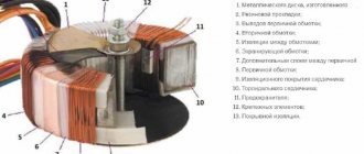
Let's start with the toroidal core. Such a toroidal core can serve as a form for a coil, no matter how strange it may sound. But what kind of coil? Well, the first thing that comes to mind is a wire that forms turns. Okay, but what is its purpose? Let's return to electrical circuits and remember that there are current / voltage sources, the so-called. So, in magnetic circuits
Let us now remember about ferromagnetic materials. Why them? The fact is that due to the high value of magnetic permeability, which indicates good magnetization of the ferromagnet, the magnetic field lines practically do not extend beyond the core, or do not extend at all. However, this will only be true when our core is closed or has small gaps . That is, ferromagnets have strongly pronounced magnetic properties, when, like paramagnets and diamagnets, they are much weaker, which can be observed in the following graph of the dependence of magnetization on the magnetic field strength:
Main types of cores
Transformers have different areas of application, technical characteristics, and dimensions. They also differ in the type of magnetic circuits. Structurally, the cores are divided into three main types: The rod core is designed in the shape of the letter P and consists of two rods connected by a yoke. If necessary, protect the windings from external influences using armored magnetic cores. The yoke is located on the outer part and completely covers the rod with the winding located inside.
Cores are also classified according to the method of assembling the plates:
- set of stamped plates. The advantages of magnetic cores made from sheets include the possibility of their manufacture from not very durable materials;
- wound metal tapes. Such cores utilize magnetic energy more fully, but at the same time have an increased level of losses. Toroidal winding of tapes is the most complex, but energetically the most favorable.
There are differences in the connection of the rods to the yoke. They are collected in two ways:
About power amplifiers
The energy entering inside is enhanced by 3-5 times. From the outside, the devices look like boxes made of metal or plastic. Inside there is an electrical circuit similar to an inverter. It is complemented by a transformer, which is most often asymmetrical. The main thing is to check the transformer and amplifier before starting work. The principle remains the same as before.
What is a transformer core: structure and types of magnetic circuits
A transformer is installed in electrical networks to convert alternating current voltage. The main parts of the device are the core and windings. Windings are coils that are wound of conductive metal around a core. For these purposes, copper or aluminum is most often used. Under load, voltage is applied to the primary winding. The current passes through the winding and causes a magnetic flux to appear in the core. As a result, voltage also arises in the second winding. And its value depends on the number of turns of wire on the primary and secondary windings.
Additional Tips
In any electrical over-unit circuits there are 5 main elements:
- Source of additional energy.
Usually this is inductance or a transformer with asymmetric operation. But you can also use other devices that create electric or electrostatic fields.
- Inverter.
Another name is the equivalent energy converter of electricity. This refers to particles and voltage, current.
- Energy storage.
A battery, capacitor and other similar devices perform this function without problems.
- A controller that controls the circuit itself and how energy moves through it.
- Loads.
Working with a base in the form of a specific circuit, a source of additional energy are the main parts of any design. The remaining parts can be called servicing. Due to them, not only energy distribution occurs, but also partial power return, compensating for resistance.
Design features
Magnetic cores are manufactured in butt and laminated versions. The designs differ in the way the cores are connected to the yokes (the part of the cores without windings).
Butt design
The MP parts are assembled separately. Windings are installed on vertical cores. Then they are fastened with a horizontal upper yoke using pins. After this, the lower yoke is mounted. This design is convenient in that by removing the studs and removing the horizontal section, you can always change the windings. The butt design is used in shunt current-limiting devices of reactors.
Laminated structures
The rods and yokes are made in the form of layered slabs. Each package consists of two or three layers of steel plates. Connections of parts are made by inserting elements into the gaps between the layers of the magnetic circuit. This method of installing MP parts is called laching. The complexity of forming the entire structure of the transformer causes the risk of poor-quality assembly of the device.
Stages of production of lamellar magnetic cores, features of assembly of lamellar magnetic cores
In their design and properties, lamellar (laminated) magnetic cores differ significantly from twisted tape and ring (toroidal) magnetic cores. The production of cores of this type is regulated by GOST 20249-80 and is carried out according to the following scheme:
- Cutting materials. Produced on slitting units equipped with circular knives. The material is cut into strips of the required sizes.
- Cutting plates. Parts are cut using guillotines and cross-cutting units (including punching holes in the plates).
- Assembly of magnetic circuits. It is produced using the technology of assembling butt or laminated magnetic cores.
- Quality control. Measuring the main characteristics of the resulting products and their compliance with the technical specifications
The procedure consists of a set of plates in a package and their fastening (pulling) together. The parts are connected in several ways:
- studs and bolts;
- crimping staples;
- metal holder.
An important assembly condition is the isolation of fasteners from the magnetic circuit. In some cases, the package is compressed. In this case, a change in magnetic permeability and electrical resistance occurs. The procedure is performed at a pressure of 2-5 MPa, the compression force is selected depending on the materials and design of the plates.
After compression, quality control must be carried out. With its help, it is possible to find out the resulting magnetic induction and permeability, as well as the no-load current of the plate magnetic circuit.
Compliance with a precise technological process allows us to obtain reliable and durable structures that can withstand heavy loads and are ready for use in almost any conditions.
It will be interesting➡ The best radios of 2022: selection criteria and rating
Conclusion
It is difficult to create super-unit transformers, but the result will be worth all the effort. The installations have an increased efficiency rate, regardless of which devices they are connected to.
You just need to competently develop a scheme and ensure that the indicators meet the needs of the owners. In this case, there are no problems with further operation, the characteristics are preserved for a long time.
Features of impulse loads
For devices carrying pulsed loads, special transformers are used. They are capable of converting voltage and current under pulsed loads and withstanding their destructive effects. The types of cores of pulse transformers do not differ in shape from other types of devices.
Most often, the magnetic core is made in the form of a ferrite torus. The windings are wound on it in a special way: in the primary coil they are laid counterclockwise, and in the secondary coil they are laid clockwise.
Such a transformer can be made independently; you just need to take into account the requirements for conservation of momentum.
Technical specifications
- Rated current – allowing the device to function for a long time without overheating;
- Rated voltage – the value should ensure normal operation of the transformer. It is this indicator that affects the quality of insulation between the windings, one of which is at high voltage and the other is grounded.
- Transformation coefficient; Formula for calculating the transformation ratio
Where:- U1 and U2 – voltage in the primary and secondary windings,
N1 and N2 – number of turns in the primary and secondary windings,
- I1 and I2 – current in the primary and secondary windings (usually the current in the secondary winding is 1A or 5A).
- The error in the value of the electric current is caused by magnetization;
- Rated load, which determines the normal operation of the device;
- Nominal limit factor - the maximum permissible value of the ratio of the primary value of the electric current to the nominal value;
- The maximum multiple of the secondary current is the ratio of the highest current of the secondary winding to its nominal value.
Values that CTs may have
When choosing a device, it is necessary to take into account the value of these and other characteristics.
Superconducting electromagnet
Superconductivity is considered the property of materials with resistance close to zero. Electromagnets with practically zero resistance have a super-powerful magnetic field. The force of magnetic influence can cause diamagnetic materials such as pieces of lead and organic objects to float in space.
As physicists have noticed, metals acquire the property of superconductivity at ultra-low temperatures. To obtain the superconductivity effect, the EM windings are placed in a Dewar flask with liquid helium, which is equipped with a valve to release the vapor of the substance. Superconducting magnets are used in medical equipment - MRI (magnetic resonance tomography) machines. Experimental hovercraft trains use superconducting magnets.
Superconducting magnet
Ferrite grades
Ferrites according to their composition are divided into two groups: manganese-zinc and nickel-zinc. Manganese-zinc ferrites are designated by the letters NM, respectively, nickel-zinc substances are marked by the letters - NN. The number before the letter designation of ferrite means the value of the initial magnetic permeability in units of µinit. This indicator is given with an adjustment to the nominal value. For example, ferrite grade 4000NM has a magnetic permeability with a deviation ranging from – 800 to + 500 µinit.
Magnetic cores are of exceptional importance in the formation of devices such as transformers and other electrical devices. The initial technical characteristics of the devices largely depend on their qualitative composition.
Why is a magnetic circuit needed?
To understand what a magnetic circuit is, we need to consider the structure of a simple transformer. Two induction coils are wound on cores combined into a single structure. They are the magnetic circuits (MC).
Hysteresis loop
The energized primary coil induces a magnetic field into the core, which induces magnetic flux into the secondary winding. As a result, the MF induces a current in the second coil, but with different characteristics.
Important! The cores are made of special transformer steel - ferrites. It is an alloy of iron with oxides of other metals.
Application of transformers
When transmitting electricity over long distances, quite large losses can occur due to heating of the wires. To avoid such a negative phenomenon, transformers are repeatedly used. Initially, the voltage at the power plant is increased accordingly with a significant decrease in current. After the energy passes through the power lines, before delivering the current to the consumer, the voltage is reduced to an acceptable level (220 V) using transformers.
Since three-phase current flows in power line networks, groups of 3 single-phase transformers connected in a star or triangular circuit are used to transform it. Three-phase transformers with a single magnetic core are also used. The equipment has high efficiency. Due to this, a large amount of heat is released. Therefore, powerful transformers are placed in containers filled with special oil.
Powerful power transformer
Various electrical appliances require power supply at a certain voltage level. To do this, transformers with the required characteristics are built into their housings. High-frequency pulse transformers are used to power modern radio engineering and electronic devices.
Transformers are the basis of control and measuring devices. The point of using such devices is to safely transmit the shape of the voltage pulses of the electrical circuit under study. For example, instrument transformers are used in diesel generator systems with medium power currents (up to 1 megawatt).
Matching transformers are used when connecting devices with low resistance to electronic stages with high input or output resistance values. An example would be connecting an audio amplifier to speakers that have very low impedance.
Additional Information. The amount of energy losses in a transformer directly depends on the quality of the electrical steel core. Minimal losses due to heating, hysteresis and eddy currents occur where the cores are assembled from a large number of sections.
Classification of transformers according to electrical parameters
Classification according to these features of transformers allows us to assess the ability to use a particular type of transformer in a particular case. In accordance with this, transformers are divided into the following groups according to electrical parameters:
1. By operating frequency . Since the frequency of the alternating voltage current depends on the materials used from which the core, windings and insulation are made. In accordance with this, the following types of transformers are distinguished:
— low frequency – operating frequency below 50 Hz;
— industrial frequency – operating frequency 50 Hz;
— high frequency – operating frequency 100 – 10000 Hz;
— ultrasonic frequency – operating frequency more than 10 kHz;
— high frequency – operating frequency over 100 kHz.
For pulse transformers, the pulse duration is more often used. Currently, powerful transformers are in most cases powered by industrial frequency networks, but in modern electronics, transformers designed for high and ultrasonic frequencies are overwhelmingly used. This allows the dimensions of the transformer to be reduced.
2. According to the current system . This feature of the transformer allows transformers to be divided into:
— single-phase;
- multiphase (for example, three-phase, six-phase, etc.).
3. According to the magnitude of electrical voltage . This parameter characterizes the voltage value for which the insulation of any winding or windings of the transformer is designed. According to this parameter, transformers are divided:
- low-voltage transformers in which the operating voltage of the winding (or windings) does not exceed 1000 - 1500 V;
- high-voltage transformers with operating winding voltages above 1000 - 1500 V.
Currently, in most consumer electronics, low-voltage transformers are used.
4. By the amount of power . This parameter is quite conditional and is primarily introduced for the convenience of describing a specific transformer:
- low power , having a power of about ten W;
- average power , having a power of hundreds of W;
- high power , having a power of several kW.
What is the magnetic core of a transformer and why is it needed?
The magnetic circuit or core of the transformer allows voltage to be converted more efficiently, while reducing losses. For the manufacture of cores, special ferromagnetic steel is used.
Types of transformer cores
According to their structure, cores are divided into:
- rod;
- armored;
- toroidal.
The rod core has the shape of the letter P. The windings are mounted on the rods, and the rods themselves are connected by a yoke. This design of the magnetic circuit makes it easy to inspect and repair the windings. Therefore, this type is typical for medium and powerful transformers.
W-shaped armor core The windings are located on the central rod. Armor transformers are more difficult to manufacture. And repairing the windings in them is not as easy as in rod ones.
The toroidal core has the shape of a ring with a rectangular cross-section. The windings are wound directly onto it. Therefore, this type of core is considered the most energy efficient.
a – rod core, b – armor core, c – toroidal core.
Connection diagrams for windings of three-phase transformers
In most cases, the windings of three-phase transformers are connected either in star (Y) or delta (Δ).
The choice of winding connection diagram depends on a number of reasons. For example, for networks with a voltage of 35 kV and more, it is more profitable to connect the transformer winding in a star and ground the zero point, since in this case the voltage of the transformer terminals and transmission line wires relative to the ground will always be √ 3 times less than linear, which leads to a reduction in the cost of insulation. Incandescent lighting lamps of lower voltage have greater luminous efficiency, and it is advantageous to build lighting networks at a higher voltage. Therefore, the secondary windings of transformers supplying lighting networks are usually connected in a star and the lighting lamps are switched on to phase voltage - between the linear and neutral conductors. In a number of cases, when the winding current is small, when connected in a star, the windings are cheaper, since the number of turns is reduced by √3 times, and the cross-section of the wires also increases by √3 times, as a result of which the labor intensity of manufacturing the winding and the cost of the winding wire are reduced . On the other hand, from the point of view of the influence of higher harmonics and the behavior of the transformer under asymmetrical loads, it is advisable to connect one of the transformer windings in a triangle.
| Figure 1. Zigzag connection of three-phase winding |
In some cases, a zigzag connection of windings is also used (Figure 1), when the winding phase is divided into two parts, which are located on different rods and connected in series. In this case, the second half of the winding is connected counter to the first (Figure 1, a), since in this case the electromotive force (emf) of the phase will be √3 times greater (Figure 1, b) than with consonant switching on (Figure 1, c). However, when the halves of the winding are turned on oppositely, its e. d.s. (√3 E1) will still be 2 / √3 = 1.15 times less than when both halves are located on one rod (2 E1). Therefore, the consumption of winding wire when connecting with a zigzag increases by 15%. As a result, a zigzag connection is used only in special cases when uneven phase loading with the presence of zero-sequence currents is possible.
Specifications
An important characteristic is transformation ratios. They show the dependence of the output voltage on the ratio of turns in the windings. The transformation coefficient is the basic parameter in the calculation.
Another important characteristic of a transformer is its efficiency. In some devices this figure is 0.9 – 0.98, which characterizes insignificant losses of magnetic stray fields. Power P depends on the cross-sectional area S of the magnetic circuit. Based on the value of S, when calculating the parameters of the transformer, the number of turns in the coils is determined: W = 50 / S.
In practice, power is selected based on the expected load, taking into account losses in the core. The power of the secondary winding is Pн = Un× Iн , and the power of the primary coil is Pс = Uс × Iс . Ideally, Pn = Pc (if we neglect losses in the core). Then k = Uс / Un = Iс / Iн , that is, the currents in each of the windings have an inversely proportional dependence on their voltages, and therefore on the number of turns.
Hysteresis loop
Hysteresis in Greek means delay. The graphical representation of the hysteresis loop reflects the degree of magnetization of a body located in an external magnetic field. Hysteresis is the dependence of magnetization vectors and magnetic field strength in any medium on the applied external MF. The state of the body at a given time is compared with its previous state. In this case, there is a lag in the body’s reaction to the influence of external MF. The physical effect is clearly manifested in ferromagnets: iron, cobalt, nickel and their alloys. The hysteresis loop provides an explanation for the existence of permanent magnets.
Hysteresis loop
Note! Magnetic hysteresis of a ferromagnet is the lag between changes in the degree of magnetization of a body and changes in the external magnetic field. That is, the loop shows the dependence of the degree of magnetization on the sample’s history
The magnetic permeability of a ferromagnet is a variable value; it is closely related to the induction of an external field. The magnetization curve of the core is a curved loop, at a certain degree of saturation of the ferromagnetic field. In the future, this value does not increase. If the external induction is reduced to zero, the ferromagnet will retain residual magnetization. When the direction of the external field changes, the ferromagnet is remagnetized in the opposite direction.
Principle of operation
The operating principle of current transformers is based on the law of electromagnetic induction. Voltage from the external network is supplied to the power primary winding with a certain number of turns and overcomes its total resistance. This leads to the appearance of a magnetic flux around the coil, captured by the magnetic circuit. This magnetic flux is located perpendicular to the direction of the current. Due to this, losses of electric current during the conversion process will be minimal.
When the turns of the secondary winding, located perpendicularly, intersect, the electromotive force is activated by the magnetic flux. Under the influence of the EMF, a current appears that is forced to overcome the total resistance of the coil and the output load. At the same time, a voltage drop is observed at the output of the secondary winding.
About bifilar winding as an additional element
Suppression of electromagnetic fields of inductance is the main purpose performed by such a device. An additional type of winding helps conserve current. Because of this, in the 1st and 3rd cycles of the cycle, a decrease in inductive reactance occurs.
At such moments, the continued influence of counter-emf forces due to the self-inductance of the coil is assumed.
As for the 3rd and 4th cycles, here the forces of self-induction make it possible to maintain this inside the coil. Then one of the parts of the bifilar coil must be turned off, otherwise the induction work of the second part and the winding, due to which the initial current was created, does not begin. A single transformer works in this case.
The power increases for the device, which acts as a source of additional energy. Maintaining the following conditions assumes constant excitation of current in the coil:
- Little power is wasted.
- Low EMF value.
- 1.3 cycles with a lot of current.
2nd and 4th cycles are accompanied by the connection of an additional EMF.