One of the main parameters of an asynchronous electric motor is slip. This is a variable value. It can change based on the modes in which the motor operates, the voltage, and the gross load.
In the article we will look at what this phenomenon is, how it is calculated, and on what conditions it depends.
What it is
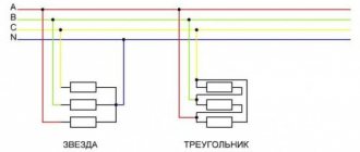
The operating principle of a three-phase asynchronous motor is quite simple. A supply voltage is supplied to the stator winding, which creates a magnetic flux; in each phase it will be shifted by 120 degrees. In this case, the summing magnetic flux will be rotating.
The rotor winding is a closed circuit, an EMF is induced in it and the resulting magnetic flux imparts rotation to the rotor in the direction of movement of the stator magnetic flux. The electromagnetic torque tries to equalize the speed of rotation of the magnetic fields of the stator and rotor.
The value that determines the difference in the rotation speeds of the magnetic fields of the rotor and stator is called slip . Since the rotor of an asynchronous motor always rotates slower than the stator field, it is usually less than unity. Can be measured in relative units or percentages.
It is calculated using the formula:
where n1 is the rotation frequency of the magnetic field, n2 is the rotation frequency of the rotor magnetic field.
Slip is an important characteristic characterizing the normal operation of an asynchronous electric motor.
Problems on friction force
Check how well you understand the topic “Friction Force” by solving several problems. The solution is given below. But don't look until you try to figure it out yourself.
- One day, on the opening day of the railway, an embarrassment occurred: an obsequious official, wanting to curry favor with Nicholas I, ordered the rails to be painted with white oil paint. What problem arose and how was it solved using soot?
- One winter day, grandmother Nyura was driving her grandson Alexei along a snow-covered horizontal road. What is the coefficient of friction of the runners on the snow if the friction force acting on the sled is 250 N, and their mass together with Alexey is 50 kg?
- A block of mass m = 5 kg, located on a horizontal rough surface of μ = 0.7, begins to be acted upon by a force F = 25 N, directed along the plane. What is the frictional force acting on the block?
The amount of slip in different operating modes
In idle mode, the slip is close to zero and amounts to 2-3%, due to the fact that n1 is almost equal to n2. It cannot be equal to zero, because in this case the stator field does not intersect the rotor field; in simple words, the engine does not rotate and the supply voltage is not supplied to it.
Even at perfect idle, the amount of slip expressed as a percentage will not be zero. S can also take negative values when the electric motor operates in generator mode.
In generator mode (rotor rotation is opposite to the direction of the stator field), the EM slip will be in the values -∞
There is also a mode of electromagnetic braking (counter-rotor engagement), in this mode the slip takes on a value greater than one, with a plus sign.
The frequency of the current in the rotor windings is equal to the frequency of the mains current only at the moment of starting. At rated load, the current frequency will be determined by the formula:
f2=S*f1,
where f1 is the frequency of the current supplied to the stator windings, and S is the slip.
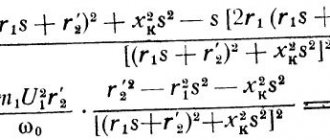
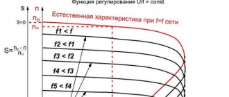
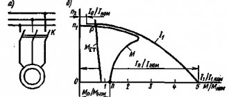
The frequency of the rotor current is directly proportional to its inductive reactance. Thus, the dependence of the current in the rotor on the sliding of the IM appears. The torque of the electric motor depends on the value of S, as it is determined by the values of the magnetic flux, current, and the shift angle between the emf and the rotor current.
Therefore, for a detailed study of the characteristics of blood pressure, the relationship shown in the figure above is established. Thus, the change in torque (at different slip values) in an IM with a wound rotor can be regulated by introducing resistance into the circuit of the rotor windings. In electric motors with a squirrel-cage rotor, the torque is regulated either using frequency converters or using motors with variable characteristics.
At rated motor load, the slip value will be in the range of 8%-2% (for small and medium power motors), rated slip.
As the load on the shaft (torque on the shaft) increases, the slip will increase; in simple terms, the magnetic field of the rotor will lag (slow down) more and more behind the magnetic field of the stator. An increase in slip (S) will lead to a proportional increase in the rotor current, therefore, the torque will increase proportionally. But at the same time, active losses in the rotor increase (resistance increases), which reduce the increase in current strength, so the torque increases more slowly than slip.
At a certain amount of slip, the torque will reach its maximum value and then begin to decrease. The value at which the moment will be maximum is called critical (Scr).
In graphical form, the mechanical characteristics of an asynchronous electric motor can be expressed using the Kloss formula:
where Mk is the critical moment, which is determined by the critical slip of the electric motor.
The schedule is based on the characteristics specified in the blood pressure passport. If questions arise regarding the drive, this graph is used as a propulsion device using an asynchronous electric motor.
The critical moment determines the amount of permissible instantaneous overload of the electric motor. When a more critical moment develops (hence, more critical sliding), the so-called stalling of the electric motor occurs and the engine stops. Rollover is one of the emergency modes.
Restoring winding markings
More precisely, marking the windings is needed only to determine the direction of winding of the winding coils. The end and beginning of the winding are designated for this purpose only. The fact is that when the winding is turned on, eddy currents begin to appear in it, which move in the direction “from beginning to end”. If the windings are connected according to the principle “beginning with beginning, end with end,” then the currents will be summed up, the windings will turn into one large resistor and a huge total current will arise. The engine will start to make a loud noise and will not turn over. The windings will start to heat up very quickly and the motor will burn out. Moreover, it is quite possible that a real flame of orange-blue color will break out with a very harmful and unpleasant odor.
There is a way to determine the ends and beginnings of windings.
This whole process is shown very well in the video. The author of this video used a mains voltage of 220 Volts to test, which I highly do not recommend doing. Use step-down transformers or an autotransformer.
Measurement methods
There are several ways to measure the slip of an induction motor. If the rotation speed differs significantly from synchronous, then it can be measured using a tachometer or tachogenerator connected to the EM shaft.
The measurement option using the stroboscopic method using a neon lamp is suitable for slip values of no more than 5%. To do this, a special line is either marked with chalk on the motor shaft, or a special stroboscopic disk is installed. They are illuminated with a neon lamp, and the rotation is counted for a certain time, then calculations are made using special formulas. It is also possible to use a full-fledged strobe, similar to the one shown below.
Preventing Electric Arc Flashes
The first step in arc flash safety is minimizing the risk of an occurrence. This can be done by performing an electrical risk assessment, which can help determine where the biggest hazards are located on site. IEEE 1584 is a good option for most sites and will help identify common problems.
Regular inspections of all high voltage equipment and all wiring is another important step. If there are any signs of corrosion, damaged wires or other problems, they should be repaired as soon as possible. This will help keep electrical currents safely inside machines and wires.
Some specific areas that should be inspected include any electrical distribution panels, control panels, control panels, outlet housings, and motor control centers.
Where does friction come from?
Friction occurs for two reasons:
- All bodies have roughness. Even very well polished metals show irregularities in an electron microscope. Absolutely smooth surfaces exist only in the ideal world of problems in which friction can be neglected. It is the elastic and inelastic deformations of irregularities upon contact of rubbing surfaces that form the friction force.
- Electromagnetic forces of attraction and repulsion act between the atoms and molecules of the surfaces of bodies Thus, the friction force is of an electromagnetic nature.
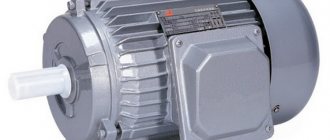
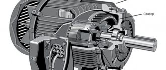
Asynchronous motor device
The main parts of the engine: stator and rotor. Three windings are located on the poles of a ring-shaped iron core; the networks of the so-called three-phase current 0 are located one relative to the other strictly at an angle of 120 degrees. We also note that inside the core itself, a cylinder made of high-quality metal is fixed on the same axis. It's called a rotor.
What does an asynchronous electric motor consist of?
Stator
The stator is a stationary part that forms a rotating magnetic field. It is this field that directly comes into contact with the electromagnetic field of the most moving part, called the rotor, thereby causing full rotation of the rotor.
Stator device
- The first is a body made of cast iron, but aluminum bodies are often found.
- Next comes the core of plates, which are made of electrical steel with a thickness of 0.5 millimeters. The core plates are fastened with brackets or seams, covered with insulating varnish, and secured in the frame with locking bolts.
- Well, the last thing in the stator design is the windings, shifted towards each other by 120 degrees, as a rule, there are no more than three of them in the device, they are inserted into grooves on the inside of the core itself, made of insulated copper, aluminum wire of round/square cross-section.
Stator core
Performed with a fit on the shaft, without an intermediate sleeve. The core fit is used in engines with a direct axis height of 250 millimeters without a key. In large engines, the cores are secured to the shaft using a key. If the rotor has a diameter of 990 millimeters, the core is blended from different segments.
Stator winding and motor speed
The number of revolutions of an electric motor can only be determined using the winding. There is nothing complicated about this and just follow the instructions and everything will work out. To do this you need:
- Remove the cover from the engine.
- Find one of the sections and see how much space it takes up around the circumference of the circle itself. For example, if the coil takes up half a circle - that's 180 degrees, then the engine runs at 3000 rpm.
- If there are three 120 degree sections in a circle, then it is a 1500 rpm engine.
- If the coil holds 4 sections at 90 degrees, then the motor is 3000 rpm.
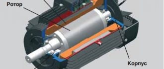
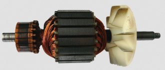
Rotor
It rotates inside the stator itself (we described above what it is). The rotor is an element of an electric motor. Its shaft is connected to the parts of the aggregators. If we talk about a massive rotor, it is a solid steel cylinder that is placed inside the stator with a core not attached to its surface (we also described above what a core is).
There are also other types of rotor:
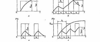
Application of high-slip motors
The main advantage of high-slip units is the ability to work with heavy loads, with uneven pulsating (shock) loads, as well as in intermittent mode with frequent starts and stops (modes S2, S3, S4, S6). Under such normal conditions, a standard engine may burn out, because... it is designed to handle infrequent stops and starts. Otherwise, such electric motors are almost completely similar to standard models of general industrial motors.
Electric motors with increased slip are used to drive mechanisms with pulsating loads (for example, low-power piston compressors) and with shock loads (hammers, pressing equipment), as well as to drive lifting and transport machines.