4.2
Average rating: 4.2
Total ratings received: 285.
4.2
Average rating: 4.2
Total ratings received: 285.
From the course of physics it is known that the effect of a magnetic field on moving charges and on a conductor with current is the appearance of the Lorentz or Ampere force. Unlike most other forces, the direction of action of these forces does not coincide with the direction of action of the field that generated them. Therefore, a special mnemonic rule was formulated - the left-hand rule. Let's briefly look at the procedure for applying this rule and look at typical examples.
Lorentz and Ampere forces
A magnetic field is generated by moving electric charges. And in turn, electric charges moving in a magnetic field experience force from it.
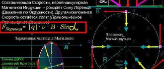
The force acting on a moving charge is called the Lorentz force.
Rice. 1. Lorentz force.
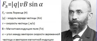
The modulus of the Lorentz force is equal to:
$$F_L = qvB sin \alpha$$
Where:
- $F_L$ is the magnitude of the Lorentz force;
- $q$ is the magnitude of the moving charge;
- $v$ is the speed of charge movement;
- $B$ is the magnetic field induction;
- $\alpha$ is the angle between the velocity and induction vectors.
Since electric current is the ordered movement of electric charges, when it flows through a magnetic field, the Lorentz forces acting on individual carriers add up to one common force, which is called the Ampere force.
Rice. 2. Ampere power.
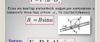
The ampere force modulus is determined using a formula similar to the Lorentz force formula:
$$F_A= I Δl B sin \alpha$$
Where:
- $F_ A$ is the magnitude of the Ampere force;
- $I$ is the current strength in the conductor;
- $Δl$ is the length of the conductor;
- $B$ is the magnetic field induction;
- $\alpha$ is the angle between the current and induction vectors.
The similarity of the formulas is explained by the fact that the Ampere force is a macroscopic manifestation of the Lorentz force. The direction of action of these forces coincides.
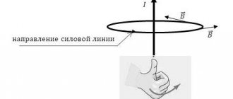
The gimlet rule is short and clear
Schematic representation of the gimlet rule
In electrical engineering, the PB shows the direction of the LMI in relation to the vector of the electric current passing in the conductor, and vice versa - it determines the path of the electric current in the coil in relation to the vector of the LMI.
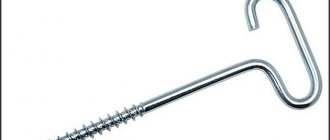
For an experimental understanding, you need to take a corkscrew or a screw with a right-hand thread and first tighten it, and then unscrew it. In the first case, this will happen clockwise and the screw (corkscrew) will move up, and in the second case, the rotation will be counterclockwise and the screw (corkscrew) will move down. Accordingly, the direction of the current will follow the behavior of the screw: up in the first case and down in the second case (shown by the arrow).
Direction of Lorentz and Ampere forces
Note that in both cases, force occurs only when the velocity vector of the charges and the magnetic induction vector are not parallel.
It is known from geometry that two non-parallel vectors plotted from one point uniquely define a plane. The peculiarity of the Lorentz and Ampere forces is that these forces are always directed perpendicular to this plane.
This fact is easy to remember. The problem is that the perpendicular to the plane can be laid in two directions. How to determine the right direction? Let's look at the left hand rule.
Motion of a charged particle in a magnetic field
In the simplest case, that is, when the magnetic induction and particle velocity vectors are orthogonal, the Lorentz force, being perpendicular to the velocity vector, can only change its direction. The magnitude of the speed, and therefore the energy, will remain unchanged. This means that the Lorentz force acts by analogy with the centripetal force in mechanics, and the particle moves in a circle.
In accordance with Newton's II law (), the radius of rotation of a particle can be determined:
.
It is necessary to note that with a change in the specific charge of the particle (), the radius also changes.
In this case, the period of rotation is T = = . It does not depend on speed, which means that the relative position of particles with different speeds will remain unchanged.
In a more complex case, when the angle between the particle velocity and the magnetic field strength is arbitrary, it will move along a helical trajectory - translationally due to the velocity component directed parallel to the field, and along a circle under the influence of its perpendicular component.
Left hand rule
The left hand rule goes like this.
If you position your left hand so that the four fingers are directed in the direction of movement of the positive charge (or in the direction of the current), and the lines of magnetic induction enter the palm, “piercing” it, then the thumb will show the direction of the Lorentz force (or Ampere force).
How to use this rule? Let's look at examples.
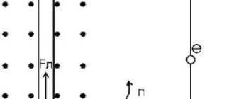
Let's say current flows through a conductor from left to right. And the lines of magnetic induction are directed upward.
Point your left hand with four fingers to the right. The palm should “look” down, so that the lines of magnetic induction enter the palm and “pierce” it. The extended thumb will indicate the direction backwards.
This will be the direction of the Ampere force in this case. Indeed, the plane formed by the vectors of current and magnetic induction is vertical, and the Ampere force is perpendicular to it.
Another example. The electron moves back, “toward the observer,” between the poles of the magnet, with the north one being on the right.
The lines of magnetic induction are directed from right to left, therefore, the palm of the left hand should be directed to the right. The electron is negatively charged, that is, four fingers of the hand should be directed against its movement - forward. The extended thumb will point upward. This will be the direction of the Lorentz force in this case.
Rice. 3. Left hand rule.
Gimlet's rule
In practice, this rule is quite convenient for determining such a magnetic field value as the direction of intensity. This rule can be used provided that the magnetic field is located directly to the current-carrying conductor. With its help, you can determine various physical quantities (moment of force, impulse, magnetic induction vector) without the presence of specialized instruments.
This rule is:
- explains the peculiarities of electromagnetism;
- explains the physics of the movement of magnetic fields accompanying it.
The formulation of the gimlet rule is as follows: if a gimlet with a right-hand thread is screwed along a current line, then the direction of the magnetic field coincides with the direction of the handle of this gimlet.
The basic principle used in the screw rule is the choice of directionality for bases and vectors . Often in practice it is determined to use the right basis. Left bases are used extremely rarely, in cases where using the right one is inconvenient or generally impractical. This principle also applies to the solenoid.
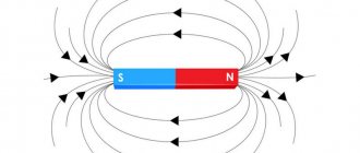
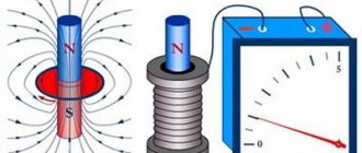
A solenoid is a coil with tightly connected turns. The main requirement is the length of the coil, which should be significantly larger than its diameter.
The solenoid rings resemble the field of a continuous magnet. The magnetic needle, being in free rotation and located next to the current conductor, will form a field and rush to occupy a vertical position passing along the conductor.
In this case, it sounds like this: if you grasp the solenoid in such a way that your fingers point to the direction of the current in the screws, then the protruding capital finger of your right hand will show the direction of the magnetic induction rows.
Various interpretations of the gimlet rule suggest that all its descriptions are adapted to different cases of their application.
The rule of the right hand says the following : having covered the element that is being examined in such a way that the fingers of a clenched fist show the vector of magnetic lines, when moving forward along the magnetic lines, the upper finger bent 90 degrees relative to the palm of the hand will show the direction of current movement.
In the case where a moving conductor is given, the principle will have the following formulation: place the hand so that the field lines enter vertically into the palm; the leading finger of the hand, positioned vertically, will orient the direction of movement of this conductor; in this case, the four remaining fingers exposed will have the same direction as the induced current.
Its use is inherent in the calculation of coils in which an influence on the current is formed, which entails the formation of a countercurrent when necessary.
A consequence of this principle is also applicable in real life: if you place the palm of your right hand so that the lines of the magnetic force field enter this palm, and point your fingers at the line of movement of charged particles along the protruding upper finger, then it is possible to indicate where the line of this force will be directed, exerting a biasing effect on the conductor. In other words, a force that makes it possible to rotate the torque on the shaft of any motor operating with electric current.
Literature
- Aksenovich L. A. Physics in secondary school: Theory. Tasks. Tests: Textbook. allowance for institutions providing general education. environment, education / L. A. Aksenovich, N. N. Rakina, K. S. Farino; Ed. K. S. Farino. - Mn.: Adukatsiya i vyakhavanne, 2004. - P. 321-322, 324-327.
- Zhilko, V.V. Physics: textbook. allowance for 11th grade. general education institutions with Russian language training with a 12-year period of study (basic and advanced levels) /V. V. Zhilko, L. G. Markovich. — 2nd ed., revised. — Minsk: Nar. Asveta, 2008. - pp. 157-164.
Special rules
Let's consider variants of the main gimlet rule for special cases. The use of such rules often simplifies the calculation process.
For a cross product
Arrange the vectors so that their starting points coincide. For this situation, the gimlet rule sounds like this:
If one of the factor vectors is rotated in the shortest way until the directions coincide with the second vector, then the gimlet rotated in a similar way will be screwed in the direction where the vector product points.
According to the clock face
When the vectors are located by matching their starting points, you can determine the direction of the product vector using a clockwise direction. To do this, you need to mentally move one of the factor vectors along the shortest path towards another vector. Then, if you look from the direction of rotation of this vector clockwise, the axial vector will be directed deep into the dial.
Right hand rules for product of vectors
There are two versions of the rule.
First option:
If the bent fingers of the right hand are directed towards the shortest path to combine the factor vector with another factor (the vectors come from one point), then the thumb moved to the side will indicate the direction of the axial vector.
Second option:
If the right palm is positioned in such a way that the thumb coincides with the first multiplier vector, and the index finger coincides with the second, then the middle finger moved to the side will coincide with the direction of the product vector.
For bases
The rules listed above also apply to bases.
For example, the gimlet rule for the right basis can be written as follows:
When you rotate the handle of the gimlet and the vectors so that the first basis vector tends to the second along the shortest path, the corkscrew will screw towards the third basis vector.
These rules are universal. They can be rewritten for mechanics to define vectors:
- mechanical rotation (determination of angular velocity);
- moment of applied forces;
- moment of impulse.
The gimlet rules also apply to Maxwell's equations, which enhances their universality.
Explanation of the name
The phenomenon of electromagnetic induction
After studying the general principles and formulations, using the rules discussed is not difficult. Below we present in detail the techniques that are used when working with electrical circuits. In particular, they are used to determine the direction of the current. If necessary, clarify the parameters of the formed field.
Similar technologies can be used in mechanics to estimate angular velocity and other operating parameters of a system. Only individual components of the formulas are changed. Algorithms for using technology remain unchanged.
Video
And in conclusion, a short video lesson about the power of Ampere.
Author: Pavel Chaika, editor-in-chief of Poznavaika magazine
When writing the article, I tried to make it as interesting, useful and high-quality as possible. I would be grateful for any feedback and constructive criticism in the form of comments on the article. You can also write your wish/question/suggestion to my email [email protected] or Facebook, with respect, the author.
Author page
Why is the gimlet rule used?
It is known that electric current is the directed movement of elementary particles that carry a charge of electricity along electrically conductive conductors. Magnetic fields around a conductor
If we take a source of electromotive force (EMF) with a current flowing through a wire of a closed circuit, that is, from “plus” to “minus”, then in the environment of the conductor there are magnetic circuits rotating in a certain circle, the configuration of which is important. These spinning fields interact with each other and can attract or repel conductors towards or away from them. And it depends on how and in which direction the magnetic fields rotate.
The nature of this relationship was formulated by Ampere in the form of a law, which became the basis for the emergence of electric motors. Without knowledge of the PB (gimlet rule), it would be impossible to invent an electric motor. This is the experimental application of the rule.
When calculating induction coils, the use of PB is characteristic, namely, taking into account the side in which the vortex is directed, it will be possible to influence the moving current, including creating a countercurrent if necessary.
Ampere's law
So, let's formulate Ampere's law: in parallel conductors, where electric currents flow in one direction, an attractive force appears. And in conductors, where currents flow in opposite directions, on the contrary, a repulsive force arises. If we speak in simple everyday language, Ampere’s law can be formulated extremely simply: “opposites attract,” and in real life (and not just in physics) we observe a similar phenomenon, don’t we?
But let’s return to physics, where Ampere’s law is also understood as the law that determines the force of the magnetic field on that part of the conductor through which current flows.
A little history
The first attempts to describe electromagnetic force were made back in the 18th century. Scientists Henry Cavendish and Tobias Mayer proposed that the force on magnetic poles and electrically charged objects obeys the inverse square law. However, the experimental proof of this fact was not complete and convincing. It was only in 1784 that Charles Augustine de Coulomb, using his torsion balance, was able to finally prove this assumption.
In 1820, the physicist Oersted discovered the fact that a volt current acts on the magnetic needle of a compass, and Andre-Marie Ampere in the same year was able to develop a formula for the angular dependence between two current elements. In fact, these discoveries became the foundation of the modern concept of electric and magnetic fields. The concept itself was further developed in the theories of Michael Faraday, especially in his idea of lines of force. Lord Kelvin and James Maxwell added detailed mathematical descriptions to Faraday's theories. In particular, Maxwell created the so-called “Maxwell field equation” - which is a system of differential and integral equations that describe the electromagnetic field and its relationship with electric charges and currents in vacuum and continuous media.
JJ Thompson was the first physicist to try to derive from Maxwell's field equation the electromagnetic force that acts on a moving charged object. In 1881, he published his formula F = q/2 vx B. But due to some miscalculations and an incomplete description of the bias current, it turned out to be not entirely correct.
And finally, in 1895, the Dutch scientist Hendrik Lorentz derived the correct formula, which is still used today, and also bears his name, just as the force that acts on a flying particle in a magnetic field is now called the “Lorentz force.”