Why was the Volksturm named the best metal detector? The main thing is that the scheme is really simple and really working. Of the many metal detector circuits that I have personally made, this is the one where everything is simple, thorough and reliable! Moreover, despite its simplicity, the metal detector has a good discrimination scheme - determining whether iron or non-ferrous metal is in the ground. Assembling the metal detector consists of error-free soldering of the board and setting the coils to resonance and to zero at the output of the input stage on the LF353. There is nothing super complicated here, all you need is desire and brains. Let's look at the design of the metal detector and the new improved Volksturm circuit with a description.
Since questions arise during the assembly process, in order to save you time and not force you to flip through hundreds of forum pages, here are the answers to the 10 most popular questions. The article is in the process of being written, so some points will be added later.
1. The operating principle and target detection of this metal detector? 2. How to check if the metal detector board is working? 3. Which resonance should I choose? 4. Which capacitors are better? 5. How to adjust resonance? 6. How to reset the coils to zero? 7. Which wire is better for coils? 8. What parts can be replaced and with what? 9. What determines the depth of target search? 10. Volksturm metal detector power supply?
How the Volksturm metal detector works
I will try to briefly describe the principle of operation: transmission, reception and induction balance. The search sensor of the metal detector contains 2 coils – transmitting and receiving. The presence of metal changes the inductive coupling between them (including the phase), which affects the received signal, which is then processed by the display unit. Between the first and second microcircuits there is a switch controlled by pulses of a generator phase-shifted relative to the transmitting channel (i.e. when the transmitter is working, the receiver is turned off and vice versa, if the receiver is turned on, the transmitter is resting, and the receiver calmly catches the reflected signal in this pause).
So, you turned on the metal detector and it beeps. Great, if it beeps, it means many nodes are working. Let's figure out why exactly it beeps. The generator on the u6B constantly generates a tone signal. Next, it goes to an amplifier with two transistors, but the amplifier will not open (it will not let a tone pass) until the voltage at the output u2B (7th pin) allows it to do so. This voltage is set by changing the mode using this same thrash resistor. They need to set the voltage so that the amplifier almost opens and passes the signal from the generator. And the input couple of millivolts from the metal detector coil, having passed through the amplification stages, will exceed this threshold and it will finally open and the speaker will beep.
Now let's trace the passage of the signal, or rather the response signal. At the first stage (1-у1а) there will be a couple of millivolts, up to 50. At the second stage (7-у1B) this deviation will increase, at the third (1-у2А) there will already be a couple of volts. But there is no response everywhere at the outputs.
Design and principle of operation of the device
Metal detectors on the market operate on different principles. Many believe that they use the principle of pulse echo or radar. Their difference from locators lies in the fact that the transmitted and received signals act constantly and simultaneously; in addition, they operate at the same frequencies.
The principle of operation of the metal detector
Devices operating on the “receive-transmit” principle record the signal reflected (re-emitted) from a metal object. This signal appears due to the exposure of a metal object to an alternating magnetic field generated by the metal detector coils. That is, the design of devices of this type provides for the presence of two coils, the first is transmitting, the second is receiving.
Metal detector circuit
Devices of this class have the following advantages:
- simplicity of design;
- Great potential for detecting metallic materials.
At the same time, metal detectors of this class have certain disadvantages:
- metal detectors can be sensitive to the composition of the soil in which they search for metal objects.
- technological difficulties in the production of the product.
In other words, devices of this type must be configured with your own hands before work.
Other devices are sometimes called beat metal detectors. This name comes from the distant past, more precisely from the times when superheterodyne receivers were widely used. Beating is a phenomenon that becomes noticeable when two signals with similar frequencies and equal amplitudes are summed. The beat consists of pulsating the amplitude of the summed signal.
The signal pulsation frequency is equal to the difference in the frequencies of the summed signals. By passing such a signal through a rectifier, it is also called a detector, and the so-called difference frequency is isolated.
This scheme has been used for a long time, but nowadays it is not used. They were replaced by synchronous detectors, but the term remained in use.
A beat metal detector works using the following principle - it registers the difference in frequencies from two generator coils. One frequency is stable, the second contains an inductor.
The device is configured with your own hands so that the generated frequencies match or at least are close. As soon as metal enters the action zone, the set parameters change and the frequency changes. The frequency difference can be recorded in a variety of ways, from headphones to digital methods.
Devices of this class are characterized by a simple sensor design and low sensitivity to the mineral composition of the soil.
But besides this, when using them, it is necessary to take into account the fact that they have high energy consumption.
Typical design
The metal detector includes the following components:
- The coil is a box-type structure that houses the signal receiver and transmitter. Most often, the coil has an elliptical shape and polymers are used for its manufacture. A wire is connected to it connecting it to the control unit. This wire transmits the signal from the receiver to the control unit. The transmitter generates a signal when metal is detected, which is transmitted to the receiver. The coil is installed on the lower rod.
- The metal part on which the reel is fixed and its angle of inclination is adjusted is called the lower rod. Thanks to this solution, a more thorough examination of the surface occurs. There are models in which the lower part can adjust the height of the metal detector and provides a telescopic connection to the rod, which is called the middle one.
- The middle rod is the unit located between the lower and upper rods. Devices are attached to it that allow you to adjust the size of the device. On the market you can find models that consist of two rods.
- The top rod usually has a curved appearance. It resembles the letter S. This shape is considered optimal for attaching it to the hand. An armrest, a control unit and a handle are installed on it. The armrest and handle are made of polymer materials.
- The metal detector control unit is necessary to process the data received from the coil. After the signal is converted, it is sent to headphones or other display devices. In addition, the control unit is designed to regulate the operating mode of the device. The wire from the coil is connected using a quick release device.
Metal detector design
All devices included in the metal detector are waterproof.
It is this relative simplicity of design that allows you to make metal detectors with your own hands.
How to check if the metal detector board is working
In general, the amplifier and switch (CD 4066) are checked with a finger at the RX input contact at maximum sensor resistance and maximum background on the speaker. If there is a change in the background when you press your finger for a second, then the key and opamps work, then we connect the RX coils with the circuit capacitor in parallel, the capacitor on the TX coil in series, put one coil on top of the other and begin to reduce to 0 according to the minimum reading of the alternating current on the first leg of the amplifier U1A. Next, we take something large and iron and check whether there is a reaction to metal in the dynamics or not. Let's check the voltage at y2B (7th pin), it should change with a thrash regulator + a couple of volts. If not, the problem is in this op-amp stage. To start checking the board, turn off the coils and turn on the power.
1. There should be a sound when the sense regulator is set to maximum resistance, touch the RX with your finger - if there is a reaction, all op-amps work, if not, check with your finger starting from u2 and change (inspect the wiring) of the non-working op-amp.
2. The operation of the generator is checked by the frequency meter program. Solder the headphone plug to pin 12 of the CD4013 (561TM2), carefully removing p23 (so as not to burn the sound card). Use In-lane on the sound card. We look at the generation frequency and its stability at 8192 Hz. If it is strongly shifted, then it is necessary to unsolder the capacitor c9, if even after it is not clearly identified and/or there are many frequency bursts nearby, we replace the quartz.
3. Checked the amplifiers and generator. If everything is in order, but still does not work, change the key (CD 4066).
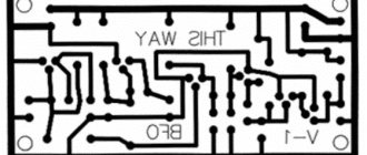
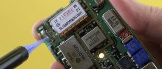
Making a printed circuit board at home
The printed circuit board can be manufactured using the technology described at: https://sdelai-sam.su/index.html#a1 The dimensions of the printed circuit board are 50mm by 75mm. Don't forget to connect the negative bus and the bottom screen layer with a jumper.
zabava.rar – download the printed circuit board in the “Dip Trace” program format.
Mirroring the board design (for printing)
Which coil resonance to choose?
When connecting the coil into series resonance, the current in the coil and the overall consumption of the circuit increases. The target detection distance increases, but this is only on the table. On real ground, the ground will be felt the more strongly, the greater the pump current in the coil. It is better to turn on parallel resonance, and increase the sense of input stages. And the batteries will last much longer. Despite the fact that sequential resonance is used in all branded expensive metal detectors, in Sturm it is parallel that is needed. In imported, expensive devices, there is a good detuning circuitry from the ground, so in these devices it is possible to allow sequential.
Rating of the TOP 15 best metal detectors of 2022
Best Inexpensive Budget Metal Detectors for Beginners
- Garrett Pro Pointer AT
- Bounty Hunter Junior
- Minelab Go-Find 44
The best metal detectors for finding coins
- Nokta&Makro Simplex Plus
- Fisher F22 11″ DD
- Minelab X-Terra 705
- Minelab Vanquish 540 Pro-Pack
The best professional metal detectors for searching for gold
- Fisher F75
- Garrett AT Gold
- XP Metal Detectors Deus
- Minelab Equinox 800
The best metal detectors by search depth by price/quality
- Garrett ACE 250 RUS
- Fisher F22 11″ DD
- XP Metal Detectors ORX
- Quest Quest Q30
How to adjust the resonance of metal detector coils
The coil, as the best option, is made from plaster floats, glued with epoxy resin from the ends to the size you need. Moreover, its central part contains a piece of the handle of this very grater, which is processed down to one wide ear. On the bar, on the contrary, there is a fork with two mounting ears. This solution allows us to solve the problem of coil deformation when tightening the plastic bolt. The grooves for the windings are made with a regular burner, then zero is set and filled. From the cold end of the TX, leave 50 cm of wire, which should not be filled initially, but make a small coil from it (3 cm in diameter) and place it inside the RX, moving and deforming it within small limits, you can achieve an exact zero, but do this It’s better outside, placing the coil near the ground (as when searching) with GEB turned off, if any, then finally fill it with resin. Then the detuning from the ground works more or less tolerably (with the exception of highly mineralized soil).
Such a reel turns out to be light, durable, little subject to thermal deformation, and when processed and painted it is very attractive. And one more observation: if the metal detector is assembled with ground detuning (GEB) and with the resistor slider located centrally, set zero with a very small washer, the GEB adjustment range is + - 80-100 mV. If you set zero with a large object - a coin of 10-50 kopecks. the adjustment range increases to +- 500-600 mV. Do not chase the voltage when setting up the resonance - with a 12V supply, I have about 40V with a series resonance. In order for discrimination to appear, we connect the capacitors in the coils in parallel (series connection is necessary only at the stage of selecting capacitors for resonance) - for ferrous metals there will be a drawn-out sound, for non-ferrous metals - a short one.
Or even simpler. We connect the coils one by one to the transmitting TX output. We tune one into resonance, and after tuning it, the other. Step by step: Connected, poked a multimeter in parallel with the coil with a multimeter at the alternating volts limit, also soldered a 0.07-0.08 uF capacitor parallel to the coil, look at the readings. Let's say 4 V - very weak, not in resonance with the frequency. We poked a second small capacitor in parallel with the first capacitor - 0.01 microfarads (0.07+0.01=0.08). Let's look - the voltmeter has already shown 7 V. Great, let's increase the capacitance further, connect it to 0.02 µF - look at the voltmeter, and there is 20 V. Great, let's move on - we'll add a couple thousand more peak capacitance. Yeah. It has already started to fall, let's roll back. And so achieve maximum voltmeter readings on the metal detector coil. Then do the same with the other (receiving) coil. Adjust to maximum and connect back to the receiving socket.
Step-by-step instructions for assembling a simple homemade metal detector with your own hands
Required tools and materials
To assemble a metal detector with your own hands you will need:
- Tools: wire cutters, knife, small saw, screwdriver, soldering iron.
- Materials: wire, solder, flux, glue, electrical tape, radio components, wooden or plastic stick.
Dielectrics (polymers, wood, glue) must be used as a rod, as well as elements for its fastening, so that they do not interfere with the operation of the metal detector.
Preparing parts
You need to prepare a board on which the electrical circuit will be mounted. Even cardboard can be used as a board. The location of future parts is marked on it by hand and holes are made.
Radio components are bought in a store or soldered from old equipment. However, you need to make sure that the details are the same. This will make it easier to coordinate the operation of the two detectors.
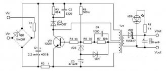
Sensitive metal detector based on a dual-circuit oscillator circuit
Manufacturing stages:
- Transistors, resistors and capacitors are placed on the board and soldered according to the diagram below.
- Solder two wires from the battery compartment, as well as two piezoelectric speakers.
- Wind the wire onto a round frame with a diameter of about 22 cm. After 10 turns, make a wire tap 20 cm long. The wire at the tap site is not torn, but folded in half by hand. Make another 20 turns. The result should be three leads 20 cm long: the beginning of the wire, the end and the outlet after the 10th turn.
- Remove the coil from the frame, holding the coils with your hands, and secure tightly with electrical tape.
- Wind a second coil, which should mirror the first. Remove it from the frame and secure it with electrical tape.
- Solder the leads of the coil detectors according to the diagram.
- Assembling the stand. The coils are placed at a distance of approximately 15 cm from each other, and a board is attached between them.
- Adjust the detectors before mounting. Turn on the metal detector and, moving the coils with your hands, achieve maximum silence. They bring metal to one of them. If the sound changes noticeably, it means the metal detector is working.
- The elements are fixed with glue and covered with oil varnish.
- Attach the handle to the stand.
On a transformer with W-shaped plates
This is a simple parametric metal detector with inductive feedback. Allows you to detect hidden wiring, reinforcement in walls and ceilings, as well as large metals in the soil. A low-power transformer is used from any radio receiver. To turn a transformer into a detector with your own hands, you need to open its magnetic circuit: remove the frame, straight jumpers and windings.
There are two schemes for converting a transformer. The first one uses old windings, the second one rewinds them.
In the first case, the W-shaped plates need to be folded together and windings put on them. Winding in diagram II is network, winding I is step-down by 12 V. Capacitor C1 adjusts the tone of the sound. Instead of the MP40 transistor, you can use KT361.
In the second case, windings of 1000 turns (in Scheme I) and 200 turns (in Scheme II) are wound on W-shaped plates. For winding I, PEL-0.1 wire is used. After 500 turns, a tap is made. Winding II is wound with PEL-0.2 wire.
The transformer is sealed and placed on the bottom rod of the metal detector. When approaching metal, the tone of the signal in the headphones will change.
On transistors
Also a simple circuit consisting of transistors K315B or K3102, capacitors, resistors, an earphone and a battery.
The first transistor creates a master oscillator, the second - a search oscillator. If you bring metal close to the coil, sound appears in the headphones. A detailed diagram is given below.
On the K561LE5 chip
The circuit consists of a microcircuit, headphones, resistors and capacitors. Coil L1 is connected to the master oscillator, and L2 is connected to the search oscillator of the microcircuit. A metal object affects the frequency of the search generator, changing the sound in the headphones. It is adjusted by MD capacitor C6. It eliminates unnecessary noise. The device supply voltage is 9 V.
Tags: sconce, throw, view, generator, house, , capacitance, like, capacitor, circuit, , magnet, metal detector, installation, setting, neutral, oscilloscope, soldering iron, variable, transfer, constant, rule, principle, check, wire, start, , work, size, regulator, resistor, row, homemade, light, network, resistance, circuit, ten, type, current, transistor, transformer, , photo, shield, effect
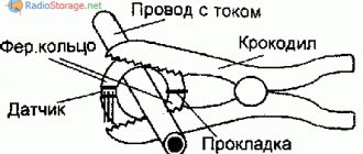
How to zero metal detector coils
To adjust the zero, we connect the tester to the first leg of the LF353 and gradually begin to compress and stretch the coil. After filling with epoxy, the zero will definitely run away. Therefore, it is necessary not to fill the entire coil, but to leave places for adjustment, and after drying, bring it to zero and fill it completely. Take a piece of twine and tie half of the spool with one turn to the middle (to the central part, the junction of the two spools), insert a piece of stick into the loop of the twine and then twist it (pull the twine) - the spool will shrink, catching the zero, soak the twine in glue, after almost complete drying adjust the zero again by turning the stick a little more and fill the twine completely.
Or simpler: The transmitting one is fixed in plastic, and the receiving one is placed 1 cm over the first one, like wedding rings. There will be an 8 kHz squeak at the first pin of U1A - you can monitor it with an AC voltmeter, but it’s better to just use high-impedance headphones. So, the receiving coil of the metal detector must be moved or shifted from the transmitting coil until the squeak at the output of the op-amp subsides to a minimum (or the voltmeter readings drop to several millivolts). That's it, the coil is closed, we fix it.
Best Inexpensive Budget Metal Detectors for Beginners
Garrett Pro Pointer AT
The smallest and brightest metal detector
- detection method – pinpointer;
- detection frequency – 11.5 kHz;
- purpose – underwater, ground;
- sensitivity setting – yes;
- ground balancing – yes;
- batteries, quantity – crown, 1.
Pros: the highest quality inexpensive pinpointer, which is sold in online stores at a price below 7,000 rubles. The device can be considered as a stand-alone device for beginning diggers, or as an addition to the main metal detector for advanced users and professionals. It does an excellent job of localizing a target during excavations with millimeter precision: in a dump of soil or in the walls of a pit.
Garrett Pro Pointer AT is the most popular pinpointer among users, with maximum ratings after use and the “Buyer’s Choice” status. Waterproof up to 3 meters, can be used underwater. Active detection area 360 degrees.
Control 3 sensitivity and detection depth modes with just one button. The bright, signature orange “carrot” color will ensure you don’t lose your Garrett Pro Pointer during excavations. Implemented light, sound and vibration notification of the target. Backlight function in case of loss.
The kit includes a mounting ring, a case for carrying the metal detector, and a set of batteries. In the rating of metal detectors, this is the lightest and cheapest device.
Cons: the kit comes with a weak battery, it is better to immediately replace it with a more powerful one.
Bounty Hunter Junior
The best gift for a child
- detection method – VLF;
- maximum detection depth – 0.5 m;
- coil design – mono;
- detection frequency – 6.5 kHz;
- sensitivity setting – no;
- tonal identification – yes;
- ground balancing – no;
- discriminator – yes;
- batteries, quantity – crown, 2.
Pros: a popular inexpensive model of a metal detector from the American company Bounty Hunter with a good search depth is perfect for children from 5 to 16 years old or novice treasure hunters. The coil of this budget metal detector is located in one block. It operates with a detection frequency of 6.5 kHz, which allows the metal detector to be used for searching at a depth of up to 0.5 m.
The distinctive characteristics of the device include the ease of setting up the metal detector and controlling it. The built-in discriminator will help distinguish metals in the soil and highlight non-ferrous metals. Sound comes from the built-in speaker.
Users note the low weight of the metal detector design – 500 grams. Considering the full range of advantages of the device and its low price in online stores, the new Bounty Hunter Junior can be considered as an excellent gift for a child for the summer.
Cons: no armrest, your arm may get tired. Afraid of water.
Minelab Go-Find 44
The best metal detector for beginners
- detection method – VFLEX;
- maximum detection depth – 0.8 m;
- detection frequency – 7.8 kHz;
- sensitivity setting – yes;
- tonal identification – yes;
- ground balancing – automatic;
- discriminator – yes;
- batteries, quantity – AA, 4.
Pros: in first place in the ranking of the best inexpensive metal detectors is a model from Minelab, a famous company among treasure hunters. The Go-Find 44 detects metals and objects using the VFLEX method, which is the company’s own development and is considered an improved version of VLF. Thanks to discrete signal processing, the number of errors is minimized.
A ground metal detector for searching for coins will be an excellent option for beginners. A durable, molded construction made of high-quality plastic will ensure long-term operation of the Go-Find 44. The device weighs just over 1 kg.
The detection frequency of 7.8 kHz allows you to find coins, lost jewelry and metal products at a depth of up to 80 cm. The information is displayed on the screen. There are 5 search modes available, headphone connection. The size of the metal detector changes and adapts to the user, from 55 to 130 cm.
Go-Find 44 runs on 4 AA batteries. Easily replaced with rechargeable batteries. One charge lasts for 40 hours. A special characteristic of the metal detector is the presence of Bluetooth; the device can be connected to a smartphone and change its settings and configurations.
Cons: not found
Which wire is better for search coils?
The wire for winding the coils does not matter. Anything from 0.3 to 0.8 will do; you still have to slightly select the capacitance to tune the circuits to resonance and at a frequency of 8.192 kHz. Of course, a thinner wire is quite suitable, it’s just that the thicker it is, the better the quality factor and, as a result, the instinct. But if you wind it 1 mm, it will be quite heavy to carry. On a sheet of paper, draw a rectangle 15 by 23 cm. From the upper and lower left corners, set aside 2.5 cm and connect them with a line. We do the same with the upper right and lower corners, but set aside 3 cm each. We put a dot in the middle of the lower part and a dot on the left and right at a distance of 1 cm.
We take plywood, apply this sketch and drive nails into all the points indicated. We take a PEV 0.3 wire and wind 80 turns of wire. But honestly, it doesn’t matter how many turns. Anyway, we will set the frequency of 8 kHz to resonance with a capacitor. As much as they reeled in, so much they reeled in. I wound 80 turns and a capacitor of 0.1 microfarads, if you wind it, say 50, you will have to put a capacitance of about 0.13 microfarads. Next, without removing it from the template, we wrap the coil with a thick thread - like how wire harnesses are wrapped. Afterwards we coat the coil with varnish. When dry, remove the spool from the template. Then the coil is wrapped with insulation - fum tape or electrical tape. Next - winding the receiving coil with foil, you can take a tape from electrolytic capacitors. The TX coil does not need to be shielded.
Remember to leave a 10mm GAP in the screen, down the middle of the reel. Next comes winding the foil with tinned wire. This wire, together with the initial contact of the coil, will be our ground. And finally, wrap the coil with electrical tape. The inductance of the coils is about 3.5 mH. The capacitance turns out to be about 0.1 microfarads. As for filling the coil with epoxy, I didn’t fill it at all. I just wrapped it tightly with electrical tape. And nothing, I spent two seasons with this metal detector without changing the settings. Pay attention to the moisture insulation of the circuit and search coils, because you will have to mow on wet grass. Everything must be sealed - otherwise moisture will get in and the setting will float. Sensitivity will worsen.
How to make "Pirate" yourself?
One of the most popular models of metal detectors designed for homemade amateur production is the “Pirate”.
This name, containing abbreviated details of its device and the developers' website, wittily reflects the romance of searching for precious metals.
Here are the main advantages of this model :
- simplicity of device and assembly;
- low cost of parts and materials;
- sufficient operating parameters;
- recognized convenience for beginners.
The electronic circuit of this model does not require programming. “Pirate” uses parts available to everyone ; a correctly assembled circuit is fully functional.
Design and operating principle
The design and layout of the “Pirate” metal detector is traditional for equipment of this kind. It is a rod with a coil an electronic unit with a battery at the top .
The location of the electronic unit should leave room for comfortable holding of the rod by hand.
Some craftsmen prefer that the sound signal from the device is supplied not by a speaker, but by headphones. In this case, the headphone cable departs from the electronic unit.
The operating technology of the device is pulsed . This allows us to provide very good sensitivity indicators for this class of equipment. Below is a diagram of an electronic unit on microcircuits.
A similar circuit can be assembled using transistors instead of microcircuits. This version may require additional settings, available only to experienced radio technicians. This is why the transistor circuit is used less frequently.
Materials, parts and blanks
In addition to the details and precision indicated on the circuit diagram of the electronic unit, to assemble a metal detector for gold and other metals, you will need to prepare some materials and workpieces:
- a ready-made board for assembling an electronic circuit or foil material for making it yourself;
- power source in the form of any combination of batteries or batteries with a total voltage of 12V;
- enamel wire with a cross section of 0.5 - 0.6 mm for making a coil;
- stranded copper wire for connections with a cross-section of at least 0.75 sq. mm;
- housing for the electronic unit - a plastic container of a suitable size;
- a fairly strong plastic pipe for the rod;
- coil winding frame;
- consumables - solder, heat-shrinkable casing, electrical tape, screws and fasteners, adhesives and sealants.
It is best to make a printed circuit board for assembling an electronic circuit based on designs presented on the Internet.
Below is one such sample , suitable for assembling electronics on microcircuits.
The manufacture of the board is carried out by amateurs of homemade electronics, and even then not all of them. Most people who want to create a metal detector themselves prefer to buy such a part.
To assemble the coil you will need a frame or frame that does not contain metal elements. An amateur craftsman can make such a frame from plywood, plastic, or select similar parameters from ready-made plastic products, for example, dishes. The frame can be purchased ready-made or made independently
Recommended coil parameters are 25 turns of enamel wire with a diameter of 0.5 mm on a mandrel with a diameter of 190-200 mm. An increase in diameter by 30% will lead to an increase in the sensitivity of the device, provided that the number of turns is reduced to 20-21.
The plastic frame for the coil is one of the most common metal detector parts on sale.
The technology for manipulating the coil is such that this very fragile unit can suffer from impacts from uneven ground, stones, and sharp objects. To avoid this, the coil on the frame is covered from below with a plastic plate . This plate not only protects the reel, but also ensures that it glides through tall grass. The search becomes more intense.
Assembly procedure and design
To successfully assemble a metal detector, it is best to follow this procedure :
- manufacture of printed circuit boards and assembly of electronic circuits;
- choosing a suitable plastic container for it and completing the assembly of the electronic unit;
- coil manufacturing;
- manufacturing a rod of a convenient shape and attaching an electronic unit and coil to it, making connections for an electronic circuit.
Although the order of assembly is not fundamental. For those who make a device for constant long-term work in the field of searching for non-ferrous metals and subsequent recycling (processing for reuse), an important factor is ease of use .
In this case, elaboration of the shape of the bar and the layout of the main elements of the apparatus becomes a key factor. Thus, a serious design phase appears in the creation of the device.
It is best to carry out this stage of the work using life-size modeling . Such modeling can be done using wooden parts of suitable shape, for example:
- shovel handle;
- plywood pieces of the desired shape;
- wood scraps;
- temporary fasteners made from pieces of wire, nails and ropes.
Having made sure that the assembled model of the device will be sufficiently functional and convenient, you can begin the final assembly. A ready-made device , as a rule, does not require configuration ; it is completely ready for use. You can start searching for metal by choosing the desired level of sensitivity and the correct tactics for manipulating the coil.
Assemblers who need to assemble their apparatus as quickly as possible
can use ready-made kits of parts .
Purchasing such a kit allows you to significantly simplify the production of “Pirate”. One of the proposals is here.
Users of the “Pirate” metal detector who have skills in amateur radio modify the design of this device. Here are just a few areas of such improvements :
- Manufacturing a coil with unusual parameters - in size, from special materials, for example - twisted pair cable.
- Installation of additional functional systems , for example, indicating the degree of battery discharge.
- Making models for underwater work .
- Additions to the electronic circuit that allow you to distinguish between metals (creation of a discrimination function).
A simple, inexpensive and reliable metal detector “Pirate” works properly in a variety of conditions.
What parts can be replaced and with what?
Transistors : BC546 – 3 pcs or KT315. BC556 – 1 piece or KT361 Op amps :
LF353 – 1 piece or exchange for the more common TL072. LM358N – 2 pcs Digital chips: CD4011 – 1 pc CD4066 – 1 pc CD4013 – 1 pc Fixed resistors, power 0.125-0.25 W: 5.6K – 1 pc 430K – 1 pc 22K – 3 pcs 10K – 1 pc 390K – 1 pc 1K – 2 pcs 1.5K – 1pc 100K – 8pcs 220K – 1pc 130K – 2pcs 56K – 1pc 8.2K – 1pc Variable resistors: 100K – 1pc 330K – 1pc Non-polar capacitors: 1nF – 1pc 22nF – 3pcs (22000pF = 22nF = 0.022uF) 22 0nF – 1 piece 1uF – 2 pieces 47nF – 1 piece 10nF – 1 piece Electrolytic capacitors: 220 µF at 16V – 2 pieces
The speaker is miniature. Quartz resonator at 32768 Hz. Two ultra-bright LEDs of different colors.
If you cannot get imported microcircuits, here are domestic analogs: CD 4066 - K561KT3, CD4013 - 561TM2, CD4011 - 561LA7, LM358N - KR1040UD1. The LF353 microcircuit has no direct analogue, but feel free to install LM358N or better TL072, TL062. It is not at all necessary to install an operational amplifier - LF353, I simply increased the gain to U1A by replacing the resistor in the negative feedback circuit of 390 kOhm with 1 mOhm - the sensitivity increased significantly by 50 percent, although after this replacement the zero went away, I had to glue it to the coil in a certain place tape a piece of aluminum plate.
Soviet three kopecks can be sensed through the air at a distance of 25 centimeters, and this is with a 6-volt power supply, the current consumption without indication is 10 mA. And don’t forget about the sockets - the convenience and ease of setup will increase significantly. Transistors KT814, Kt815 - in the transmitting part of the metal detector, KT315 in the ULF. It is advisable to select transistors - 816 and 817 with the same gain. Replaceable with any corresponding structure and power. The metal detector generator has a special clock quartz at a frequency of 32768 Hz. This is the standard for absolutely all quartz resonators found in any electronic and electromechanical watches. Including wrist and cheap Chinese wall/table ones. Archives with a printed circuit board for the Volksturm SMD version and for the Volksturm+GEB (version with manual ground detuning).
Types of MI by purpose
DIY surge protector
In accordance with their intended purpose, MI is divided into the following types:
- Soil models designed for underground surveys in the upper layers of soil. Devices in this category are the most common among metal detectors and treasure hunters who can assemble a metal detector with their own hands at home. The simplest homemade product has low accuracy and does not always distinguish between different types of metals. Professional instruments can detect small grains of gold, ignoring other metals.
- Depth models designed to detect targets at a depth of up to 6 meters. However, they can only “see” large objects with an area of over 400 square meters. see. Deep devices are in demand by engineering services as route finders, by geologists as specialized georadars for searching for native gold, etc.
- Underwater metal detecting devices operating underwater. They are subject to increased requirements for the tightness of the search system. The operating conditions of underwater MI in sea and fresh water differ significantly. Underwater detectors use only sound indication.
We recommend reading: Total power of a transformer: what it is, what parts it consists of, calculation method
Please note! Underwater MI can be used on the surface in the mode of a conventional ground metal detector. Searchers only need to adjust the length of the rod and the position of the stop to make it more convenient to use the device.
- Special metal detectors:
- security devices for detecting metal products in luggage, clothing or on a person’s body during inspection;
- industrial metal detectors as part of conveyor lines, signaling the presence of metals in products;
- military devices, collectively called mine detectors;
- detectors tuned exclusively to gold objects.
What determines the depth of target search?
The larger the diameter of the metal detector coil, the deeper the instinct. In general, the depth of target detection by a given coil depends primarily on the size of the target itself. But as the diameter of the coil increases, there is a decrease in the accuracy of object detection and sometimes even the loss of small targets. For objects the size of a coin, this effect is observed when the coil size increases above 40 cm. Overall: a large search coil has a greater detection depth and greater capture, but detects the target less accurately than a small one. The large coil is ideal for searching for deep and large targets such as treasure and large objects.
According to their shape, coils are divided into round and elliptical (rectangular). An elliptical metal detector coil has better selectivity compared to a round one, because the width of its magnetic field is smaller and fewer foreign objects fall into its field of action. But the round one has a greater detection depth and better sensitivity to the target. Especially on weakly mineralized soils. The round coil is most often used when searching with a metal detector.
Coils with a diameter of less than 15 cm are called small, coils with a diameter of 15-30 cm are called medium, and coils over 30 cm are called large. A large coil generates a larger electromagnetic field, so it has a greater detection depth than a small one. Large coils generate a large electromagnetic field and, accordingly, have greater detection depth and search coverage. Such coils are used to view large areas, but when using them, a problem may arise in heavily littered areas because several targets may be caught in the field of action of large coils at once and the metal detector will react to a larger target.
The electromagnetic field of a small search coil is also small, so with such a coil it is best to search in areas heavily littered with all sorts of small metal objects. The small coil is ideal for detecting small objects, but has a small coverage area and a relatively shallow detection depth.
For universal searching, medium coils are well suited. This search coil size combines sufficient search depth and sensitivity to targets of different sizes. I made each coil about 16 cm in diameter and placed both of these coils in a round stand from an old 15″ monitor. In this version, the search depth of this metal detector will be as follows: aluminum plate 50x70 mm - 60 cm, nut M5-5 cm, coin - 30 cm, bucket - about a meter. These values were obtained in air; in the ground it will be 30% less.
How to assemble a “Pirate” metal detector with your own hands: detailed instructions
The “Pirate” models are quite expensive, which is determined by the device’s ability to detect objects at a depth of 0.2 m (small) and 1.5 m (large). You should consider the design features and settings for metal detecting.
Materials needed to assemble a powerful metal detector with your own hands
The Pirate metal detector is considered a pulse device. To make the device, you will need to buy:
- IC KR 1006VI1 to create a transmitting unit;
- transistor IRF 740;
- IC K 157UD2 and transistor BC 547 to assemble the receiving unit;
- NPN transistors;
- PEV 0.5 wire to create a coil;
- materials to make the body, etc.;
- a plate covered with copper sheet to make a printed circuit board;
- the wire;
- electrical tape;
- soldering iron;
- scalpel;
- screwdrivers;
- pliers;
- different types of fasteners.
Assembly tools PHOTO: youtube.com
DIY metal detector circuits
The standard circuit of the “Pirate” metal detector is based on the NE555 chip. The operation of the device will depend on the comparator: 1 output is connected to the IC generator, 2 to the coil, and the output to the speaker. When detecting metal objects, a pulse from the coil will go to the comparator and then to the speaker.
The board is placed in a junction box, which can be purchased at electronics stores PHOTO: youtube.com
DIY printed circuit board
If spare parts are purchased, there is a diagram, then you need to put everything together. To place the radio components, a printed circuit board is used, which you can easily make yourself. You will need sheet getinax covered with technical copper foil.
The selected pattern is transferred to the workpiece, the tracks that connect the parts are marked, holes are drilled PHOTO: youtube.com
The tracks are coated with a protective varnish, and after drying, the board is lowered into ferric chloride for etching.
When the product is ready, it is possible to install and solder the radio components. The next stage will be checking the circuit using measuring instruments.
DIY coil for metal detector
The Pirate metal detector is considered a pulse device, so accuracy during coil assembly does not play a key role. For the base you need a ring with a diameter of 20 cm, on which 25 turns of wire are wound. To increase the depth of metal detection, the coil frame should be approximately 26-27 cm, and the number of turns should be 20-22.
Then the mandrel with the wire is thoroughly wrapped with insulation. The finished coil is placed inside a dielectric housing. You can use materials that fit the dimensions of the housing of faulty household appliances. This will make it possible to protect the coil from damage when working with the device. The ends of the winding are soldered to a stranded wire with a diameter of 0.6 mm.
Making a coil PHOTO: youtube.com
Watch this video on YouTube
How to assemble and set up a metal detector with your own hands
Each unit of the device is fixed to the metal detector rod. When the circuit is properly assembled, there is no need to adjust the device, since it immediately has high sensitivity.
More fine tuning is done using variable resistors R13. The required functioning of the metal detector is ensured with the regulator in the middle position.
Setting up a metal detector PHOTO: youtube.com
Watch this video on YouTube
How to make an underwater metal detector with your own hands
In some cases, searches are moved from the ground to water. There are, of course, special devices for functioning under water. And, in principle, you can make a deep metal detector yourself. It is necessary to take the simplest homemade device and place each unit in a hermetically sealed housing. In addition, it is necessary to slightly modify the device and install LED indicators instead of sound signals.
Underwater metal detector PHOTO: youtube.com
Watch this video on YouTube
Metal detector power supply
Separately, the metal detector circuit draws 15-20 mA, with the coil connected + 30-40 mA, totaling up to 60 mA. Of course, depending on the type of speaker and LEDs used, this value may vary. The simplest case is that power was taken from 3 (or even two) lithium-ion batteries connected in series from a 3.7 V mobile phone and when charging discharged batteries, when we connect any 12-13 V power supply, the charging current starts from 0.8 A and drops up to 50 mA per hour and then you don’t need to add anything at all, although a limiting resistor certainly wouldn’t hurt. In general, the simplest option is a 9V crown. But keep in mind that the metal detector will eat it in 2 hours. But for customization, this power option is just right. Under any circumstances, the crown will not produce a large current that could burn something on the board.
Firmware
zabava_p.rar – download the program for the microcontroller.
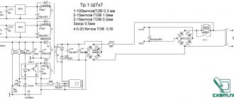
Schematic diagram of the Zabava metal detector
https://sdelai-sam.su/spravka_K561LE5.html – brief description of the K561LE5 microcircuit.
https://sdelai-sam.su/spravka_CD4001A.html – brief description of the CD4001A chip.
https://sdelai-sam.su/spravka_78L05.html – brief description of the 78L05 chip.
https://sdelai-sam.su/spravka_attiny2313.html – brief description of the ATtiny2313A microcontroller.
https://sdelai-sam.su/rezistor.html – resistors, marking of resistors, connection of resistors, etc.
https://sdelai-sam.su/kondensator.html – capacitors, marking of capacitors, connection of capacitors, etc.