You can adjust the rotation speed of the shaft of a low-power commutator motor by connecting a resistor in series to its power supply circuit. But this option creates a very low efficiency, and in addition there is no possibility of smoothly changing the rotation speed.
The main thing is that this method sometimes leads to a complete stop of the electric motor at low supply voltage. motor speed controller described in this article does not have these disadvantages. These circuits can also be successfully used to change the brightness of 12-volt incandescent lamps.
Basic functions of the speed controller
The use of such converters allows you to achieve many goals, namely:
- the possibility of stepwise acceleration and reduction of electric motor speed, which leads to reduced loads and less electrical energy consumption;
- you can carry out a smooth start, and with instantaneous maximum acceleration, the motor receives ultra-high loads, overheating the windings and other drives;
- as a means of additional protection of electronic mechanisms;
- reduction in maintenance costs for power units and pumps, as the risks of drive failures, as well as individual mechanisms, are reduced.
Welding machines, voltage stabilizers, PCs, TVs, etc. cannot do without similar built-in devices.
Operating principle of the controller
Any speed controller for a commutator motor can be built either in a separate housing or built into the tool itself. The stand-alone option makes it possible to use it, if necessary, with various tools. In any case, this does not affect the principle of operation of the regulator, i.e.:
- power from a general network of 220 Volts will be sent to the capacitor;
- the capacitor is fully charged;
- the load will then be transferred to the resistor as well as the bottom cable;
- the electrode at the thyristor (which is connected to the “+” on the capacitor) will receive the load;
- voltage charge begins to be transmitted;
- the 2nd semiconductor opens;
- the thyristor passes the load received from the capacitor;
- the capacitor is completely discharged;
- half-cycle repeat (the higher the voltage, the more often the cycle repeats).
Such homemade electronic 220V speed controllers, made by yourself, are durable, reliable, compact in size, silent, and at the same time make it possible to fine-tune the operation of the entire drive.
Design features and operating principle of the frequency converter
Electronic frequency converters are used to control the operation of electric motors in both a three-phase 380V and single-phase 220V power supply. Their work is based on changing the amplitude and frequency of the electrical signal, which allows you to smoothly change the parameters of the rotor speed of the power unit. The design of most such devices, as a rule, is based on semiconductor-type transistors with pulse-width modulators. Speed adjustment is carried out using a control unit installed on the microcontroller.
Frequently used in power tools and household appliances, commutator-type DC motors are distinguished by the fact that when directly connected to a 220-volt power supply, they begin to produce maximum speed. This increases the load on the drive and contributes to its rapid wear. In addition, at high rotor speeds, a lot of heat is generated, which leads to overheating of the working mechanisms, melting of windings and cables, and can also cause a short circuit. Therefore, it is highly recommended to install a power and frequency regulator here, even if control over the speed in the technical process and operation of the electrical installation is not provided.
Main parts for assembly
Before assembling the regulator, you need to stock up on the necessary elements and tools. This:
- Sufficient set of wiring.
- Diagram (taken from technical literature or the Internet).
- Soldering iron for work.
- Capacitors, thyristor, resistors, etc.
To your attention! High-quality regulation is achieved by including variable resistors in the circuits, providing a smooth (or stepwise) change in the number of revolutions.
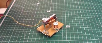
Construction and details
Now let's move on to the design of the device. Diode bridges, a capacitor, resistor R2 and diode VD6 are installed on a circuit board measuring 55x35 mm, made of foil getinax or textolite with a thickness of 1...2 mm (Fig. 9.7).
The following parts can be used in the device. Transistor - KT812A(B), KT824A(B), KT828A(B), KT834A(B,V), KT840A(B), KT847A or KT856A. Diode bridges: VD1...VD4 - KTs410V or KTs412V, VD6 - KTs405 or KTs407 with any letter index; diode VD5 - series D7, D226 or D237.
Variable resistor - type SP, SPO, PPB with a power of at least 2 W, constant - BC, MJIT, OMLT, S2-23. Oxide capacitor - K50-6, K50-16. Network transformer - TVZ-1-6 from tube TVs, TS-25, TS-27 - from the Yunost TV or any other low-power one with a secondary winding voltage of 5...8 V.
The fuse is designed for a maximum current of 1 A. The toggle switch is TZ-S or any other network switch. XP1 is a standard power plug, XS1 is a socket.
All elements of the regulator are housed in a plastic case with dimensions of 150x100x80 mm. A toggle switch and a variable resistor equipped with a decorative handle are installed on the top panel of the case. The socket for connecting the load and the fuse socket are mounted on one of the side walls of the housing.
On the same side there is a hole for the power cord. A transistor, transformer and circuit board are installed at the bottom of the case. The transistor must be equipped with a radiator with a dissipation area of at least 200 cm2 and a thickness of 3...5 mm.
Rice. Printed circuit board of a powerful 220V mains voltage regulator.
The regulator does not need to be adjusted. With proper installation and serviceable parts, it begins to work immediately after being plugged into the network.
Controller Specifications
In general, such homemade devices meet the following technical parameters:
- supported voltage range = 110 - 240 Volts;
- loads of 2.5 kW are possible;
- use of operating power within 300 W;
- It is possible to regulate the speed in the range from 9 to 99%.
If, after reading all the information, the question arises of how to make a speed controller for your engine, diagrams and tips from specialists will certainly help you figure out this essentially simple matter. Yes, and there are several ways: mounted mounting, on the surface of a printed circuit board or circuit board.
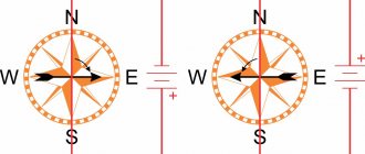
Regulating the rotation speed of the NV DPT by changing the main magnetic flux
This method of regulation in an independent excitation motor is implemented by means of a rheostat rreg in the excitation winding circuit.
Thus, as the resistance of the rheostat decreases, the magnetic flux of the field winding increases, which is accompanied by a decrease in the rotation speed [see.
(29.5)]. As rreg increases, the rotation speed increases. The dependence of the rotation speed on the excitation current is expressed by the regulating characteristic
of the motor n=f(IB) at and .
From expression (29.5) it follows that with a decrease in magnetic flux Ф
rotation frequency n increases according to a hyperbolic law (Fig. 29.5,a).
But at the same time, a decrease in Ф
leads to an increase in the armature current Ia = M/(Cm*F). During the flow, the armature current reaches a value, i.e., the voltage drop in the armature circuit reaches a value equal to half the voltage supplied to the armature. Under these conditions, the engine speed reaches a maximum nmax. With a further decrease in flow, the engine rotation speed begins to decrease, since due to the intense increase in current Ia, the second term of expression (29.9) increases faster than the first.
With a small load torque on the motor shaft, the maximum rotation speed nmax is many times higher than the rated engine speed nnom and is unacceptable in terms of the mechanical strength of the engine, i.e., it can lead to its “overrunning”. Taking this into account, when choosing a rheostat rreg, it is necessary to ensure that when its resistance is fully introduced, the engine speed does not exceed the permissible value.
For example, for engines of the 2P series, the rotation speed is allowed to exceed the nominal by no more than 2-3 times. It is also necessary to monitor the reliability of the electrical connections in the motor field winding circuit, since when this circuit is broken, the magnetic flux decreases to the value of the residual magnetism flux Fost, at which the rotation speed can reach a dangerous value. The type of adjustment characteristics n = f(Ф) depends on the value of the load torque M2 on the motor shaft: with an increase in M2, the maximum rotation speed nmax decreases (Fig. 29.5, b
)
.
Rice. 29.5. Regulating characteristics of an independent excitation motor
The disadvantage of the considered method of regulating the rotation speed is that when the magnetic flux F
the angle of inclination of the mechanical characteristics of the engine changes.
The considered method of regulating the rotation speed is simple and economical, since in independently excited motors the current IB = (0.01 - 0.07)Ia , and therefore the losses in the control rheostat are small.
However, the control range is usually nMAX/nMIN = 2 - 5 . This is explained by the fact that the lower limit of the rotation speed is due to the saturation of the machine, which limits the value of the magnetic flux Ф
, and the upper limit of the frequency is a danger of “spacing” the engine and increasing the influence of the armature reaction, the distorting effect of which, when the main magnetic flux
F
, increases and leads to sparking on the collector or to the appearance of a circular fire.
Possibilities of “weak” currents
Various children's games, robotics, and home automation use low-power motors that operate from 12-volt power supplies. The rotation speed in such devices can be adjusted by connecting a resistor in series in the circuit. But at the same time, low efficiency is achieved, and there is no possibility to smoothly change the rotation speed. Sometimes, when the voltage is low, the motor may stop completely.
A 12V speed controller made by yourself will fully comply with the necessary characteristics, although it includes a minimum of elements: a transistor, an operational amplifier, a timer and a microcircuit.
Note!
DIY furniture made from pallets (140 photos) - step-by-step master class with diagrams and drawings, design ideas
- DIY coffee table - manufacturing guide with a full description of the steps, choice of materials (120 photo ideas)
Do-it-yourself laundry basket (130 photo ideas): step-by-step master class for making it yourself, choice of materials, design options
If you plan to use stronger loads, you can take a more powerful field-effect transistor or assemble more complex systems that have increased control accuracy (with a timer).
Various circuit options allow you to create not only single-channel, but also dual-channel regulators.
PWM
The simplest method of controlling the rotation speed of a DC motor is based on the use of pulse width modulation (PWM or PWM). The essence of this method is that the supply voltage is supplied to the motor in the form of pulses. In this case, the pulse repetition rate remains constant, but their duration can vary.
The PWM signal is characterized by such a parameter as the duty cycle or duty cycle. This is the reciprocal of the duty cycle and is equal to the ratio of the pulse duration to its period.
D = (t/T) * 100%
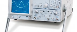
The figures below show PWM signals with different duty cycles.
With this control method, the motor rotation speed will be proportional to the duty cycle of the PWM signal.
The simplest DC motor control circuit consists of a field-effect transistor, the gate of which is supplied with a PWM signal. The transistor in this circuit acts as an electronic switch that switches one of the motor terminals to ground. The transistor opens at the moment of the pulse duration.
How will the engine behave when turned on like this? If the frequency of the PWM signal is low (several Hz), the motor will turn jerkily. This will be especially noticeable with a small duty cycle of the PWM signal. At a frequency of hundreds of Hz, the motor will rotate continuously and its rotation speed will change in proportion to the duty cycle. Roughly speaking, the engine will “perceive” the average value of the energy supplied to it.
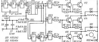
There are many circuits for generating a PWM signal. One of the simplest is a circuit based on a 555 timer. It requires a minimum of components, requires no setup and can be assembled in one hour.
The supply voltage of the VCC circuit can be in the range of 5 - 16 Volts. Almost any diodes can be used as diodes VD1 - VD3. If you are interested in understanding how this circuit works, you need to refer to the block diagram of the 555 timer. The timer consists of a voltage divider, two comparators, a flip-flop, an open collector switch and an output buffer.
The power supply (VCC) and reset pins are connected to the power supply plus, say +5 V, and the ground pin (GND) to the minus. The open collector of the transistor (DISC pin) is connected to the power supply positive through a resistor and the PWM signal is removed from it. The CONT pin is not used; a capacitor is connected to it. The THRES and TRIG comparator pins are combined and connected to an RC circuit consisting of a variable resistor, two diodes and a capacitor. The middle pin of the variable resistor is connected to the OUT pin. The extreme terminals of the resistor are connected through diodes to a capacitor, which is connected to the ground with the second terminal. Thanks to this inclusion of diodes, the capacitor is charged through one part of the variable resistor and discharged through the other. At the moment the power is turned on, the OUT pin is at a low logical level, then the THRES and TRIG pins, thanks to the VD2 diode, will also be at a low level. The upper comparator will switch the output to zero, and the lower one to one. The output of the trigger will be set to zero (because it has an inverter at the output), the transistor switch will close, and the OUT pin will be set to a high level (because it has an inverter at the input). Next, capacitor C3 will begin to charge through diode VD1. When it charges to a certain level, the lower comparator will switch to zero, and then the upper comparator will switch the output to one. The trigger output will be set to a unity level, the transistor switch will open, and the OUT pin will be set to a low level. Capacitor C3 will begin to discharge through diode VD2 until it is completely discharged and the comparators switch the trigger to another state. The cycle will then repeat. The approximate frequency of the PWM signal generated by this circuit can be calculated using the following formula:
F = 1.44/(R1*C1), [Hz]
where R1 is in ohms, C1 is in farads. With the values indicated in the diagram above, the frequency of the PWM signal will be equal to:
F = 1.44/(50000*0.0000001) = 288 Hz.
Let's combine the two circuits presented above, and we get a simple DC motor speed controller circuit, which can be used to control the engine speed of a toy, robot, micro drill, etc.
VT1 is an n-type field-effect transistor capable of withstanding the maximum motor current at a given voltage and shaft load. VCC1 is from 5 to 16 V, VCC2 is greater than or equal to VCC1. Instead of a field-effect transistor, you can use a bipolar npn transistor, a Darlington transistor, or an opto-relay of appropriate power.
Basic tips for masters
Before choosing the most effective regulator option, it is worth considering some tips:
- one of the most important criteria when choosing is power, which must exceed or correspond to the data on the device or unit used;
- for commutator motors, vector regulators are often chosen, but scalar ones are more reliable;
- the voltage must be within the permissible range;
- the wires are chosen not to be too long;
- reliable soldering of joints and good insulation;
- since the main purpose of the device is frequency conversion, this aspect is selected in accordance with certain technical requirements.
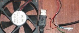
It turns out that with effort, you can reduce the noise level of a PC fan by reducing the voltage and speed using a transistor and two resistors.
This type of work on assembling a simple controller is useful for gaining additional useful skills, and it will also help save money.
Note!
Do-it-yourself illuminated mirror - step-by-step master class on how to make it yourself, photos of types of lighting
- DIY flower stand - TOP 100 photos of stand options, detailed instructions, diagrams and drawings from the masters
- Do-it-yourself furniture restoration: restoration methods, step-by-step master class, necessary tools and materials
Generalized controller circuit
An example of a controller that implements the principle of controlling a motor without power loss is a thyristor converter. These are proportional-integral circuits with feedback, which provide strict control of characteristics, ranging from acceleration-braking to reverse. The most effective is pulse-phase control: the repetition rate of the unlocking pulses is synchronized with the network frequency. This allows you to maintain torque without increasing losses in the reactive component. The generalized diagram can be represented in several blocks:
- power controlled rectifier;
- rectifier control unit or pulse-phase control circuit;
- tachogenerator feedback;
- current control unit in the motor windings.
Before delving into a more precise device and principle of regulation, it is necessary to decide on the type of commutator motor. The control scheme for its performance characteristics will depend on this.