Currently, all electronic devices contain a complex design consisting of many components. From time to time there is a need to repair such devices.
Repair usually consists of replacing faulty parts with new ones. And if earlier it was possible to simply use a soldering iron for this, then with the advent of components in BGA packages, even the use of hot-air soldering is not always successful.
Experts use an IR soldering iron or soldering station that emits infrared waves.
Description of the IR soldering process
The challenge when working with BGA components is the need to heat and melt large numbers of solder balls at once.
When they are heated, some heat is transferred to the circuit board due to the thermal conductivity of the materials. The heat provided by the soldering station is no longer enough.
Increasing the heating time or increasing the temperature does not have the best effect on the microcircuit. It may overheat and fail.
The solution suggests itself - you need to preheat the circuit board from below, without exposing the chip to heat. It can be heated either by air flow or by calm infrared radiation.
As a result, as the temperature of the board material rises, the heat dissipation from the pin legs will decrease and it will take less temperature and less exposure time to melt the solder balls.
When using infrared soldering, special devices are used for bottom heating - heat tables. This is the operating principle of an infrared soldering station.
Infrared soldering has many advantages over hot air soldering. If with hot-air soldering it is possible to control only the speed of air flow from the nozzle and the temperature of the heating element, and it is completely impossible to control the outflow of air, then with infrared soldering the temperature of the solder can be controlled throughout the entire work cycle.
The use of an infrared soldering station allows for more precise impact on a specific area of the board, which is difficult when soldering with hot air.
And during repair work, the task is precisely to replace one or more components of the circuit without affecting others at all.
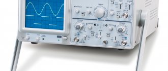
Station body
I have a PC case from a PSU. The panel is made of plexiglass; when painting, it is necessary to leave a window for the screen by gluing masking tape on both sides. The body is painted with one coat of primer and two coats of matte black spray paint. The soldering iron uses a Soviet five-pin plug from a tape recorder. The hair dryer is not disconnected; it is connected directly to the main board with pins. The soldering iron socket, hair dryer cord and power cord are located on the rear wall of the case. The front panel contains only controls, a screen, a power switch and an indicator for the hair dryer. My first design was with a panel made of textolite, with etched inscriptions, but unfortunately there are no photos left. The archive contains drawings of printed circuit boards, a drawing of a panel, a diagram in Splan and firmware.
Model IK-650 PRO
One of the most common professional-level infrared soldering stations is the IK-650 PRO. In Russia, this device was one of the first capable of successfully repairing equipment with BGA circuits.
The soldering is done so well that a strong opinion has arisen about the absolute reliability of devices whose boards were mounted using this infrared soldering station.
The software allows you to very accurately maintain the temperature profile, which is important for creating strong, reliable contacts. After all, for high-quality soldering it is necessary not only to create a temperature sufficient to melt the solder, but also to raise it smoothly and then smoothly lower it, avoiding a sharp cooling of the contact.
Only then will a strong crystal lattice be created in a drop of solder connecting the contact of the microcircuit with the mounting patch.
The infrared station has a modular design and allows you to assemble many possible configurations for preliminary and auxiliary work:
- it is possible to use various types of thermal tables;
- connecting an electron microscope;
- automatic control of heating and cooling temperatures;
- There are additional modules for restoring BGA pins (this is called reballing).
The soldering station also includes vacuum tweezers, which are convenient for installing small parts on the board.
The cost of the infrared soldering station IK-650 PRO is currently more than 150,000 rubles. It is professional equipment and, of course, is practically inaccessible for amateur use.
Parts for a homemade device
Commercially available infrared soldering stations of domestic and foreign production are very widely available on sale, but their prices start from 20,000 rubles.
And at the minimum price, it will not be a tool of the best quality. If you need to work with BGA packages in conditions of limited funds, a homemade infrared soldering station can be a solution.
It can be assembled from parts of infrared stations available for sale, as well as from scrap materials and old devices that have expired.
A heat table for a soldering station can be made from a lamp or heater with halogen lamps, which will heat the board to the required temperature. The top heater and soldering station controller will have to be purchased from spare parts, buying them new or used.
A tripod for the upper heating block can be made from the support of an old table lamp.
For the heating table, you need to stock up on halogen lamps and reflectors. They are placed in a housing that can be made independently from aluminum profiles and sheet metal.
In addition to the lamps, it is necessary to provide a place in the housing for attaching a thermocouple, which will “supply” information about the temperature of the lamps to the control module.
The temperature must be maintained precisely so that the boards do not crack from excess heat and sudden temperature changes.
List of components
To assemble the printed circuit board and housing, you will need the following components and materials:
- BQ1. Encoder EC12E24204A8
- C1. Electrolytic capacitor 35V, 10uF
- C2, C4-C9. Ceramic capacitors X7R, 0.1uF, 10%, 50V
- C3. Electrolytic capacitor 10V, 47uF
- DD1. Microcontroller ATmega8A-PU in DIP-28 package
- DA1. L7805CV 5V stabilizer in TO-220 package
- DA2. Operational amplifier LM358DT in DIP-8 package
- HG1. Seven-segment three-digit indicator with a common cathode BC56-12GWA. The board also has a seat for a cheap analogue.
- HL1. Any indicator LED for a current of 20 mA with a pin pitch of 2.54 mm
- R2,R7. Resistors 300 Ohm, 0.125W - 2 pcs.
- R6, R8-R20. Resistors 1kOhm, 0.125W - 13pcs
- R3. Resistor 10kOhm, 0.125W
- R5. Resistor 100kOhm, 0.125W
- R1. Resistor 1MOhm, 0.125W
- R4. Trimmer resistor 3296W 100kOhm
- VT1. Field effect transistor IRF3205PBF in TO-220 package
- VT2-VT4. Transistors BC547BTA in TO-92 package - 3 pcs.
- XS1. Terminal for two contacts with pin spacing 5.08 mm
- Terminal for two contacts with pin spacing 3.81 mm
- Terminal for three contacts with pin spacing 3.81 mm
- Radiator for stabilizer FK301
- Housing socket DIP-28
- Housing socket DIP-8
- Soldering iron connector
- Power switch SWR-45 BW(13-KN1-1)
- Soldering iron. We will write about it later
- Plexiglas parts for the body (cutting files at the end of the article)
- Encoder knob. You can buy it, or you can print it on a 3D printer. File for downloading the model at the end of the article
- Screw M3x10 - 2 pcs.
- Screw M3x14 - 4 pcs.
- Screw M3x30 - 4 pcs.
- Nut M3 - 2 pcs.
- M3 square nut – 8 pcs
- M3 washer - 8 pcs
- M3 locking washer – 8 pcs
- Assembly will also require installation wires, zip ties and heat shrink tubing.
This is what a set of all the parts looks like:
Set of parts for assembly of the Simple Solder MK936 soldering station
Assembly
An infrared head with a power of about 400-450 W must be mounted on a tripod using fasteners, the elements of which can be easily purchased in a retail chain; to control the temperature of the upper heating unit, a second thermocouple must be used.
It must be installed together with the heater. The cable can be laid in a flexible metal hose. The soldering station tripod must be mounted in such a way that the IR head can move freely over the entire surface.
It is necessary to provide brackets for fixing the board on the body of the thermal table. It should be located a few centimeters above halogen lamps. Suitable aluminum profiles can be used for the brackets.
The controller for the infrared soldering station is placed in a housing that can be made independently from sheet metal, preferably galvanized steel.
If necessary, you can build into the case the same cooling fans that are used in the computer case.
After assembling the structure itself, the entire circuit of the infrared soldering station will need to be debugged. This is done experimentally by repeatedly running the circuit and taking measurements. The process is not easy, but after setting it up it will give its results - the soldering station will work correctly.
Printed circuit board
The printed circuit board is single-sided with four jumpers. The PCB file can be downloaded at the end of the article.
Printed circuit board. Front side
Printed circuit board. back side
Contactless soldering iron
If there is no urgent need to use an infrared soldering station, then an infrared soldering iron can be successfully used for soldering. Outwardly, it is similar to a regular one, with the difference that instead of a sting it has a heating element.
Application and device
An infrared soldering iron is used in conditions where contact with component leads is unacceptable. It is also convenient to use it for soldering radio components, since often with a regular soldering iron carbon deposits form on the tip and the connections are of poor quality. The carbon deposits have to be cleaned off, and these actions sometimes take quite a lot of time.
In a home workshop, you can make a simple homemade infrared soldering iron from a car cigarette lighter. The heating element of this device is perfect for making tools.
Since normal operation of the cigarette lighter requires a direct current of 12 Volts, corresponding to the on-board electrical network of the car, you will need an electrical converter so that you can use a household AC network. For these purposes, you can successfully use a power supply for computer cases.
Specifications
- Powered by 12-24V DC voltage source
- Power consumption, when powered 24V: 50W
- Soldering iron resistance: 12ohm
- Time to reach operating mode: 1-2 minutes depending on supply voltage
- Maximum temperature deviation in stabilization mode, no more than 5 degrees
- Control algorithm: PID
- Temperature display on a seven-segment indicator
- Heater type: nichrome
- Temperature sensor type: thermocouple
- Temperature calibration capability
- Setting the temperature using the ecoder
- LED to display soldering iron status (heating/operating)