When repackaging lithium-ion cells of size 18650 (during battery repair) or when creating a new battery, the question arises of how to connect the banks with busbars. This is usually done by one of the methods - spot welding or soldering. Each method has its pros and cons. This way, when welding, very local and very short-term heating is created. This has a positive effect on the battery capacity - the separator does not melt during the process. The disadvantage is the small area of the contact patch, which can limit the maximum current. In some cases (assembling a laptop battery, etc.) short-term high current output is not needed, so welding is considered preferable. In other situations, the choice of method is up to the user.
Welding from a battery: is it possible?
Is welding possible with a 12 Volt battery? This question is asked by all owners of dachas and garages who still do not have a centralized power supply. Also, the voltage may simply not be enough to power an average power inverter. This is where doubts begin... On the one hand, you can remove the battery from your car and power the inverter, and then put the battery back. On the other hand, many doubts arise. What quality will the seam have? Will my inverter burn out? Is it possible to use the battery in a car later?
From our experience, we can say that welding from a battery with your own hands is quite possible. We won't say that car batteries are ideal for powering an inverter, but they can be an excellent backup option. All car batteries have a decent power reserve, so in theory they can power a simple household inverter.
DIY welding inverter
We present to your attention a diagram of a welding inverter that you can assemble with your own hands. Maximum current consumption is 32 amperes, 220 volts. The welding current is about 250 amperes, which allows you to easily weld with a 5-piece electrode, an arc length of 1 cm, which passes more than 1 cm into low-temperature plasma. The efficiency of the source is at the level of store-bought ones, and maybe better (meaning inverter ones).
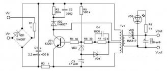
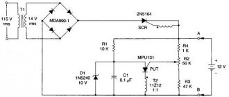
Figure 1 shows a diagram of the power supply for welding.
Fig. 1 Schematic diagram of the power supply
The transformer is wound on ferrite Sh7x7 or 8x8 The primary has 100 turns of PEV 0.3mm wire Secondary 2 has 15 turns of PEV 1mm wire Secondary 3 has 15 turns of PEV 0.2mm Secondary 4 and 5 each have 20 turns of PEV 0.35mm wire All The windings must be wound across the entire width of the frame; this gives a noticeably more stable voltage.
Fig.2 Schematic diagram of a welding inverter
Figure 2 shows a diagram of the welder. The frequency is 41 kHz, but you can try 55 kHz. The transformer at 55 kHz is then 9 turns by 3 turns, to increase the PV of the transformer.
41kHz transformer - two sets Ш20х28 2000nm, gap 0.05mm, newspaper gasket, 12vit x 4vit, 10kv mm x 30kv mm, copper tape (tin) in paper. The transformer windings are made of copper sheet 0.25 mm thick and 40 mm wide, wrapped in cash register paper for insulation. The secondary is made of three layers of tin (sandwich) separated from each other by fluoroplastic tape, for insulation between themselves, for better conductivity of high-frequency currents, the contact ends of the secondary at the output of the transformer are soldered together.
Inductor L2 is wound on a Ш20x28 core, ferrite 2000nm, 5 turns, 25 sq.mm, gap 0.15 - 0.5mm (two layers of paper from the printer). Current transformer - current sensor two rings K30x18x7 primary wire threaded through the ring, secondary 85 turns of wire 0.5 mm thick.
Welding assembly
Winding the transformer
Winding the transformer must be done using copper sheet 0.3mm thick and 40mm wide, it must be wrapped in thermal paper from a cash register 0.05mm thick, this paper is durable and does not tear as much as usual when winding a transformer.
You tell me, why not wind it with an ordinary thick wire, but it’s not possible because this transformer operates on high-frequency currents and these currents are displaced onto the surface of the conductor and the middle of the thick wire is not used, which leads to heating, this phenomenon is called the Skin effect!
And you have to fight it, you just need to make a conductor with a large surface, so thin copper sheet has this, it has a large surface along which current flows, and the secondary winding should consist of a sandwich of three copper tapes separated by fluoroplastic film, it is thinner and all these are wrapped layers in thermal paper. This paper has the property of darkening when heated, we don’t need this and it’s bad, it won’t do anything, let the main thing remain that it doesn’t tear.
You can wind the windings with PEV wire with a cross-section of 0.5...0.7 mm consisting of several dozen cores, but this is worse, since the wires are round and are connected to each other with air gaps, which slow down heat transfer and have a smaller total cross-sectional area of the wires combined compared to tin by 30 %, which can fit into the ferrite core window.
It is not the ferrite that heats up the transformer, but the winding, so you need to follow these recommendations.
The transformer and the entire structure must be blown inside the housing by a fan of 220 volts 0.13 amperes or more.
Design
To cool all powerful components, it is good to use radiators with fans from old Pentium 4 and Athlon 64 computers. I got these radiators from a computer store doing upgrades, for only $3...4 apiece.
The power oblique bridge must be made on two such radiators, the upper part of the bridge on one, the lower part on the other. Screw bridge diodes HFA30 and HFA25 onto these radiators through a mica spacer. IRG4PC50W must be screwed without mica through KTP8 heat-conducting paste.
The terminals of the diodes and transistors need to be screwed towards each other on both radiators, and between the terminals and the two radiators, insert a board connecting the 300-volt power circuit to the bridge parts.
The diagram does not indicate the need to solder 12...14 pieces of 0.15 micron 630 volt capacitors to this board into a 300V power supply. This is necessary so that the transformer emissions go into the power circuit, eliminating the resonant current surges of the power switches from the transformer.
The rest of the bridge is connected to each other by hanging installation of conductors of short length.
The diagram also shows snubbers, they have capacitors C15 C16, they should be brand K78-2 or SVV-81. You can’t put any garbage there, since snubbers play an important role: first , they dampen the resonant emissions of the transformer; second , they significantly reduce IGBT losses when turned off, since IGBTs open quickly, but close much more slowly, and during closing, capacitance C15 and C16 are charged through the VD32 VD31 diode is longer than the closing time of the IGBT, that is, this snubber intercepts all the power, preventing heat from being released on the IGBT switch three times than it would be without it. When the IGBTs open quickly, the snubbers are smoothly discharged through resistors R24 R25 and the main power is released on these resistors.
Settings
Apply power to the 15-volt PWM and at least one fan to discharge capacitance C6, which controls the relay response time.
Relay K1 is needed to close resistor R11 after capacitors C9...12 are charged through resistor R11, which reduces the current surge when the welding machine is turned on to a 220-volt network.
Without direct resistor R11, when turned on, there would be a large BAC while charging a 3000 μm 400V capacitance, which is why this measure is needed.
Check the operation of the relay closing resistor R11 2...10 seconds after power is applied to the PWM board.
Check the PWM board for the presence of rectangular pulses going to the HCPL3120 optocouplers after both relays K1 and K2 are activated.
The width of the pulses should be relative to the zero pause 44% zero 66%
Check the drivers on optocouplers and amplifiers that drive a rectangular signal with an amplitude of 15 volts and make sure that the voltage on the IGBT gates does not exceed 16 volts.
Apply 15 Volt power to the bridge to check its operation and ensure that the bridge is manufactured correctly.
The current consumption should not exceed 100mA at idle.
Verify the correct phrasing of the windings of the power transformer and current transformer using a two-beam oscilloscope.
One beam of the oscilloscope is on the primary, the second on the secondary, so that the phases of the pulses are the same, the only difference is in the voltage of the windings.
Apply power to the bridge from power capacitors C9...C12 through a 220 volt 150..200 watt light bulb, having previously set the PWM frequency to 55 kHz, connect an oscilloscope to the collector-emitter of the lower IGBT transistor, look at the signal shape so that there are no voltage surges above 330 volts as usual.
Start lowering the PWM clock frequency until a small bend appears on the lower IGBT switch indicating oversaturation of the transformer, write down this frequency at which the bend occurred, divide it by 2 and add the result to the oversaturation frequency, for example, divide 30 kHz oversaturation by 2 = 15 and 30 + 15 = 45 , 45 this is the operating frequency of the transformer and PWM.
The current consumption of the bridge should be about 150 mA and the light bulb should barely glow; if it glows very brightly, this indicates a breakdown of the transformer windings or an incorrectly assembled bridge.
Connect a welding wire at least 2 meters long to the output to create additional output inductance.
Apply power to the bridge through a 2200-watt kettle, and set the current on the light bulb to PWM at least R3 closer to resistor R5, close the welding output, check the voltage on the lower switch of the bridge so that it is no more than 360 volts according to the oscilloscope, and there should be no noise from the transformer. If there is one, make sure that the transformer-current sensor is correctly phased, pass the wire in the opposite direction through the ring.
If the noise remains, then you need to place the PWM board and optocoupler drivers away from sources of interference, mainly the power transformer and inductor L2 and power conductors.
Even when assembling the bridge, the drivers must be installed next to the radiators of the bridge above the IGBT transistors and no closer to the resistors R24 R25 by 3 centimeters. The driver output and IGBT gate connections must be short. The conductors going from the PWM to the optocouplers should not pass near sources of interference and should be as short as possible.
All signal wires from the current transformer and going to the optocouplers from the PWM should be twisted to reduce noise and should be as short as possible.
Next, we begin to increase the welding current using resistor R3 closer to resistor R4, the welding output is closed on the lower IGBT switch, the pulse width increases slightly, which indicates PWM operation. More current means more width, less current means less width.
the IGBT will fail .
Add current and listen, watch the oscilloscope for excess voltage of the lower key, so that it does not exceed 500 volts, a maximum of 550 volts in the surge, but usually 340 volts.
Reach the current where the width suddenly becomes maximum, indicating that the kettle cannot provide maximum current.
That's it, now we go straight without a kettle from minimum to maximum, watch the oscilloscope and listen so that it is quiet. Reach the maximum current, the width should increase, emissions are normal, no more than 340 volts usually.
Start cooking for 10 seconds at the beginning. We check the radiators, then 20 seconds, also cold and 1 minute the transformer is warm, burn 2 long electrodes 4mm transformer is bitter
The radiators of the 150ebu02 diodes noticeably warmed up after three electrodes, it’s already difficult to cook, a person gets tired, although he cooks great, the transformer is hot, and no one cooks anyway. The fan, after 2 minutes, brings the transformer to a warm state and you can cook it again until it becomes puffy.
Below you can download printed circuit boards in LAY format and other files
Evgeny Rodikov (evgen100777 [dog] rambler.ru). If you have any questions when assembling the welder, write to E-Mail.
List of radioelements
| Designation | Type | Denomination | Quantity | Note | Shop | My notepad |
| power unit | ||||||
| Linear regulator | LM78L15 | 2 | Search in the Otron store | To notepad | ||
| AC/DC converter | TOP224Y | 1 | Search in the Otron store | To notepad | ||
| Voltage reference IC | TL431 | 1 | Search in the Otron store | To notepad | ||
| Rectifier diode | BYV26C | 1 | Search in the Otron store | To notepad | ||
| Rectifier diode | HER307 | 2 | Search in the Otron store | To notepad | ||
| Rectifier diode | 1N4148 | 1 | Search in the Otron store | To notepad | ||
| Schottky diode | MBR20100CT | 1 | Search in the Otron store | To notepad | ||
| Protection diode | P6KE200A | 1 | Search in the Otron store | To notepad | ||
| Diode bridge | KBPC3510 | 1 | Search in the Otron store | To notepad | ||
| Optocoupler | PC817 | 1 | Search in the Otron store | To notepad | ||
| C1, C2 | Electrolytic capacitor | 10uF 450V | 2 | Search in the Otron store | To notepad | |
| Electrolytic capacitor | 100uF 100V | 2 | Search in the Otron store | To notepad | ||
| Electrolytic capacitor | 470uF 400V | 6 | Search in the Otron store | To notepad | ||
| Electrolytic capacitor | 50uF 25V | 1 | Search in the Otron store | To notepad | ||
| C4, C6, C8 | Capacitor | 0.1uF | 3 | Search in the Otron store | To notepad | |
| C5 | Capacitor | 1nF 1000V | 1 | Search in the Otron store | To notepad | |
| C7 | Electrolytic capacitor | 1000uF 25V | 1 | Search in the Otron store | To notepad | |
| Capacitor | 510 pF | 2 | Search in the Otron store | To notepad | ||
| C13, C14 | Electrolytic capacitor | 10 µF | 2 | Search in the Otron store | To notepad | |
| VDS1 | Diode bridge | 600V 2A | 1 | Search in the Otron store | To notepad | |
| NTC1 | Thermistor | 10 ohm | 1 | Search in the Otron store | To notepad | |
| R1 | Resistor | 47 kOhm | 1 | Search in the Otron store | To notepad | |
| R2 | Resistor | 510 Ohm | 1 | Search in the Otron store | To notepad | |
| R3 | Resistor | 200 Ohm | 1 | Search in the Otron store | To notepad | |
| R4 | Resistor | 10 kOhm | 1 | Search in the Otron store | To notepad | |
| Resistor | 6.2 Ohm | 1 | Search in the Otron store | To notepad | ||
| Resistor | 30Ohm 5W | 2 | Search in the Otron store | To notepad | ||
| Welding inverter | ||||||
| PWM controller | UC3845 | 1 | Search in the Otron store | To notepad | ||
| VT1 | MOSFET transistor | IRF120 | 1 | Search in the Otron store | To notepad | |
| VD1 | Rectifier diode | 1N4148 | 1 | Search in the Otron store | To notepad | |
| VD2, VD3 | Schottky diode | 1N5819 | 2 | Search in the Otron store | To notepad | |
| VD4 | Zener diode | 1N4739A | 1 | 9V | Search in the Otron store | To notepad |
| VD5-VD7 | Rectifier diode | 1N4007 | 3 | To reduce voltage | Search in the Otron store | To notepad |
| VD8 | Diode bridge | KBPC3510 | 2 | Search in the Otron store | To notepad | |
| C1 | Capacitor | 22 nF | 1 | Search in the Otron store | To notepad | |
| C2, C4, C8 | Capacitor | 0.1 µF | 3 | Search in the Otron store | To notepad | |
| C3 | Capacitor | 4.7 nF | 1 | Search in the Otron store | To notepad | |
| C5 | Capacitor | 2.2 nF | 1 | Search in the Otron store | To notepad | |
| C6 | Electrolytic capacitor | 22 µF | 1 | Search in the Otron store | To notepad | |
| C7 | Electrolytic capacitor | 200 µF | 1 | Search in the Otron store | To notepad | |
| C9-C12 | Electrolytic capacitor | 3000uF 400V | 4 | Search in the Otron store | To notepad | |
| R1, R2 | Resistor | 33 kOhm | 2 | Search in the Otron store | To notepad | |
| R4 | Resistor | 510 Ohm | 1 | Search in the Otron store | To notepad | |
| R5 | Resistor | 1.3 kOhm | 1 | Search in the Otron store | To notepad | |
| R7 | Resistor | 150 Ohm | 1 | Search in the Otron store | To notepad | |
| R8 | Resistor | 1Ohm 1Watt | 1 | Search in the Otron store | To notepad | |
| R9 | Resistor | 2 MOhm | 1 | Search in the Otron store | To notepad | |
| R10 | Resistor | 1.5 kOhm | 1 | Search in the Otron store | To notepad | |
| R11 | Resistor | 25Ohm 40Watt | 1 | Search in the Otron store | To notepad | |
| R3 | Trimmer resistor | 2.2 kOhm | 1 | Search in the Otron store | To notepad | |
| Trimmer resistor | 10 kOhm | 1 | Search in the Otron store | To notepad | ||
| K1 | Relay | 12V 40A | 1 | Search in the Otron store | To notepad | |
| K2 | Relay | RES-49 | 1 | Search in the Otron store | To notepad | |
| Q6-Q11 | IGBT transistor | IRG4PC50W | 6 | Search in the Otron store | To notepad | |
| MOSFET transistor | IRF5305 | 8 | Search in the Otron store | To notepad | ||
| D2, D3 | Schottky diode | 1N5819 | 2 | Search in the Otron store | To notepad | |
| VD17, VD18 | Rectifier diode | VS-HFA30PA60CPBF | 2 | Search in the Otron store | To notepad | |
| VD19-VD22 | Rectifier diode | VS-150EBU02 | 4 | Search in the Otron store | To notepad | |
| VD31, VD32 | Rectifier diode | VS-HFA25PB60PBF | 2 | Search in the Otron store | To notepad | |
| VD36-VD41 | Zener diode | 1N4744A | 12 | Search in the Otron store | To notepad | |
| Optocoupler | HCPL-3120 | 2 | Search in the Otron store | To notepad | ||
| C13, C21 | Electrolytic capacitor | 10 µF | 2 | Search in the Otron store | To notepad | |
| C15-C18 | Capacitor | 6.8 nF | 4 | K78-2 or SVV-81 | Search in the Otron store | To notepad |
| C20, C22 | Electrolytic capacitor | 47uF 25V | 2 | Search in the Otron store | To notepad | |
| L2 | Inductor | 35 µH | 1 | Search in the Otron store | To notepad | |
| R12, R13, R50, R54 | Resistor | 1 kOhm | 4 | Search in the Otron store | To notepad | |
| R14, R15 | Resistor | 1.5 kOhm | 2 | Search in the Otron store | To notepad | |
| R17, R51 | Resistor | 10 ohm | 2 | Search in the Otron store | To notepad | |
| R24, R25 | Resistor | 30Ohm 20Watt | 2 | Search in the Otron store | To notepad | |
| R26 | Resistor | 2.2 kOhm | 1 | Search in the Otron store | To notepad | |
| R27, R28 | Resistor | 5Ohm 5Watt | 2 | Search in the Otron store | To notepad | |
| R36, R46-R48, R52, R42-R44 | Resistor | 5 ohm | 8 | Search in the Otron store | To notepad | |
| R45, R53 | Resistor | 1.5 Ohm | 2 | Search in the Otron store | To notepad | |
| Add all | ||||||
Attached files:
- welding.rar (495 Kb)
Tags:
- Sprint-Layout
- Welding
Personal experience of welding from a battery
We will talk about our experience in using batteries as an inverter power source. You can conduct the test yourself and repeat our steps to verify the result.
Let’s say right away that one standard 90Ah battery will not be enough. Just take it for granted. At first we tried to power the inverter from one battery. We cooked at a low current using electrodes with a diameter of 2 mm. The arc was practically not ignited, the seams were made with great difficulty. Then we took two batteries and connected them in series.
The work went a little easier, but the result was still far from ideal. The seams were made a little easier, but the arc still “walked”, burned unstably, sometimes even went out, and the whole ignition process had to be repeated again. The end result was very defective seams with lack of penetration. In this case, the electrodes strongly stuck to the metal, and their consumption increased significantly. In short, the welding was unsuccessful.
We could have given up on this idea, but there was another battery lying at the dacha and we decided to connect it to two other batteries. And this option turned out to be the most viable. When using three batteries, the power reserve is so large that, in principle, it is possible to achieve more or less stable operation of the welding machine.
We experimented with different settings, increasing and decreasing the current, and using electrodes up to 4 mm. And overall everything went well. Of course, welding from batteries is not as comfortable and simple as from a regular outlet. But if you watch the arc carefully, you can understand its behavior and adjust. Moreover, when powered by 3 batteries, the arc behaves much more stable and is easier to ignite.
During our experiment, we found out that three batteries can be used not only for welding, but also for cutting metal parts of small thickness. But the cut is not very beautiful.
By the way, do not forget to monitor the current strength. Do not set the values too high, as batteries tend to increase the final current to too high values, and you may simply burn through the metal. And in general, carefully monitor the progress of work. Because welding from a battery requires care and skill. This is the only way to make a more or less normal seam.
What is important to know
An important point is the choice of wire. If its cross-section is too large, you risk burning your batteries. Therefore, we strongly recommend using wires with a small cross-section, because it is better if the wire itself burns out (it is cheaper to replace it).
You can adjust the current strength (A) depending on the cross-section and length of the cable. The optimal length is 1 meter and cross-section 12 mm2. But, if you are making such a homemade product for the first time, try using a wire of a smaller cross-section, this will avoid possible problems.
Remember! It is prohibited to handle the electrode or wire with bare hands. Try using any available means that will help avoid direct contact.
Is it worth cooking from a battery?
Welding from car batteries is possible, but we do not recommend using this method on an ongoing basis. The only advantage of this method is the possibility of welding in the field. But there are several times more disadvantages.
The most important drawback is the almost uncontrollable current with which welding is carried out from the battery. The batteries themselves tend to increase the initial current value, and you will never know the exact values. This is inconvenient and leads to frequent defects that you cannot even prevent.
Also, due to uncontrolled current, the device may simply burn out. Our inverter survived, but if you use it ineptly, you will lose both three batteries and a welding machine. At the same time, be prepared for a large overconsumption of electrodes. When welding from batteries, you can waste a whole pack of rods when manual arc welding.
In addition, it is better not to install the battery used in this case in the car. The likelihood of problems is small, but it still exists.
Is it all worth it? Yes, if you have no way to power the device at all, but it is very necessary. But in other situations, it is better to simply buy a fuel-powered generator and use it to power the welder. In addition, you can also power other power tools, which is very convenient.
Welding machine from a car battery
Let's note it right away! Our homemade product is not safe, it can harm your health and damage car batteries, which are not considered cheap.
The essence of the homemade product: if two welding machines are connected in series, you will get a welding machine that will have two functions:
- can cut metal;
- weld metal.
For homemade products you need the following materials:
- Two car batteries. It is desirable that the current be 700 A or higher. Voltage does not play a role in this matter, because only current is involved in welding.
- You also need two wires 1 meter long. Their cross section is 12 mm2.
- An electrode that is at hand.
Safety precautions
In appearance, batteries do not pose any danger, since all their “internals” are enclosed in a durable casing. But this does not mean that you need to neglect safety precautions when using car batteries. Moreover, when connected to an inverter.
If you need to remove the battery, move it, or perform any other actions, use special gloves. Ideally, you also need to choose the right clothes, but you are unlikely to think about this while sitting in the garage. Therefore, at least have thick gloves with you. If you get electrolyte on your skin, wash it off immediately with the solution. The solution can be made from soda or ammonia with water.
After handling, remove gloves and wash your hands thoroughly with soap. Don't eat near the battery, don't smoke, and generally take this seriously. Need a break? Leave the batteries in a separate room and leave yourself.
If your batteries are dirty, they need to be cleaned. This can be done using the same solution of ammonia with water. Use a clean, dry cloth. If you removed the batteries from the car, then clean the holes in the plugs so that there are no blockages. Otherwise, there may be excess gas pressure.
And in general, remember that batteries can be a potential source of danger to your life and health. Better protect your skin from acids and electrolytes, protect your eyes and mucous membranes. Do not perform any manipulations with batteries while intoxicated. Keep a small fire extinguisher nearby just in case. After all, not only the battery, but also the inverter itself can become a source of danger.
These rules are simple and obvious, but in the process of work, most masters forget about them. And then they regret it. Be smart and prevent a lot of problems by practicing safety precautions.
Transformers (with or without rectifier)
The heart of a transformer is the core. It is assembled from transformer steel plates, which are quite problematic to make by hand. By hook or by crook, the source material is extracted at factories, construction teams, and scrap metal collection points. The resulting structure (usually in the form of a rectangle) must have a cross-section of no less than 55 cm². This is a rather heavy structure, especially after laying the windings.
During assembly, it is imperative to provide an adjusting screw, with which you can move the secondary winding relative to the stationary primary.
In order not to go into the complexity of calculating the cross-section of wires, we will take typical parameters:
Based on this, the cross-section of the primary wire should be at least 5 mm²; if you do it with a margin, you can take a wire of 6–7 mm². The insulation must be heat-resistant and made from a material that does not support combustion.
Summary
Is it possible to use welding equipment from a 12 volt car battery? It's possible, but is it worth it? To weld a short seam you will need to expend a lot of your energy, time and related materials.
To get a good result, you will need to use at least three auto batteries. It is unlikely that there will be so many undischarged batteries on the farm at once.
The welding process itself using a 12-volt battery will be inconvenient and difficult. The welding arc goes out and is difficult to ignite. The tension becomes uncontrollable.
There will be a lot of flaws as a result of the welding process. The result will be unsatisfactory. Therefore, all efforts and efforts are in vain.
So it turns out that you need to use a 12-volt car battery for welding only in the most necessary cases. We remind you that the best option is to purchase a fuel generator. An irreplaceable thing in a country house.
But you can use the battery from the car to create spot welding with your own hands.
Auto batteries make excellent units for small household jobs. Cheap, durable. But this deserves special attention. Therefore, we will tell you in the next material.
User voting
Which spot welding machine from Aliexpress would you choose or recommend?
AFABEITA D260475
0.00% ( 0 )
DH30
28.57% ( 2 )
DEKO DKA
14.29% ( 1 )
ANDELI MIG-250E
0.00% ( 0 )
Hand Kit
0.00% ( 0 )
WERT MMA 180N
0.00% ( 0 )
FORGELO AC 220V 1600W
0.00% ( 0 )
ANDELI TIG-250MPL MOS
0.00% ( 0 )
WEGA 200 miniMIG
0.00% ( 0 )
SAI190K Resanta
14.29% ( 1 )
Spot Welder
14.29% ( 1 )
RX-1
28.57% ( 2 )
XPGTool
0.00% ( 0 )
Pobeda PT-1500
0.00% ( 0 )
Plastic Welding Machine
0.00% ( 0 )
ANENG KSJ170
0.00% ( 0 )
Introductory information
In theory, everything seems much simpler. But in application, certain conditions must be met. The current in the electrical network must remain uninterrupted and not fall below 180 Volts.
Or your welding unit must cope with low voltage work. Such equipment is not cheap.
It is not even discussed that you must have access to electricity. But some country houses and dachas, garages located far from the urban area are not connected to electricity.
What to do in this case. Our opinion comes down to buying a fuel generator for welding. But not everyone wants to spend extra money, especially if you rarely use welding.
The correct option under such circumstances is to use a 12-volt car battery. Some specialists manage to connect the battery to a welding inverter.
Even to carry out non-long-term welding. In our review we will write whether it is possible to carry out welding tasks using a 12 Volt battery. Is it really necessary to take such risks?
“Russian welding”: how to properly connect batteries for welding work in the field
Field welding using car batteries is known to advanced jeep fans all over the world, but for some reason on foreign Internet forums it is called “Russian welding”, “Russian welding”... Apparently, for the severity inherent in “roller coaster” and “Russian roulette” .
– Do you have spare parts for UAZ? - Yes, what do you need? – Electrodes, wire and electrical tape... (bearded joke)
The habit of drivers of past generations to carry half a trunk of tools and half a trunk of spare parts, fortunately, is a thing of the past. A modern car with good and timely preventive maintenance, even if it is at a very advanced age, rarely presents fatal surprises, after which further movement can only be continued on a “tie” or on a tow truck. However, there is and remains a class of car enthusiasts who still vitally need to have a lot of spare parts and a solid arsenal of tools, which includes, at a minimum, a drill and an angle grinder. We are talking about owners of honest full-size frame SUVs who practice tough rally raids and serious travel to places where you can call for help only using a satellite phone...
In the regions where, according to the text of a popular Jeeper sticker, “even wolves are afraid of shit,” 80th and 100th “Cruisers”, riveted “Defs”, old “Patrols” climb, but, let’s be honest, much more often there You can find Ulyanovsk SUVs. And since the quality of parts for UAZs still leaves much to be desired, every true UAZ driver knows very well that he has to rely only on himself - on his level 80 field repair skill and a stock of hardware and tools that a car shop would envy!
You will still laugh (s), but welding occupies a very honorable place in the mobile arsenal of an advanced jeeper, and sometimes it is the only lifeline that allows you to get out of the taiga or even continue the route! A broken kingpin in the steering knuckle, a burst clamp on the outboard cardan bearing, a cracked panhard rod - it is completely unrealistic to carry every conceivable spare part with you (although I would like to!), and often it is possible to restore the car's mobility in extreme conditions with the help of welding.
Today, a wide range of mobile cordless tools are available for sale (and are becoming cheaper - systematically, although not as quickly as we would like), which until recently were firmly connected to a 220-volt power outlet. However, powering a welding machine in the field from a car’s electrical system is still extremely difficult, if not almost impossible. Yes, mobile welding machines powered by built-in lithium batteries have already appeared on the market, but the cost of under a hundred thousand rubles clearly does not contribute to their prevalence among people in the foreseeable future... And through a 12/220 volt converter, even the lowest-power 220-volt inverter welder with an electrode - a “kopeck piece” will require an exorbitant load on the battery and generator from the car’s electrical system - more than 200 amperes... And this is for a burning arc, without taking into account the jump during ignition... We recently talked about a unique Soviet gadget - a car welding machine, but this is rather an interesting technical a curiosity, and not a serious device, especially since such devices have not been produced at the factory since the 90s.
However, welding is simply vital for a jeep driver - what can you do? Everything is very simple: the solution to the problem was found by our grandfathers and is successfully used to this day. We are talking about welding using car batteries! A 12-volt car battery is a source of a fair amount of electricity with a high output current - exactly what you need for welding. To operate a two-millimeter electrode, two batteries connected in series are sufficient, and for a three-ruble electrode, three batteries are optimal. Even a single jeeper often has two batteries - a starter and one that powers the winch, but if you need to weld massive parts and require heating with a thicker electrode, the third battery is borrowed from colleagues in off-road competitions or fishing/hunting.