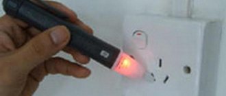
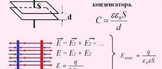
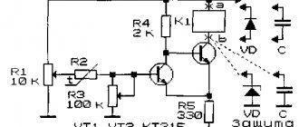
This battery charge indicator is based on an adjustable zener diode TL431. Using two resistors, you can set the breakdown voltage in the range from 2.5 V to 36 V.
I will give two schemes for using the TL431 as a battery charge/discharge indicator. The first circuit is intended for a discharge indicator, and the second for a charge level indicator.
The only difference is the addition of an NPN transistor, which will turn on some kind of signaling device, such as an LED or a buzzer. Below I will give a method for calculating resistance R1 and examples for some voltages.
Low battery indicator circuit
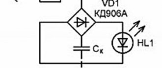
The zener diode works in such a way that it begins to conduct current when a certain voltage is exceeded on it, the threshold of which we can set using a voltage divider on resistors R1 and R2. In the case of a discharge indicator, the LED indicator should be illuminated when the battery voltage is less than required. Therefore, an NPN transistor was added to the circuit.
Silicone Soldering Mat
Size 55 x 38 cm, weight 800 g....
More details
As you can see, the adjustable zener diode regulates the negative potential, so a resistor R3 is added to the circuit, whose task is to turn on the transistor when TL431 is turned off. This resistor is 11k, selected by trial and error. Resistor R4 serves to limit the current on the LED; it can be calculated using Ohm's law.
Of course, you can do without a transistor, but then the LED will go out when the voltage drops below the set level - the diagram is below. Of course, such a circuit will not work at low voltages due to the lack of sufficient voltage and/or current to power the LED. This circuit has one drawback, which is the constant current consumption, around 10 mA.
Improving project accuracy
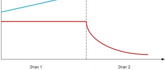
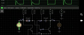
In our project, we use current and voltage detection to test battery capacity, but in our conditions this is “not perfect”. The point here is that the relationship between the actual voltage value and its value at the ADC output is not completely linear, and this circumstance introduces a small error into our measurements.
To increase the accuracy of the results obtained, you should plot the dependence of the values at the ADC output on the “accurate” (calibrated) voltage source and then use any method that, based on the values of these points, will construct an equation of a straight line that is as close as possible to these points. This equation is straight (more precisely, its slope) and will need to be used as a multiplier when converting the 0-1023 range at the ADC output to the 0-5 V range.
Also, the MOSFET transistor used in our project requires a voltage of more than 7V in order for its channel to fully open. And since we only supply 5V to it, this, accordingly, leads to some error in the results obtained. A solution could be to use the IRL520N MOSFET transistor with an N-type channel - with its help, there is no need to use a 12V supply voltage and we can directly work with the 5V logic voltage levels available on the Arduino board.
Battery charge indicator circuit
In this case, the charge indicator will be constantly on when the voltage is greater than what we defined with R1 and R2. Resistor R3 serves to limit the current to the diode.
It's time for what everyone likes best - math