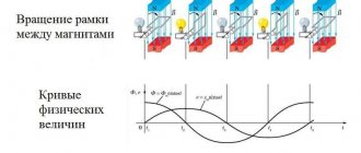
Each object is initially supplied with three-phase current. The main reason is the use in power plants of generators with three-phase windings, out of phase with each other by 120 degrees and producing three sinusoidal voltages. However, with further distribution of current, only one phase is supplied to the consumer, to which all existing electrical equipment is connected. Sometimes there is a need to use non-standard devices, for example, how to choose a capacitor for a three-phase motor. As a rule, it is necessary to calculate the capacity of a given element that ensures stable operation of the unit.
Minus symbol
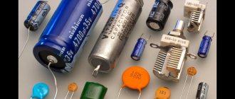
The principle of marking the polarity of imported products differs from traditional standards of the domestic industry and consists of an algorithm: “to find out where the plus is, you first need to find where the minus is.” The location of the negative contact is indicated by both special symbols and the color of the housing.
For example, on a black cylindrical body, the negative terminal side, sometimes called the cathode, has a light gray stripe applied along the entire height of the cylinder. A dashed line, or elongated ellipses, or a minus sign, as well as 1 or 2 angle brackets with an acute angle directed towards the cathode, are printed on the strip. The model range with other denominations is distinguished by a blue body and a pale blue stripe on the side of the negative contact.
Other colors are also used for marking, following the general principle: dark body and light stripe. Such markings are never completely erased and therefore you can always confidently determine the polarity of the “electrolyte,” as electrolytic capacitors are called for brevity in radio engineering jargon.
The body of SMD containers, manufactured in the form of a metal aluminum cylinder, remains unpainted and has a natural silver color, and the segment of the round upper end is painted with an intense black, red or blue color and corresponds to the position of the negative terminal. After mounting the element on the surface of the printed circuit board, the partially painted end of the housing, indicating the polarity, is clearly visible on the diagram, since it has a greater height compared to flat elements.
The polarity designation of a cylindrical SMD device corresponding to the marking is applied to the surface of the board: this is a circle with a segment shaded with white lines where the negative contact is located. However, it should be noted that some manufacturers prefer to mark the positive contact of the device in white.
How to connect
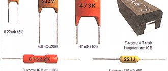
Connecting a capacitor to a circuit with direct current occurs as follows: the plus (anode) of the current source is connected to an electrode, which is covered with an oxide film. Failure to comply with this requirement may result in dielectric breakdown. It is for this reason that liquid capacitors must be connected to a circuit with an alternating current source, connecting two identical sections in counter-series series. Or apply an oxide layer to both electrodes. Thus, a non-polar electrical device is obtained that operates in both DC and DC networks. But in both cases, the resulting capacitance becomes half as much. Unipolar electrical capacitors are large in size, but can be connected to alternating current circuits. Marking is done with color and digital code. Digital markings of capacitor capacitance are shown below.
Table of digital markings of capacitor capacitance.
Model overview
There are several popular models that can be found on sale.
It is worth noting that these models differ not in capacity, but in type of design:
- Metallized polypropylene versions of the SVV-60 brand. The cost of this version is about 300 rubles.
- NTS film brands are somewhat cheaper. With the same capacity, the cost is about 200 rubles.
- E92 – products of domestic manufacturers. Their cost is small - about 120-150 rubles for the same capacity.
There are other models, often differing in the type of dielectric used and the type of insulating material.
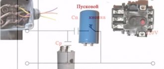
It is worth noting that on small electric motors used for domestic needs, for example, for a 200-400 W electric sharpener, you can not use a starting capacitor, but get by with one working capacitor, I have done this more than once - a working capacitor is quite enough. Another thing is if the electric motor starts with a significant load, then it is better to use a starting capacitor, which is connected in parallel with the working capacitor by pressing and holding the button while the electric motor accelerates, or using a special relay. The starting capacitor capacity is calculated by multiplying the working capacitor capacity by 2-2.5; this calculator uses 2.5.
It is worth remembering that as the asynchronous motor accelerates, it requires less capacitor capacity, i.e. You should not leave the starting capacitor connected for the entire operating time, because A large capacity at high speeds will cause overheating and failure of the electric motor.
By appearance
If the markings are worn out or unclear, determining the polarity of the capacitor is sometimes possible by analyzing the appearance of the case. In many containers with terminals located on one side and not mounted, the positive leg is longer than the negative leg. Products of the ETO brand, now obsolete, look like 2 cylinders placed on top of each other: a larger diameter and small height, and a smaller diameter, but significantly higher. The contacts are located in the center of the ends of the cylinders. The positive terminal is mounted at the end of a cylinder with a larger diameter.
Using a multimeter
Before conducting experiments, it is important to assemble the circuit so that the test voltage of the direct current source (DC) does not exceed 70-75% of the nominal value indicated on the drive case or in the reference book. For example, if the electrolyte is designed for 16 V, then the power supply should produce no more than 12 V. If the electrolyte rating is unknown, the experiment should be started with small values in the range of 5-6 V, and then gradually increase the voltage at the power supply output.
The capacitor must be completely discharged - to do this, you need to short-circuit its legs or leads for a few seconds with a metal screwdriver or tweezers. You can connect an incandescent lamp from a flashlight to them until it goes out or a resistor. Then you should carefully inspect the product - there should be no damage or swelling of the body, especially the protective valve.
The following devices and components will be required:
- IP - battery, accumulator, computer power supply or specialized device with adjustable output voltage;
- multimeter;
- resistor;
- installation accessories: soldering iron with solder and rosin, side cutters, tweezers, screwdriver;
- marker for applying polarity marks to the body of the electrolyte being tested.
Then you should assemble the electrical circuit:
- parallel to the resistor, using “crocodiles” (i.e., probes with clamps), connect a multimeter configured to measure direct current;
- connect the positive terminal of the IP to the terminal of the resistor;
- Connect the other terminal of the resistor to the contact of the capacitor, and connect its 2nd contact to the negative terminal of the IP.
If the polarity of the electrolyte connection is correct, the multimeter will not record the current. Thus, the contact connected to the resistor will be positive. Otherwise, the multimeter will show the presence of current. In this case, the positive contact of the electrolyte was connected to the negative terminal of the IP.
Another test method differs in that a multimeter connected in parallel to a resistance is switched to DC voltage measurement mode. In this case, if the capacitance is correctly connected, the device will display a voltage, the value of which will then tend to zero. If the connection is incorrect, the voltage will first drop, but then be fixed at a non-zero value.
According to method 3, a device measuring DC voltage is connected in parallel not to the resistance, but to the capacitance being tested. If the poles of the capacitance are correctly connected, the voltage on it will reach the value set on the IP. If the minus of the IP is connected to the plus of the capacitance, i.e. incorrectly, the voltage on the capacitor will rise to a value equal to half the value output by the IP. For example, if there is 12 V at the power supply terminals, then there will be 6 V at the capacitance.
After completing the checks, the container should be discharged in the same way as at the beginning of the experiment.
We increase efficiency
Have you noticed how much power is released through the quenching resistor? Power that is wasted. Is it possible to somehow reduce it?
It turns out that it’s still possible! It is enough to take a reactive resistance (capacitor or inductor) instead of an active resistance (resistor).
We will probably immediately remove the throttle because of its bulkiness and possible problems with the self-induction EMF. And you can think about capacitors.
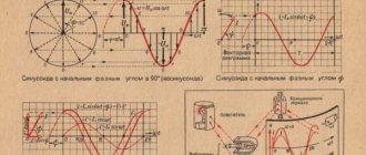
As you know, a capacitor of any capacity has infinite resistance for direct current. But the AC resistance is calculated using this formula:
Rc = 1 / 2πfC
that is, the larger the capacitance C and the higher the current frequency f , the lower the resistance.
The beauty is that in reactance the power is also reactive, that is, it is not real. It seems to be there, but it is as if it is not there. In fact, this power does not do any work, but simply returns back to the power source (outlet). Household meters do not take it into account, so you won’t have to pay for it. Yes, it creates an additional load on the network, but this is unlikely to bother you as an end user much =)
Thus, our do-it-yourself LED power supply circuit from 220V takes the following form:
But! It is in this form that it is better not to use it, since in this circuit the LED is vulnerable to impulse noise.
Turning on or off a powerful inductive load located on the same line as you (air conditioner motor, refrigerator compressor, welding machine, etc.) leads to the appearance of very short voltage surges in the network. Capacitor C1 represents almost zero resistance for them, therefore a powerful impulse will go straight to C2 and VD5.
Unfortunately, electrolytic capacitors, due to their large parasitic inductance, do not cope well with RF interference, so most of the pulse energy will go through the pn junction of the LED.
Another dangerous moment arises if the circuit is turned on at the moment of the voltage antinode in the network (i.e. at the very moment when the voltage in the outlet is at its peak value). Because C1 is completely discharged at this moment, causing too much current to flow through the LED.
All this over time leads to progressive degradation of the crystal and a decrease in the brightness of the glow.
To avoid such sad consequences, the circuit must be supplemented with a small quenching resistor of 47-100 Ohms and a power of 1 W. In addition, resistor R1 will act as a fuse in case of breakdown of capacitor C1.
It turns out that the circuit for connecting an LED to a 220 volt network should be like this:
And there remains one more small nuance: if you unplug this circuit from the socket, then some charge will remain on capacitor C1. The residual voltage will depend on the moment at which the power supply circuit was broken and in some cases may exceed 300 volts.
And since the capacitor has nowhere to discharge except through its internal resistance, the charge can be retained for a very long time (a day or more). And all this time the Conder will be waiting for you or your child, through which it can be properly discharged. Moreover, in order to receive an electric shock, you do not need to go into the depths of the circuit; you just need to touch both contacts of the plug.
To help the condenser get rid of unnecessary charge, we connect any high-resistance resistor (for example, 1 MOhm) in parallel with it. This resistor will not have any effect on the design operating mode of the circuit. It won't even warm up.
Thus, the completed diagram for connecting an LED to a 220V network (taking into account all the nuances and modifications) will look like this:
The capacitance value of capacitor C1 to obtain the required current through the LED can be taken directly from Table 2 , or you can calculate it yourself.
Here you can see how to further improve this circuit by adding a current stabilizer on one transistor and a zener diode. This will significantly reduce ripple and extend the life of the LEDs.
Calculation of a quenching capacitor for an LED
I will not give tedious mathematical calculations, I will immediately give you a ready-made formula for capacity (in Farads):
C = I / (2πf√(U2in - U2LED)) [Ф],
where I is the current through the LED, f is the current frequency (50 Hz), Uin is the effective value of the network voltage (220V), ULED is the voltage on the LED.
If the calculation is carried out for a small number of LEDs connected in series, then the expression √(U2in - U2LED) is approximately equal to Uin, therefore the formula can be simplified:
C ≈ 3183 ⋅ ILED / Uin [uF]
and, since we are doing calculations for Uin = 220 volts, then:
C ≈ 15 ⋅ ILED [µF]
Thus, when the LED is turned on at a voltage of 220 V, for every 100 mA of current, approximately 1.5 μF (1500 nF) of capacitance will be required.
For those who are not good with mathematics, the pre-calculated values can be taken from the table below.
Table 2. Dependence of the current through the LEDs on the capacitance of the ballast capacitor.
| C1 | 15nF | 68 nF | 100 nF | 150 nF | 330nF | 680 nF | 1000 nF |
| ILED | 1 mA | 4.5 mA | 6.7 mA | 10 mA | 22 mA | 45 mA | 67 mA |
Characteristics of capacitors
The capacitor, depending on the state of the electrolyte and the material from which it consists, can be dry, liquid, oxide-semiconductor, oxide-metal. Liquid capacitors are well cooled, these devices can operate under significant loads and have such an important property as self-healing of the dielectric upon breakdown. The dry-type electrical devices under consideration have a fairly simple design, slightly less voltage loss and leakage current. At the moment, dry appliances are the most popular. The main advantages of electrolytic capacitors are their low cost, compact dimensions and high electrical capacity. Oxide analogs are polar (incorrect connection leads to breakdown).
Electrical capacity
When connecting devices for charge condensation, as a rule, the technician is interested in the electrical capacitance that will result.
Electrical capacity shows the ability of a two-terminal network to accumulate charge and is measured in farads. It may seem that the higher this value, the better, but in practice it is not possible to create all possible containers in the world, moreover, this is often not necessary, since all devices used every day use standard condensation devices.
You can connect several devices for condensation in a circuit, creating one condensing container, and the value of the characteristic value will depend on the type of connection, and there are long-known formulas for its calculation.
Design and operating principle
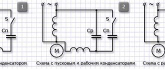
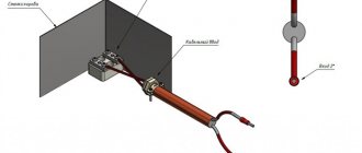
And one more very important point. Calculation of capacitor ratings Legend: Sp - starting, Wed - working. There are several options, but most often electricians install a capacitor in the circuit.
In some designs, a centrifugal switch is installed, which opens the contacts when a certain rotation speed is reached.
Next, knowing the operating voltage and the required capacity, we select capacitors according to the parameters: types and required quantity. Additionally, a phase shift can be obtained by using a starting phase with a higher resistance value and a lower inductance value.
Let's start with the fact that there are two standard schemes for connecting an electric motor to a three-phase network: star and triangle. Active resistors, inductors and capacitors can be used for this.
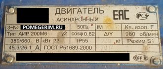
And one end of the starting winding, for one of the workers. Here, each winding is used for its own operating voltage, hence the power.
Determining pairs of wires belonging to one winding The second task, determining the beginning and end of the windings, is somewhat more complicated and requires a battery and a pointer voltmeter. However, in this case the rotation speed will decrease.
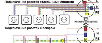
A phase is supplied to one terminal, zero to the other, and the capacitor group is switched on to the third. They even have labels that indicate that you can connect to both a three-phase network and a single-phase network. Connecting a capacitor. How to connect a capacitor to an electric motor. Scheme.