In any technology, LEDs are used to display operating modes. The reasons are obvious - low cost, ultra-low power consumption, high reliability. Since the indicator circuits are very simple, there is no need to purchase factory-made products.
From the abundance of circuits for making a voltage indicator on LEDs with your own hands, you can choose the most optimal option. The indicator can be assembled in a couple of minutes from the most common radioelements.
All such circuits are divided into voltage indicators and current indicators according to their intended purpose.
Working with a 220V network
Let's consider the simplest option - phase checking.
This circuit is a current indicator light found on some screwdrivers. Such a device does not even require external power, since the potential difference between the phase wire and the air or hand is sufficient for the diode to glow.
To display the mains voltage, for example, to check the presence of current in the socket connector, the circuit is even simpler.
The simplest current indicator on 220V LEDs is assembled using capacitance to limit the current of the LED and a diode to protect against reverse half-wave.
Other types of converters
Generally speaking, an amplitude converter is simpler to implement than a full-wave converter - rectification along with integration are also performed on one op-amp.
We add a second op-amp to the rectifier, like a scale amplifier. Choosing this design ensures linear conversion down to millivolts, while at the same time providing the simple and predictable gain control we need to set the conversion scale. The indication of readings can be transferred to any cheapest voltmeter if the gain scale is adjusted accordingly. Another option - a full-wave average rectifier circuit - is more correct when measuring mains voltage. Such a circuit has less dependence of the output value on signal distortion and the presence of interference - the amplitude detector, which we get in the first case, can easily “pump” all sorts of random surges in the mains voltage. The simplest analog circuit we considered above belongs specifically to the full-wave variety, but next we will consider a more advanced version with a unipolar output.
And here we will find that this improved version of the full-wave circuit is less convenient if the gain has to be adjusted “in situ” during the calibration process. In the circuit discussed below (made according to an economical option, also using two op-amps), amplification and rectification are combined and the gain is determined by several resistors connected to each other. You will break your head trying to combine everything and even fit it into standard series of resistances. This problem can be circumvented if you abandon calibration using analog methods and transfer it to digital: the signal from the rectifier is fed to the ADC of the microcontroller (or even Arduino), which controls the display.
Another source of errors is associated with the fact that for the purposes of conversion to digital, the output signal must be smoothed - integrated in one way or another. In the version discussed above, the head itself serves as an excellent integrator due to the mechanical inertia of its rotary system, but here you will have to use circuit engineering methods. Let's consider both of these options separately.
Half-wave (amplitude) converter
A practical circuit of a half-wave transformer sensor signal converter with a scaling amplifier is shown in the figure below. The circuit is assembled using a regular inexpensive dual op-amp LM258. There are no special requirements for the op-amp, with the exception of the power supply range, and, preferably, a fairly high load capacity (we will return to the choice of op-amp later). A Schottky diode is also indicated here as a rectifying diode, but, as we have already said, this is a completely optional choice: any silicon diode with a sufficiently low reverse current (no more than a few microamps) is suitable. 5% resistors with a power of 0.25 W; variable resistor R6 is better in a tuning version (multi-turn “for a screwdriver”). Capacitors C1-C2 are ordinary ceramic. Integrating electrolyte C3 (its nominal voltage does not matter, since our signal is scanty, but just in case it is better to choose it no less than the value of the positive supply voltage + Up) - in theory, of course, tantalum or polymer is better, but this may seem too much expensive, so in a pinch you can get by with regular aluminum. Capacitors C1 and C2 are designed to attenuate power supply noise and should be installed close to pins 4 and 8 of the dual op-amp housing.
At the first op-amp, as you already understood, an amplitude detector is assembled - a half-wave rectifier with a diode in the feedback of the op-amp.
As we have already said, such a connection ensures linearization of the diode characteristics down to several millivolts at the input, provided that its reverse current is sufficiently small (for the specified BAT41 it is no more than 100 nA). Storage capacitor C3 is recharged if the magnitude of the signal at the input exceeds the already accumulated voltage on it, otherwise the diode will remain closed. That is, the voltage on C3 is equal to the amplitude of the input voltage (more precisely, the amplitude of the positive surges of the input voltage). Moreover, in its “pure” form (in the absence of a load), such an amplitude detector does not have a storage capacitor discharge circuit, and the last maximum value of the input voltage will remain on it - theoretically forever. We are not happy with this, so a discharge circuit in the form of resistor R3 was added to the amplitude detector. The time constant of this circuit (about 2 seconds) is chosen to be quite large, but based on the results of practical tests, the capacitance C3 (marked with an asterisk) can be reduced. The smaller the time constant, the shorter the input voltage spikes can be caught, but the more readings bounce due to random reasons and leakage of the 50 Hz frequency to the output. On the second op-amp, a scaling amplifier is assembled according to the standard circuit of a non-inverting op-amp amplifier. In this case, its gain is chosen such as to obtain an output voltage in volts that is numerically equal to the amperes of the current flowing through the conductor being measured. In the formulas shown in the figure, the number 0.084 is the idealized amplitude of the 60 mV AC signal coming from the sensor. Those. we need to get a gain of about 12. In reality, the signal can fluctuate due to the spread of sensors and resistor resistances, the influence of charge circuits (i.e., the output resistance of the op-amp) and discharge, the own resistance of the storage capacitor and its leaks, as well as imperfections of the op-amp on voltage values at the input and output of the amplifier. Therefore, using the tuning resistor R6, the gain can be adjusted from approximately 11 to 15.
The power supply here (as in all other circuits in this article) is necessarily bipolar, and the specific values of the positive and negative voltages completely depend on the desired output swing. The condition “1 V (output) = 1 A (input)” puts us in a fairly strict framework for choosing a power supply and, accordingly, an op-amp model. Thus, the selected LM258 can produce a maximum output voltage that is approximately 2 volts less than the supply, so that with a positive supply of 16 volts, the maximum measured current will be about 14 A (corresponding to a network load power of approximately 3 kW).
Let us remember, however, that only the value + U
n, and, since the power supply of the op-amp does not have to be symmetrical, the value -
U
n can be chosen as the minimum acceptable for the selected type of op-amp. And the limitation on the maximum power supply swing for the op-amp affects the total voltage (from plus to minus), that is, we can significantly increase the positive supply voltage by reducing the negative one. For LM258, the minimum power supply value is about 1.5 V, but for other op-amps with a wide power supply range it can be higher (up to 3-4 volts), therefore, with some reserve, we will take the negative voltage in absolute value equal to 5-6 volts. Thus, for an op-amp with a permissible power supply swing of 30-32 volts, we can set the positive power supply, for example, to 24 volts and, subject to the same condition “1 V (output) = 1 A (input)”, obtain a maximum measured current of 22 amperes, which corresponds to a load of approximately 5 kW. True, you will have to tinker with the design of the power supply for such a circuit, which we will return to later.
And now let us once again turn to the issue of choosing an op-amp, based on the above considerations: you should look at the permissible power supply range (at least 30 volts from plus to minus) and only then at the other characteristics. First of all, we look at the permissible load resistance - it must be at least 1-2 kOhm (the output current is at least approximately 10 mA for each channel of the dual op-amp). Based on these parameters, we chose LM258, at the same time as one of the cheapest in its class (without reservations it can be replaced by LM358, which differs only in the operating temperature range). You can take the classic µA747, it will suit even better (its output stage is more powerful), but for some reason this antique in the “Chip-dip” catalog is priced more expensive. If we move towards more expensive ones, then it makes sense to select an op-amp with a rail-to-rail output property, then the output scale will immediately increase by a couple of volts with the same power supply (for example, OP295 is suitable, costing a couple of hundred rubles and several varieties are even more expensive).
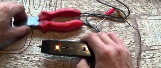
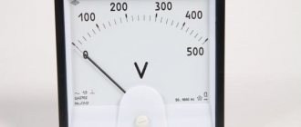
We adjusted the circuit to the condition “1 V (output) = 1 A (input)” so that it could be connected to any DC voltmeter. Including Chinese single boards with LED displays, which can be purchased on Ali for pennies. Choose only those (see photo below) that are powered from a separate source, and not from the signal being measured, and have a scale from zero volts. Please note that these cheap devices will still lie at low input voltages; only branded measuring heads provide any guarantees (see here and here or here), but they are fundamentally more expensive.
As you can see, here we tried to achieve the goal in the cheapest possible way, abandoning the programmable controller and expensive indicator, but burdening ourselves with designing a non-standard power supply. In the next scheme, we will implement a different approach, but there will be no need to invent any frills with food.
Full-Wave Converter (Average Rectifier)
First, let's clarify the problem. In this case, we are going to send the output signal to the ADC of the microcontroller (MK) that controls the indicator. Let this be a banal analog input of Arduino, for which the reference voltage is 5 V. That is. at the output of our circuit we should receive no more than 5 V at the maximum value of the input current. Let’s agree to consider it equal to 27 amperes (approximately 6 kW of power in a 220 V network). In total, provided that for each ampere there is 0.06 volts of the average signal value from the sensor, the gain of the circuit should be about 3 (5/27/0.06).
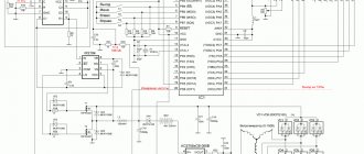
The circuit of an average value rectifier with these parameters is shown in the figure.
For details of the operation of the circuit, I refer you to the monograph by V. S. Gutnikov at the link above. Note that resistors R2, R4 and R5 marked in yellow must be from the series with an accuracy of 1% (graduation E96). Of course, you can simply try to select the required resistance values or compose them from the usual 5-10 percent, but experience shows that this will require much more time and effort than immediately purchasing the required values. If the resistors are not precisely adjusted, then the positive and negative half-cycles of the gain will not coincide, which will give rise to an additional source of errors. For the same purpose, resistor R3 is adjusted so that the input impedance of the amplifier at the second op-amp is approximately the same for positive and negative half-waves. The calculation formulas are shown in the figure; using them, you can select resistors based on the values you have, if you do not get those indicated in the diagram. For our favorite type of op-amp (LM258), you should choose a resistor R2 of at least 2 kOhm (and no more than about 50-100 kOhm), and based on it, calculate the values of the remaining resistors. The choice of op-amp here is much simpler than the previous case - it is enough that it provides the ability to operate from a bipolar power supply of at least ±7 volts (approximately 14-15 volts swing), which corresponds to many more suitable inexpensive types than in the previous case.
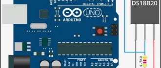
We will not describe the connection to the MK and describe the display controls, since there can be a lot of options, but the task is completely standard and there are countless examples of its implementation. Let us point out only for those who are especially dull that in the data processor with an ADC, you should enter the appropriate scale factor that converts the code units into the current value in amperes (floating point number). If everything is approximately as we assume from the available data, then this coefficient should have a value somewhere in the region of 0.026 (1024/27).
Let us also note that if an ADC is used, the integration can also be converted into digital - even the Arduino ADC is capable of producing about 10 thousand reports per second, which in principle is enough to collect a representative range of instantaneous values of a 50-Hz signal (approximately 200 samples per period). At the same time, we can obtain the true RMS value of the output signal.
DC Voltage Check
Often there is a need to ring the low-voltage circuit of household appliances, or check the integrity of a connection, for example, a wire from headphones.
As a current limiter, you can use a low-power incandescent lamp or a 50-100 Ohm resistor. Depending on the polarity of the connection, the corresponding diode lights up. This option is suitable for circuits up to 12V. For higher voltages, you will need to increase the limiting resistor.
Operating principle of an indicator screwdriver
A voltage indicator that is universal and accessible to all segments of the population should be in the arsenal of every owner. Troubleshooting electrical wiring using reliable, compact devices that identify the voltage in the network eliminates the danger to the health and life of the technician. The design of the indicator screwdriver is simple and has a small number of parts.
The main structural elements of the device, which can show phase and zero, include:
- a housing consisting of an insulated handle, a rod, at the end of which there is a screwdriver blade;
- high resistance resistor;
- indicator light;
- spring;
- contact plate.
The principle of operation of a contact-type indicator screwdriver is based on the passage of electric current through the tip after it touches the phase wire, resistor and light bulb, causing it to glow, as well as its subsequent departure using touch contact towards the ground through the body of the master. High resistor resistance results in low voltage. Its magnitude is imperceptible and safe for human health and life.
Indicator for microcircuits (logic probe)
If there is a need to check the performance of a microcircuit, a simple probe with three stable states will help with this. If there is no signal (open circuit), the diodes do not light up. If there is a logical zero on the contact, a voltage of about 0.5 V appears, which opens transistor T1; if there is a logical one (about 2.4 V), transistor T2 opens.
This selectivity is achieved thanks to the different parameters of the transistors used. For KT315B the opening voltage is 0.4-0.5V, for KT203B it is 1V. If necessary, you can replace the transistors with others with similar parameters.
What is an indicator screwdriver?
This is a tool designed to detect voltage in the electrical network, including hidden ones. Externally, the model may look like a regular flat-head screwdriver with a transparent handle or have a different appearance. However, a probe in the form of a flat bit is required - this is what is used to check the contacts.
Insulation of the handle is also required - the metal part of the device should not come into contact with unprotected human skin, and any metal parts on the handle should not have direct contact with the probe.
Option for car
A simple circuit for indicating the vehicle's on-board voltage and battery charge. The zener diode limits the battery current to 5V to power the logic chip.
Variable resistors allow you to set the voltage level to trigger the LEDs. It is better to carry out the setup from a network stabilized power source.
Please rate the article. We tried our best:)
Did you like the article? Tell us about her! You will help us a lot :)
Wire colors and designations
In order to find the phase, neutral and ground wires of electrical wiring without instruments, they, in accordance with the rules of the Electrical Installation Code, are covered with insulation of different colors.
The photo shows the color marking of the electrical cable for single-phase electrical wiring with an alternating current voltage of 220 V.
This photo shows the color coding of an electrical cable for 380V AC three-phase wiring.
According to the presented diagrams, wires began to be marked in Russia in 2011. In the USSR, the color marking was different, which must be taken into account when searching for phase and zero when connecting installation electrical products to old electrical wiring.
What is the difference between N and PE wires in electrical wiring
According to modern requirements of the PUE, in addition to the phase and neutral wires, a yellow-green ground wire must also be supplied to the apartment.
The neutral N and grounding PE wires are connected to one grounded bus of the panel in the entrance of the house. But they perform different functions. The neutral wire is intended for electrical wiring, and the grounding wire is intended to protect people from electric shock and is connected to the housings of electrical appliances through the third contact of the electrical plug. If an insulation breakdown occurs and a phase gets into the body of an electrical device, then all the current will flow through the grounding wire, the fuse links will burn out or the circuit breaker will trip, and no person will be harmed.
If the electrical wiring is laid indoors with a cable without color marking, it is impossible to determine where the neutral conductor is and where the grounding conductor is, since the resistance between the wires is hundredths of an ohm. The only clue can be the fact that the neutral wire is inserted into the electric meter, and the grounding wire passes by the meter.
Attention! Touching exposed parts of a circuit connected to an electrical outlet may result in electric shock.