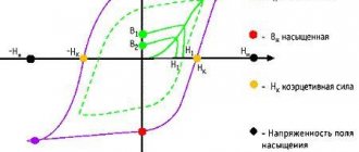
Voltage indicators above 1000 V (UVN) react to the capacitive current that flows through the indicator when its working part is introduced into the electric field created by the live parts of the electrical installation that are energized and the “ground” of the grounded structure of the electrical installation. The voltage indicator must consist of the main parts: working, indicator, insulating, and also have a handle. The voltage indicator used is a protective device when working in electrical installations.
The working part is equipped with elements that react to the presence of voltage on the controlled current-carrying part.
The housing of the working part of the voltage indicator up to 20 kV inclusive must be made of electrical insulating materials with particularly stable dielectric characteristics. The housing of the working part of the voltage indicator 35 kV and above can be made of metal.
The working part of the voltage indicators above 1000 V may contain an electrode tip for direct contact with the current-carrying part being tested and may not contain an electrode tip (non-contact type indicator).
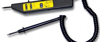
The indicator part of the voltage indicator, which can be combined with the working part, contains elements of light or combined (light and sound) indication. Gas-discharge lamps, LEDs or similar indicators can be used as light indication elements. Sound and light signals must be reliably recognizable. The audio signal should have a frequency of 1-4 kHz and a chopping frequency of 2-4 Hz when indicating phase voltage. The sound signal level must be at least 70 dB at a distance of 1 m along the axis of the sound emitter.
The working part may also contain a body for its own serviceability monitoring. Control can be carried out by pressing a button or be automatic by periodically sending special control signals. At the same time, it is necessary to ensure the possibility of fully checking the serviceability of the electrical circuits of the working and indicator parts.
The working parts should not contain switching elements intended for turning on power or switching ranges.
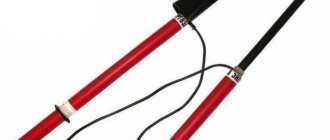
The insulating part of the voltage indicator above 1000 V can be composed of several components. To connect the components together, parts made of metal or insulating material can be used. They allow the use of a telescopic design, but spontaneous folding must be prevented.
The voltage indicator handle can be combined with the insulating part as one whole or as a separate unit.
The design and weight of voltage indicators must ensure that one worker can work with them.
The electrical circuit and design of the voltage indicator must ensure its operability without grounding the working part of the indicator, including when checking the absence of voltage, carried out from telescopic towers or from wooden and reinforced concrete supports of overhead power lines - 6 (10) kV.
The minimum dimensions of the insulating part and the handle of the voltage indicator above 1000 V are given in table. 1.
| Rated voltage of the electrical installation, kV | Length, mm | |
| insulating part | handles | |
| From 1 to 10 | 230 | 110 |
| Above 10 to 20 | 320 | 110 |
| 35 | 510 | 120 |
| 110 | 1400 | 600 |
| Above 110 to 220 | 2500 | 800 |
Table 1. Minimum dimensions of the insulating part and handle of the voltage indicator above 1000 V
The voltage indicator indication voltage is above 1000 V and should be no more than 25% of the rated voltage of the electrical installation.
For voltage indicators without a built-in power supply with a pulse signal, the indication voltage is the voltage at which the signal interruption frequency is at least 0.7 Hz.
For voltage indicators with a built-in power supply with a pulse signal, the indication voltage is the voltage at which the signal interruption frequency is at least 1 Hz.
The remaining UVN indication is the voltage at which there are distinct light and sound signals.
The time of appearance of the first signal when touching a live part under voltage equal to 90% of the rated phase voltage should not exceed 1.5 s.
The working part of the indicator for a certain voltage should not react to the influence of neighboring circuits of the same voltage, spaced from the working part at the distance specified in the table. 2.
| Rated voltage of the electrical installation, kV | Distance from the pointer to the nearest wire of the adjacent circuit, mm |
| Above 1 to 6 | 150 |
| Above 6 to 10 | 220 |
| Above 10 to 35 | 500 |
| 110 | 1500 |
| 150 | 1800 |
| 220 | 2500 |
Table 2. Distance to the nearest wire of an adjacent circuit
Operational tests of voltage indicators above 1000 V
During operation, mechanical tests of voltage indicators are not carried out.
Electrical tests of high voltage indicators consist of testing the insulating part with increased voltage and determining the indication voltage.
Testing of the working part of a voltage indicator up to 35 kV is carried out for indicators of such a design, during operations with which the working part can cause a phase-to-phase fault or a phase-to-ground fault. The need to test the insulation of the working part is determined in accordance with the operating manuals.
High voltage indicators with a built-in power supply monitor their condition and, if necessary, recharge the battery or change the batteries.
When testing the insulation of the working part, voltage is applied between the tip electrode and the screw connector. If the UVN does not have a screw connector electrically connected to the indication element, then the auxiliary electrode for connecting the test installation wire is fixed at the boundary of the working part.
When testing the insulating part, voltage is applied between the element of its fastening with the working part and a temporary electrode placed at the restrictive ring on the side of the insulating part.
The indication voltage of the UVN indicator with a gas-discharge indicator lamp is determined according to the same scheme in which the insulation of the working part was tested.
When determining the indication voltage of other high-voltage indicators that have an electrode tip, it is connected to the high-voltage terminal of the testing installation. When determining the indication voltage of indicators without an electrode-tip, you need to touch the end side of the working part (head) of the UVN to the high-voltage terminal of the test installation.
In both of the latter cases, the auxiliary electrode is not installed on the pointer and the grounding terminal of the test installation is not connected.
UVN type high voltage device
The device on the high voltage side (HVN) is designed to switch on and off the 6, 10 kV power circuit using a load switch and is used to complete transformer substations.
Main technical parameters
| Maximum operating voltage (linear), kV: | 7,2; 12,0 |
| Rated current of primary circuits, A: | 400; 630 |
| Rated operating current, A: | 40; 50; 80; 100; 160; 250; 400; 630 |
| Rated current of busbars, A: | 400; 630 |
| Limit thermal resistance current (short-term current), kA: | 10 |
| Overall dimensions, mm: - width - depth - height | 800 800 1900 |
Symbol structure
UVN is manufactured in the following versions:
- “Blind input” cabinet type BB-1. High-voltage cables are connected directly to the HV terminals of the power transformer. The BB-1 cabinet is mounted directly on the transformer.
- Cabinet with switch VNA-10/630 type UVN-1 (ShVV-1).
- Cabinet with switch VNA-10/630 and fuses type UVN-2 (ShVV-2).
- Cabinet with switch VNR-10/400 type UVN-3 (ShVV-3).
- Cabinet with switch VNR-10/630 and fuses type UVN-4 (ShVV-4).
- Cabinet with switch RVZ-10/630 type UVN-5 (ShVV-5).
- Cabinet with switch RVZ-10/630 and fuses type UVN-6 (ShVV-6).
Design
UVN cabinets are a frame metal structure with a front door, inside which switching and auxiliary equipment is permanently installed. On the side of the door and at the ends of the shield, the degree of protection is IP20; bottom, top and back - IP00 according to GOST 14254. Above the door there is a panel in which lighting fixtures are mounted. The shields of adjacent cameras form a channel for wiring auxiliary circuits.
The cabinet design provides for cable and busbar entry.
Formulation of the order
An order for the production of UVN is issued in the form of a questionnaire.
When ordering, you must indicate: the purpose of the cabinet, the rated current of the main circuits, the rated voltage, the numbers of the main circuit diagrams.
In addition to the basic data, the order should indicate the layout of the cabinets and the number of additional units.
(117 Kb)
Rules for using voltage indicators above 1000 V (UVN)
Before you start working with the pointer, you need to check its serviceability. The serviceability of UVNs that do not have a built-in monitoring device is checked using special devices, which are a small-sized source of increased voltage, or by briefly touching the pointer-electrode to live parts that are energized. The serviceability of the indicator, which has a built-in control unit, is checked in accordance with the operating instructions.
When checking the absence of voltage, the contact time of the working part of the pointer with the current-carrying part being tested must be at least 5 s (in the absence of a signal).
It must be remembered that although some types of voltage indicators can signal the presence of voltage at a distance from the live part, direct contact with the working part of the indicator is a mandatory action.
In electrical installations with voltages above 1000 V, you need to use dielectric gloves to use the voltage indicator.
ELECTROlaboratory
Good day, dear friends.
Our conversation today is about high voltage indicators (HVI). I’ll immediately make a reservation that the article will consider UVNs for installations up to 10 kV.
Since I am a member of the company’s commission for testing knowledge on electrical safety, during the exam I often ask newly hired electricians a question
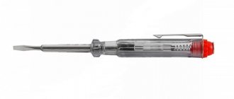
- What is this and I hand them the assembled UVN:
Only one out of five answers my question. This is such a sad statistic.
Purpose of UVN.
Voltage indicators are designed to determine the presence or absence of voltage on live parts of electrical installations. UVN is one of the main protective equipment.
General technical requirements for voltage indicators are set out in the state standard GOST 20493 Voltage indicators. General technical conditions.
Operating principle and design of UVN
Voltage indicators above 1000 V react to capacitive current flowing through the indicator when its working part is introduced into the electric field formed by live parts of electrical installations that are energized, and the “ground” and grounded structures of electrical installations.
The indicators must contain the main parts: working, indicator, insulating, and also a handle.
The working part contains elements that react to the presence of voltage on the controlled current-carrying parts.
The housings of the working parts of voltage indicators up to 20 kV inclusive must be made of electrical insulating materials with stable dielectric characteristics. The housings of the working parts of voltage indicators of 35 kV and above can be made of metal.
The working part may contain an electrode tip for direct contact with the controlled current-carrying parts and not contain an electrode tip (non-contact type indicators).
The indicator part, which can be combined with the working part, contains elements of light or combined (light and sound) indication. Gas-discharge lamps, LEDs or other indicators can be used as light indication elements. Light and sound signals must be reliably recognizable. The audio signal should have a frequency of 1-4 kHz and a chopping frequency of 2-4 Hz when indicating phase voltage. The sound signal level must be at least 70 dB at a distance of 1 m along the axis of the sound emitter.
The working part may also contain a body for its own serviceability monitoring. Control can be carried out by pressing a button or be automatic by periodically sending special control signals. In this case, it must be possible to fully check the serviceability of the electrical circuits of the working and indicator parts.
Working parts must not contain switching elements intended for turning on power or switching ranges.
The insulating part of the signs must be made of electrical insulating materials that do not absorb moisture, with stable dielectric and mechanical properties.
The surfaces of the insulating parts must be smooth, without cracks, delaminations or scratches.
The use of paper-bakelite tubes for the manufacture of insulating parts is not allowed.
The insulating part can be composed of several links. To connect the links to each other, parts made of metal or insulating material can be used. It is permissible to use a telescopic design, but spontaneous folding must be prevented.
The handle can be one piece with the insulating part or be a separate link.
The design and weight of the signs must ensure that one person can operate them.
The electrical circuit and design of the indicator must ensure its operability without grounding the working part of the indicator, including when checking the absence of voltage carried out from telescopic towers or from wooden and reinforced concrete supports of 6-10 kV overhead lines.
The minimum dimensions of insulating parts and handles for voltage indicators above 1000 V are given in the table
The voltage indicator indication voltage should be no more than 25% of the rated voltage of the electrical installation.
For indicators without a built-in power supply with a pulse signal, the indication voltage is the voltage at which the signal interruption frequency is at least 0.7 Hz.
For indicators with a built-in power supply with a pulse signal, the indication voltage is the voltage at which the signal interruption frequency is at least 1 Hz.
For other indicators, the indication voltage is the voltage at which there are distinct light (light and sound) signals.
The time for the first signal to appear after touching a live part under voltage equal to 90% of the rated phase voltage should not exceed 1.5 s.
The working part of the indicator for a certain voltage should not respond to the influence of neighboring circuits of the same voltage, spaced from the working part at the distances indicated in the table:
Performance tests.
The tests of UVN were discussed in the article “Protective means. Electrical testing”
Terms of use
Before you start working with the pointer, you need to check its serviceability.
The serviceability of indicators that do not have a built-in monitoring device is checked using special devices, which are small-sized sources of increased voltage, or by briefly touching the electrode-tip of the indicator to live parts that are known to be energized.
The serviceability of indicators with a built-in control unit is checked in accordance with the operating manuals.
When checking the absence of voltage, the time of direct contact of the working part of the indicator with the controlled current-carrying part must be at least 5 s (in the absence of a signal).
It should be remembered that although some types of voltage indicators can signal the presence of voltage at a distance from live parts, direct contact with them by the working part of the indicator is mandatory.
In electrical installations with voltages above 1000 V, the voltage indicator should be used with dielectric gloves.
In conclusion, I note that before using the UVN, pay attention to the stamp that must be pasted in the area of the handle, which will indicate the voltage of the electrical installations in which this UVN is allowed to be used and the date for the next check (test) of the UVN. REMEMBER!!! to use protective equipment that has expired .
That's all for me today.
I wish you success.