The controller is made in a SOP-8 housing, has a metal heat sink on the bottom surface that is not connected to contacts, and allows you to charge the battery with a current of up to 1000 mA (depending on the current-setting resistor). Requires a minimum of attachments. In fact, TP4056 is a more sophisticated modification of the TP4054 chip.
TP4056 automatically completes the charging cycle when its voltage reaches 4.2V and the charging current decreases to 1/10 of the programmed value. The module has an indication of the charging process. At the moment of charging, the red LED lights up, and when the battery is fully charged, the green LED lights up, while the red one goes out.
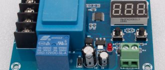
In addition to the TP4056 charging controller, two chips DW01 (protection circuit) and ML8205A (double MOSFET switch) are added to the board; they are used to protect the battery from overdischarge, overcharge, overload and short circuit.
The TP4056 module is ideal for portable devices. If an Arduino project requires full charging of Li-ion batteries with the ability to connect a load and with combustion protection, then this charge board will completely cope with this task.
- 1 TP4056 Specifications
- 2 Description of module pins
- 3 Schematic diagram of the module on TP4056
- 4 Connection diagram TP4056
- 5 Charging process
- 6 Charging current setting
- 7 Materials
- 8 Buy TP4056 on AliExpress
- 9 Similar posts
How to charge lithium batteries
The whole trick of charging lithium batteries lies in the fact that neither the charge current nor the voltage should be constant. The charging process must take place in certain phases:
- When the battery is completely discharged (< 3 volts), the charging current should be maximum. Typically it should not exceed the battery capacity (C).
- As the charge accumulates, i.e. As the battery voltage increases, the charging current should decrease.
- When reaching 90% of the full charge, the charge current should drop to a level of about 0.1C. As soon as the battery voltage reaches 4.1-4.15 V, the charging process should stop.
Following these rules for charging a lithium battery will ensure it has a long service life. Discharging a lithium battery below 3 volts, as well as regularly recharging it even by 0.1 volts, significantly reduces the battery capacity.
Marking of lithium batteries 18650
There are markings on the surface of the battery case. Here you can find complete information about the technical properties. In addition to the manufacturing date, expiration date and manufacturer's brand, the device of 18650 lithium batteries and the consumer qualities associated with this aspect are encrypted.
- ICR – lithium-cobalt cathode. The battery has a high capacity, but is designed for low current consumption. Used in laptops, video cameras and similar long-lasting equipment with low energy consumption.
- IMR – lithium manganese cathode. It has the ability to produce high currents and can withstand discharge up to 2.5 a/h.
- INR – nickelate cathode. Provides high currents, withstands discharge up to 2.5 V.
- NCR is a specific marking of Panasonic. The properties of the battery are identical to the IMR. Nickelates, cobalt salts, and aluminum oxide are used.
Positions 2,3,4 are called “high-current”, they are used for flashlights, binoculars, and cameras.
Lithium ferrophosphate batteries have the ability to operate at deep minus temperatures and are restored during deep discharge. Undervalued on the market.
By the marking you can determine whether this is a rechargeable lithium battery with the letters I R. If there are letters C/M/F, the cathode material is known. The capacity indicated will be mA/h. The release date and expiration date are located in different places.
You should know that manufacturers of rechargeable lithium batteries do not have products with a capacity of more than 3,600 mAh. In order to repair a laptop battery or assemble a new one, you need to purchase batteries without protection. To use a single copy, you need to buy elements with protection.
Lithium battery charge control chips
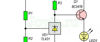
Today there are microcircuits that are a ready-made charge controller for lithium batteries. One of such microcircuits is TP4056 (). The circuit diagram of the lithium battery charge controller on the TP4056 is as follows:
However, if you decided to implement it, then I hasten to disappoint you. The effort, time and money spent will be many times greater than the cost of a finished module built according to exactly the same circuit and even enhanced with more powerful output transistors.
Schematic diagram of the module on TP4056
The circuit (without protection) is almost identical to the circuit from the datasheet, with the exception of connecting the battery temperature sensor. If necessary, you can remove the temperature sensor input with a separate wire by soldering it to the tab and cutting it off from GND. Or by lifting the paw above the board and soldering it.
The protection circuit based on DW01A (from the specification) is as follows:
Below is a typical connection of TP4056, protection based on DW01A and S-8205A mosfets.
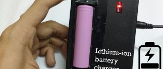
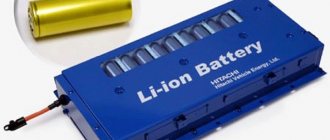
Li-ion battery charge control module
A ready-made lithium battery charge control module can be purchased for only 30 cents .
Please note that such modules are not only available with a battery charge controller. There are also versions with battery discharge monitoring.
The picture shows all four variants of such modules. The two left modules are completely similar to the two right modules, the only difference is the installed connector. But among themselves, the two left modules, like the two right ones, differ in the ability to control battery discharge.
If the module, in addition to the contacts for the battery B+ and B-, also contains contacts OUT+ and OUT- , this means that the module is able to control the discharge of the battery, and the load is connected to the battery through the module.
Don't be afraid that the version with a discharge controller will drain your battery. Measurements have shown that the current consumption of the module itself is only about 5 micro Amperes. Which even surprised me a little.
***
Now you know what the battery controller is in a mobile device and you can figure out whether one of its functions is causing the problem. For example, it could be overheating , or a faulty power adapter with too high a voltage value.
Find out more about the problems
Want to add something important about controllers? Leave information or questions in the comments. We are waiting for your messages on VKontakte @NeovoltRu.
Subscribe in the group to news from the world of gadgets, learn about improving their autonomy and progress in scientific research on batteries. Connect with us on Facebook and Twitter. We also maintain a busy blog on Zen and Medium - come check it out.
Module performance measurement
We will measure the following:
- Charging process - let's see how the charging current changes depending on the voltage on the battery.
- Discharge , or rather the ability of the module to continuously supply current to the load, as well as the ability to cut off the battery upon reaching the discharge threshold.
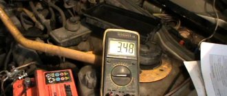
For these purposes we need a voltmeter and an ammeter. But I’m a lazy person, and measuring by hand in our age is a monkey’s work. Therefore, the PIC18F4550 microcontroller was called to help. It can communicate with a computer via USB and has a 10-bit ADC on board.
The ammeter and voltmeter are shown below conventionally. Both the voltmeter and the ammeter are implemented using differential amplifiers . To measure current, a low-resistance resistor is used, the voltage difference from the terminals of which is measured by a differential amplifier. A separate article was recently devoted to this method of measuring current .
From the differential outputs Amplifiers send the signal to the ADC of the microcontroller. The ADC voltage step is about 5 mV, which is more than enough for such measurements. To reduce the error as much as possible, the data arriving over 10 seconds was averaged (200 incoming values each).
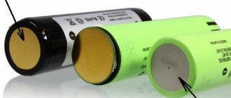
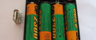
All torture was carried out using a Sony VTC6 18650 battery. This battery has a capacity of 3000 mAh. The maximum output current of the battery can reach 30A.
Operating modes of lithium batteries
There are 2 main modes of using lithium batteries:
- Buffer – for example, in modern uninterruptible power supplies. In this case, the battery is constantly fed from the mains, and during power outages, it releases the accumulated charge to the equipment connected to it. When the power supply from the network is restored, the battery is recharged again and is in constant readiness for further use.
- Cyclic - implies an alternation of charge-discharge phases, when after the passive phase of charge recovery there is a long phase of active operation. In this mode, batteries for electric bicycles and other types of personal electric transport, forklifts, floor scrubbers, electric vehicles, motor boats, mobile coffee machines and other equipment operate. The service life of such batteries is measured not in years, but in the number of deep discharge cycles (up to 80%) and subsequent charge.
Lithium-ion batteries are successfully used in both buffer and cyclic mode. If the operation of the battery involves harsh conditions and frequent deep discharges, lithium iron phosphate batteries (LiFePO4) cope best with such tasks. In particular, they are used to power boat electric motors, warehouse and cleaning equipment, e-bikes and other types of electric vehicles.
Battery charge measurements
To study the battery charging process, the following measuring circuit was implemented:
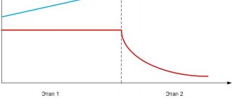
The graph obtained with its help is presented in the following picture. For convenience in blue , and in red . In this case, the time is indicated in seconds.
6000 seconds correspond to 100 minutes, or in a more familiar form it is 1 hour 40 minutes. Accordingly, fully charging the battery took about 6 hours. With a battery capacity of 3000 mAh, the average charge current can be considered equal to 500 mA.
The graph clearly shows all three charging phases described above. The circuit works as expected. There is a small variation in the final voltage between different instances of modules, but it is not critical.
It is worth noting that any measurement of a physical quantity is only an attempt to approximate the true value. You should not pay attention to small teeth; their nature can be caused by both the unevenness of the ADC and the nonlinearity of the module. Which is not at all critical.
In any case, the resulting dependence perfectly satisfies all the rules of battery charging.
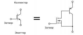
What does the battery controller consist of?
The electrical circuit is very simple and does not require deep knowledge of circuit design. Although manufacturers of expensive smartphones are trying to improve it, the design principle remains the same for everyone.
On the printed circuit board of the battery controller in most cases the following are placed:
- • resistor in the power circuit,
- • storage capacitor,
- • the protection controller itself in the form of a microcircuit,
- • resistor in the protection circuit,
- • thermistor,
- • MOSFET transistors.
In some cases, the controller is wired into three contacts instead of two - then, in addition to the traditional “plus” and “minus”, the manufacturer uses the so-called “information contact”.
Smart module saves battery
It’s not for nothing that I called this module smart. If you look closely at the moment power is supplied to the module, you can see a small step in the current dependence. This is what it looks like close up:
We are talking about a step between 500 and 600 seconds at the 100 mA level. This step is present if the battery is discharged below 3 volts.
The module is careful with the battery. First, he brings the voltage on the battery to approximately 3 volts with a current of 100 mA. And only then it begins to fire through the 1 ampere battery. Well, or the current that was set by the resistor RPROG .
Description of module pins
| Conclusion | Description |
| IN+ | Vcc/Power |
| IN- | GND / Common |
| OUT+ | Load "+" |
| OUT- | Load "-" |
| BAT+ | To the "+" of the battery |
| BAT- | To "-" battery |
Battery discharge monitoring
To study the output characteristics of the module, the circuit was slightly modified. A variable resistor was installed as a load, connected in series with an ammeter to the output contacts of the module.
The load resistor was set so that the initial discharge current was about 1.15 A. the load was constant, and accordingly the current in the output circuit dropped with a drop in battery voltage.
As can be seen from the graph, the module successfully cut off the load from the battery in the region of 5000 seconds. This means that the module supplied a current of about 1 ampere for an hour and a half and did not bend. Excellent result)
The increase in battery voltage after disconnecting the load is caused by chemical recovery of the battery after delivering a decent current for such a long time.
If the battery was completely discharged and the module turned it off, it will turn on when the charger is connected, as soon as the voltage on the battery reaches a level of 2.9 - 3 volts.
Operating principle of the board
The largest electronics manufacturers are engaged in the production of charging controllers: Panasonic, Samsung, Sony, LG, ATL, HYB, Sanio. They distribute the circuits to other manufacturers, who pass them off as their own products.
The operating principle of the microcontroller is to ensure normal operating conditions for the battery, in accordance with its basic technical characteristics:
Operating principle of the controller.
- maximum voltage – 4.2V (the board protects against minor overcharging, which has a detrimental effect on the overall service life);
- minimum voltage – 2.75V (if the charge level of the 18650 battery drops below 2V, it will be irrevocably damaged);
- minimum temperature - charging and using the battery at 20°C and below is not allowed (the battery can suddenly lose capacity, go into overdischarge, and as a result its consumer properties will significantly deteriorate);
- maximum temperature - operation and storage of Li-Ion batteries at temperatures above +40 is prohibited (lithium-ion batteries are exposed to high temperatures and may smoke, ignite, or explode);
- charging speed - the timing is affected by the current strength and battery capacity. The maximum capacity of a reusable battery marked 18650 is 3600 mAh. That is, by charging 1A you can replenish the charge in 1 hour, 2A current - 30 minutes, 15A current - 4 minutes.
The marking of a 18650 lithium-ion battery means its dimensions - that is, the length of the battery is 65 mm, the diameter is 18 mm.
How the module heats up
During charging, when the current is 1 ampere, the module gets quite hot. It is worth considering this fact when using the module in a closed device. Thus, in the open air, the temperature of the module reached values of more than 70 degrees ( according to the thermocouple ).
If the module is installed in a closed case, it is advisable to reduce the maximum charge current to 500-700 mA. But you still shouldn’t attach it to thermal glue.
The module itself has overheating protection. So, when the module overheats, it begins to limit the output current. So he most likely will not die from overheating. But you shouldn’t rely entirely on protection))
Setting the charging current
The controller has a good CC/CV profile and can be adapted to many different charging configurations and Li-ion battery types. The rated charging current can be changed by selecting the resistor Rprog (default: 1A).
| Resistor (kOhm) | Charge current (mA) |
| 30 | 50 |
| 20 | 70 |
| 10 | 130 |
| 5 | 250 |
| 4 | 300 |
| 3 | 400 |
| 2 | 580 |
| 1.66 | 690 |
| 1.5 | 780 |
| 1.33 | 900 |
| 1.2 | 1000 |
Where to buy a Li battery charging module?
I cannot vouch for all such modules. Every self-respecting resident of the Middle Kingdom does not disdain their production. The modules shown were ordered not for the first time from a specific seller. Which I recommend to you too.
It is not profitable to buy such modules individually - sellers begin to increase the price both for the module and for delivery. It’s more convenient and cheaper to purchase 5 or 10 pieces at a time, even if you need 1-2. It is very convenient when you have a bunch of such modules somewhere in the closet and, if necessary, you can quickly figure out how to charge them. Here are links to different lots from a verified store:
- 5 pieces. micro-USB – 1.57$
- 5 pieces. mini-USB – 1.57$
- 10 pieces. micro-USB – 2.61$
- 10 pieces. mini-USB – 2.61$
$1.57 for 5 pieces, and even more so $2.61 for 10 pieces—that’s a pittance. Many radio parts stores will ask you for a similar amount for each such module.
prices from September 16, 2020
Yes, the links are referral, but by purchasing through them you lose absolutely nothing (and now they don’t even give you cashback). But with this you are telling me thank you for the work done and helping my project with a pretty penny. Thank you for this too.
TP4056 Specifications
- Controller used : TP4056 and DW01 to protect the battery from overdischarge and overcharge;
- Charging mode : linear 1%;
- Charging current : up to 1A (configurable);
- Charging Accuracy: 1.5%;
- Input voltage : 4.5 - 5.5V;
- Full charge voltage : 4.2V;
- Indicators : red - charging, green (blue in some versions) - charge complete;
- Input connector : mini USB, MicroUSB or contacts for soldering wires;
- Temperature range : -10 to +85 degrees C;
- Reverse polarity protection : no;
- Overcharge protection : 4.30±0.050 V ;
- Overdischarge protection : 2.40±0.100 V;
- Weight : 5 g;
- Board dimensions : 25 × 17 × 4 mm.