What is the capacitance of a capacitor measured in?
One of the most important characteristics of a capacitor is its capacity. This parameter is determined by the amount of electricity accumulated by this device. The accumulation occurs in the form of electrons. The number of them placed in the capacitor determines the capacitance value of a particular device.
The unit used to measure capacitance is the farad. A capacitor's capacity of 1 farad corresponds to an electric charge of 1 coulomb, and the potential difference across the plates is 1 volt. This classical formulation is not suitable for practical calculations, since the capacitor collects not charges, but electrons. The capacity of any capacitor is directly dependent on the volume of electrons that can accumulate during normal operating conditions.
The farad is still used to denote capacitance, and the quantitative parameters are determined by the formula: C = Q / U, where C means capacitance, Q is charge in coulombs, and U is voltage. Thus, the mutual relationship between charge and voltage is visible, influencing the capacitor’s ability to accumulate and retain a certain amount of electricity.
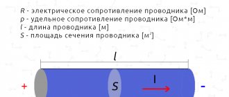
To calculate the capacitance of a parallel-plate capacitor, the formula is used: in which ε = 8.854187817 x 10⁻¹² f/m is a constant value. Other quantities: ε is the dielectric constant of the dielectric located between the plates, S is the area of the plate, and d is the gap between the plates.
Device energy
It is impossible to charge a capacitor instantly. This process requires some time. This phenomenon is used in radio engineering. So, with the help of a capacitor, pulse bursts are smoothed out. To a first approximation, a capacitor is similar to a battery. But at the same time, it differs from it in the principle of energy storage , capacity and charge-discharge rate. When a power source is connected to the terminals of the device plates, the capacitor accumulates charge on them.~
The operation of the device can be explained by analogy with the flow of water. Let there be a vessel with a liquid with a cross-sectional area S. In fact, this is the equivalent of a container. Then the water will be a charge, and the height of the water column will be a voltage. It turns out that energy is the product of charges and height. But if a battery can be imagined as a vessel in which there is a thin hose (lead) and through which water flows (charge), then in a capacitor its tube diameter will be equal to the size of the entire jar. That is, the device can instantly release all the accumulated charge.
When voltage is applied to the plates, the dielectric becomes electrified. As a result, a displacement occurs and energy is transferred to the plates. On one of them there will be an excess of electrons, and it will be conditionally charged negatively, and on the second there will be a deficiency - the conductor will become positive. Therefore, in the formula that determines the charge on the capacitor plates, the dielectric constant of a non-conducting substance is of great importance.
Force arises between the plates. The magnitude acting from the first side is equal to F = ε1 * q, and from the second side F = ε2 * q. Thus, we can write: F = ε1 * q = ε2 * q = E / 2 * q. When the distance between the plates increases from zero to d, the work will be performed: A = F * d. It is aimed at overcoming the interaction force between charged conductors.
That is: A = E / 2 * q * d. Based on the fact that ε = U/d it will be correct to write: A = 1 / 2 q * U. This means that the mechanical work A in accordance with the law of conservation of energy will be equal to the number of charges stored in the electric field of the capacitor: We = C * U2 / 2.
It should be noted that when an alternating signal is applied inside the dielectric, the charge signs constantly change. As a result, heating occurs, which causes the capacitor to fail. This phenomenon is characterized by the dielectric loss tangent. It is defined as the ratio of expended power to reactive power.
Capacitor Energy Formula
Closely related to capacitance is another quantity known as the energy of a charged capacitor. After charging any capacitor, a certain amount of energy is formed in it, which is subsequently released during the discharge process. The capacitor plates interact with this potential energy. They form opposite charges that attract each other.
Tips and warnings
- After the discharge process is completed, you can wrap its terminals with foil so that this radio component remains discharged.
- All capacitors can eventually discharge on their own after a few days, provided they are not connected to external power sources. But it is always better to assume that they are in a charged state and a test discharge will not be superfluous.
- It is necessary to constantly remember that large radio components that switch electrical power are very dangerous. Working with such radio components requires professional skills.
- Always take safety precautions when working with electrical devices.
Capacitor charge formula
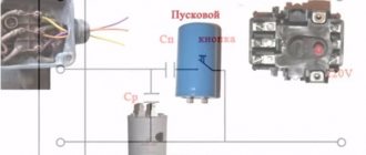
To perform charging, the capacitor must be connected to a DC circuit. A generator can be used for this purpose. Every generator has internal resistance. When the circuit is closed, the capacitor is charged. A voltage appears between its plates equal to the electromotive force of the generator: Uc = E.
The plate connected to the positive pole of the generator is charged positively (+q), and the other plate receives an equal charge with a negative value (-q). The amount of charge q is directly proportional to the capacitance of the capacitor C and the voltage on the plates Uc. This dependence is expressed by the formula: q = C x Uc.
During the charging process, one of the capacitor plates gains and the other loses a certain number of electrons. They are transferred through an external circuit under the influence of the electromotive force of the generator. This movement is an electric current, also known as charging capacitive current (Icharge).
Electronics for everyone
If you connect a resistor and a capacitor, you get perhaps one of the most useful and versatile circuits.
Today I decided to talk about the many ways to use it. But first, about each element separately:
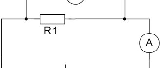
The resistor's job is to limit the current. This is a static element whose resistance does not change; we are not talking about thermal errors now - they are not too large. The current through the resistor is determined by Ohm's law - I=U/R
, where U is the voltage at the resistor terminals, R is its resistance.
The capacitor is a more interesting thing. It has an interesting property - when it is discharged, it behaves almost like a short circuit - the current flows through it without restrictions, rushing to infinity. And the voltage on it tends to zero. When it is charged, it becomes like a break and the current stops flowing through it, and the voltage across it becomes equal to the charging source. It turns out an interesting relationship - there is current, no voltage, there is voltage - no current.
To visualize this process, imagine a balloon... um... a balloon that is filled with water. The flow of water is a current. Water pressure on elastic walls is the equivalent of stress. Now look, when the ball is empty - water flows freely, there is a large current, but there is almost no pressure yet - the voltage is low. Then, when the ball is filled and begins to resist pressure, due to the elasticity of the walls, the flow rate will slow down, and then stop altogether - the forces are equal, the capacitor is charged. There is tension on the stretched walls, but no current!
Now, if you remove or reduce the external pressure, remove the power source, then the water will flow back under the influence of elasticity. Also, the current from the capacitor will flow back if the circuit is closed and the source voltage is lower than the voltage in the capacitor.
Capacitor capacity. What is this? Theoretically, a charge of infinite size can be pumped into any ideal capacitor. It’s just that our ball will stretch more and the walls will create more pressure, infinitely more pressure. What then about Farads, what is written on the side of the capacitor as an indicator of capacitance? And this is just the dependence of voltage on charge (q = CU). For a small capacitor, the voltage increase from charging will be higher.
Imagine two glasses with infinitely high walls. One is narrow, like a test tube, the other is wide, like a basin. The water level in them is tension. The bottom area is the container. Both can be filled with the same liter of water - equal charge. But in a test tube the level will jump by several meters, and in a basin it will splash at the very bottom. Also in capacitors with small and large capacitance. You can fill it as much as you like, but the voltage will be different.
Plus, in real life, capacitors have a breakdown voltage, after which it ceases to be a capacitor, but turns into a usable conductor 
How quickly does a capacitor charge?
Under ideal conditions, when we have an infinitely powerful voltage source with zero internal resistance, ideal superconducting wires and an absolutely flawless capacitor, this process will occur instantly, with time equal to 0, as well as the discharge.
But in reality, there is always resistance, explicit - like a banal resistor, or implicit, such as the resistance of wires or the internal resistance of a voltage source. In this case, the charging rate of the capacitor will depend on the resistance in the circuit and the capacitance of the capacitor, and the charge itself will follow an exponential law
.
And this law has a couple of characteristic quantities:
- T is the time constant
, this is the time at which the value reaches 63% of its maximum. 63% didn’t come about here by chance, it’s directly tied to this formula VALUET=max—1/e*max. - 3T - and at three times the constant the value will reach 95% of its maximum.
Time constant for RC circuit T=R*C
.
The lower the resistance and lower the capacitance, the faster the capacitor charges. If the resistance is zero, then the charging time is zero.
Let's calculate how long it will take for a 1uF capacitor to be charged to 95% through a 1kOhm resistor:
T= C*R = 10-6 * 103 = 0.001s 3T = 0.003s After this time, the voltage on the capacitor will reach 95% of the source voltage.
The discharge will follow the same law, only upside down. Those. after T time, only 100% - 63% = 37% of the original voltage remains on the capacitor, and after 3T even less - a measly 5%.
Well, everything is clear with the supply and release of voltage. What if the voltage was applied, and then raised further in steps, and then discharged in steps as well? The situation here will practically not change - the voltage has risen, the capacitor has been charged to it according to the same law, with the same time constant - after a time of 3T its voltage will be 95% of the new maximum. It dropped a little - it was recharged and after 3T the voltage on it will be 5% higher than the new minimum. What am I telling you, it’s better to show it. Here in multisim I created a clever step signal generator and fed it to the integrating RC chain:
You see how it wobbles. Please note that both charge and discharge, regardless of the height of the step, are always of the same duration!!!
To what value can a capacitor be charged? In theory, ad infinitum, a sort of ball with endlessly stretching walls. In reality, sooner or later the ball will burst, and the capacitor will break through and short-circuit. That's why all capacitors have an important parameter - the maximum voltage
. On electrolytes it is often written on the side, but on ceramic ones it must be looked up in reference books. But there it is usually from 50 volts. In general, when choosing a condenser, you need to ensure that its maximum voltage is not lower than that in the circuit. I will add that when calculating a capacitor for alternating voltage, you should choose a maximum voltage 1.4 times higher. Because on alternating voltage the effective value is indicated, and the instantaneous value at its maximum exceeds it by 1.4 times.
What follows from the above? And the fact is that if a constant voltage is applied to the capacitor, it will simply charge and that’s it. This is where the fun ends.
What if you submit a variable? It is obvious that it will either charge or discharge, and current will flow back and forth in the circuit. Movement! There is current!
It turns out that, despite the physical break in the circuit between the plates, alternating current easily flows through the capacitor, but direct current flows weakly.
What does this give us? And the fact that a capacitor can serve as a kind of separator to separate alternating and direct current into the corresponding components.
Any time-varying signal can be represented as the sum of two components - variable and constant.
For example, a classical sinusoid has only a variable part, and the constant is zero. With direct current it is the opposite. What if we have a shifted sinusoid? Or constant with interference?
The AC and DC components of the signal are easily separated! A little higher, I showed you how a capacitor is charged and discharged when the voltage changes. So the variable component will pass through the conder with a bang, because only it forces the capacitor to actively change its charge. The constant will remain as it was and will be stuck on the capacitor.
But in order for the capacitor to effectively separate the variable component from the constant, the frequency of the variable component must be no lower than 1/T
Two types of RC chain activation are possible: Integrating and differentiating
. They are also a low-pass filter and a high-pass filter.
The low-pass filter passes the constant component without changes (since its frequency is zero, there is nowhere lower) and suppresses everything higher than 1/T. The direct component passes directly, and the alternating component is quenched to ground through a capacitor. Such a filter is also called an integrating chain because the output signal is, as it were, integrated. Do you remember what an integral is? Area under the curve! This is where it comes out.
How is the constant component calculated here? And you can’t tell by looking at it, but we must remember that any periodically signal is expanded into a Fourier series
, turning into the sum of a constant component and a pack of sinusoids of different frequencies and amplitudes.
The high pass filter works in reverse. It does not let in the constant component (because its frequency is too low - 0) - after all, the capacitor for it is equivalent to a break, but the variable gets through the condenser without problems.
And it is called a differentiating circuit because at the output we get the differential of the input function, which is nothing more than the rate of change of this function.
- In section 1, the capacitor is charged, which means current flows through it and there will be a voltage drop across the resistor.
- In section 2, there is a sharp increase in the charging speed, which means the current will sharply increase, followed by a voltage drop across the resistor.
- In section 3, the capacitor simply holds the existing potential. No current flows through it, which means the voltage across the resistor is also zero.
- Well, in the 4th section the capacitor began to discharge, because... the input signal has become lower than its voltage. The current has gone in the opposite direction and there is already a negative voltage drop across the resistor.
And if we apply a rectangular pulse to the input, with very steep edges, and make the capacitance of the capacitor smaller, we will see needles like these:
At the top there is an oscillogram of what is at the input, below is what is at the output of the differential circuit. As you can see, there are powerful surges at the fronts. This is understandable, in this place the function changes sharply, which means the derivative (rate of change) of this function is large, in flat areas the signal is constant and its derivative, the rate of change, is equal to zero - zero on the graph.
And if you drive a saw into the differentiator, the output will be...
rectangle. Well, what? That's right - the derivative of a linear function is a constant, the slope of this function determines the sign of the constant.
In short, if you are currently taking a math course, then you can forget about the godless Mathcad, disgusting Maple, throw the matrix heresy of Matlab out of your head and, taking out a handful of analog loose stuff from your stash, solder yourself a truly TRUE analog computer. The teacher will be shocked
True, integrators and differentiators are usually not made using resistors alone; operational amplifiers are used here. You can google for these things for now, interesting thing
And here I fed a regular rectangular signal to two high- and low-pass filters. And the outputs from them to the oscilloscope:
And this is what happened on the oscilloscope:
Here's a slightly larger section:
>
As you can see, on one the constant component was cut off, on the other the variable.
Okay, we're getting off topic.
How else can you use an RC circuit?
Yes there are many ways. It is often used not only as filters, but also as pulse shapers. For example, when resetting the AVR controller, if you want the MK to start not immediately after turning on the power, but with some delay:
When starting, the condenser is discharged, the current through it is full, and the voltage on it is negligible - there is a reset signal at the RESET input. But soon the capacitor will charge and after time T its voltage will already be at the level of logical one and the reset signal will no longer be sent to RESET - the MK will start. And for AT89C51
it is necessary to organize exactly the opposite of RESET - first submit a one, and then a zero. Here the situation is the opposite - while the condenser is not charged, then a large current flows through it, Uc - the voltage drop across it is tiny Uc = 0. This means that RESET is supplied with a voltage slightly less than the supply voltage Usupply-Uc=Upsupply. But when the condenser is charged and the voltage on it reaches the supply voltage (Upit = Uc), then at the RESET pin there will already be Upit-Uc = 0
Analog measurements
But never mind the reset chains, where it’s more fun to use the RC circuit’s ability to measure analog values with microcontrollers that don’t have ADCs. This uses the fact that the voltage on the capacitor grows strictly according to the same law - exponential. Depending on the conductor, resistor and supply voltage. This means that it can be used as a reference voltage with previously known parameters.
It works simply, we apply voltage from the capacitor to an analog comparator, and connect the measured voltage to the second input of the comparator. And when we want to measure the voltage, we simply first pull the pin down to discharge the capacitor. Then we return it to Hi-Z mode, reset it and start the timer. And then the condenser begins to charge through the resistor and as soon as the comparator reports that the voltage from the RC has caught up with the measured one, we stop the timer.
Knowing according to which law the reference voltage of the RC circuit increases over time, and also knowing how long the timer has been ticking, we can quite accurately find out what the measured voltage was equal to at the time the comparator was triggered. Moreover, it is not necessary to count exponents here. At the initial stage of charging the condenser, we can assume that the dependence there is linear. Or, if you want greater accuracy, approximate the exponent with piecewise linear functions, and in Russian, draw its approximate shape with several straight lines or create a table of the dependence of a value on time, in short, the methods are simple.
If you need to have an analog switch, but don’t have an ADC, then you don’t even need to use a comparator. Jiggle the leg on which the capacitor hangs and let it charge through a variable resistor.
By changing T, which, let me remind you, T = R * C and knowing that we have C = const, we can calculate the value of R. Moreover, again, it is not necessary to connect the mathematical apparatus here, in most cases it is enough to take measurements in some conditional parrots, like timer ticks. Or you can go the other way, not changing the resistor, but changing the capacitance, for example, by connecting the capacitance of your body to it... what will happen? That's right - touch buttons!
If something is not clear, then don’t worry, I’ll soon write an article about how to attach an analog piece of equipment to a microcontroller without using an ADC. I'll explain everything in detail there.
Now, I think you understand why I love RC chains so much and why on my PinBoard
there are several of them and with different parameters
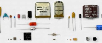
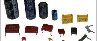
Flat capacitor
There are many types of capacitors with different shapes and internal structures. Let's consider the simplest and most fundamental - a flat capacitor. A flat capacitor consists of two parallel conductor plates (plates), electrically insulated from each other by air or a special dielectric material (for example, paper, glass or mica).
Determination of the resulting capacitor resistance
The resulting resistance of a capacitor cannot be found by summing the values of its active and capacitive resistances. This is done according to the formula
Tweet Like
- Previous post: AC Power
- Next entry: Checking radio components
- What is the difference between current and voltage? (2)
- Current and Voltage Relationship (0)
- POWERFUL AUDIO AMPLIFIER HA LM383 (0)
- POWER SUPPLY FOR CAR RADIO (0)
- BATTERY CHARGER (0)
- LITHIUM-NON CELL CHARGER CHARGER CONTROLLER (0)
- BATTERY CHARGING CURRENT LIMITER (0)