Electrical circuits use different types of connections. The main ones are serial, parallel and mixed connection schemes. In the first case, several resistances are used, connected in a single chain one after another. That is, the beginning of one resistor is connected to the end of the second, and the beginning of the second to the end of the third, and so on, up to any number of resistances. The current strength in a series connection will be the same at all points and in all sections. To determine and compare other parameters of the electrical circuit, other types of connections that have their own properties and characteristics should be considered.
Calculation of simple DC circuits
In electrical engineering, it is generally accepted that a simple circuit is a circuit that reduces to a circuit with one source and one equivalent resistance. You can collapse a circuit using equivalent transformations of serial, parallel, and mixed connections. The exception is circuits containing more complex star and delta connections. DC circuits are calculated using Ohm's and Kirchhoff's laws.
Example 1
Two resistors are connected to a 50 V DC voltage source, with an internal resistance of r = 0.5 Ohm. The resistances of resistors R1 = 20 and R2 = 32 Ohms. Determine the current in the circuit and the voltage across the resistors.
Since the resistors are connected in series, the equivalent resistance will be equal to their sum. Knowing it, we will use Ohm's law for a complete circuit to find the current in the circuit.
Now knowing the current in the circuit, you can determine the voltage drop across each resistor.
There are several ways to check the correctness of the solution. For example, using Kirchhoff's law, which states that the sum of the emf in the circuit is equal to the sum of the voltages in it.
But using Kirchhoff's law it is convenient to check simple circuits that have one circuit. A more convenient way to check is the power balance.
The circuit must maintain a power balance, that is, the energy given by the sources must be equal to the energy received by the receivers.
The source power is defined as the product of the emf and the current, and the power received by the receiver as the product of the voltage drop and the current.
The advantage of checking the power balance is that you do not need to create complex cumbersome equations based on Kirchhoff's laws; it is enough to know the EMF, voltages and currents in the circuit.
Example 2
The total current of a circuit containing two resistors R 1 = 70 Ohm and R 2 = 90 Ohm connected in parallel is 500 mA. Determine the currents in each of the resistors.
Two resistors connected in series are nothing more than a current divider. We can determine the currents flowing through each resistor using the divider formula, while we do not need to know the voltage in the circuit; we only need the total current and the resistance of the resistors.
Currents in resistors
In this case, it is convenient to check the problem using Kirchhoff’s first law, according to which the sum of currents converging at a node is equal to zero.
If you have any difficulties, read the article Kirchhoff's laws.
If you do not remember the current divider formula, then you can solve the problem in another way. To do this, you need to find the voltage in the circuit, which will be common to both resistors, since the connection is parallel. In order to find it, you must first calculate the circuit resistance
And then the tension
Knowing the voltages, we will find the currents flowing through the resistors
As you can see, the currents turned out to be the same.
Example 3
In the electrical circuit shown in the diagram R 1=50 Ohm, R 2=180 Ohm, R 3=220 Ohm. Find the power released through resistor R 1, the current through resistor R 2, the voltage across resistor
R 3, if it is known that the voltage at the circuit terminals is 100 V.
To calculate the DC power released through resistor R1, it is necessary to determine the current I1, which is common to the entire chain. Knowing the voltage at the terminals and the equivalent resistance of the circuit, you can find it.
Equivalent resistance and current in the circuit
Hence the power allocated to R1
We determine the current I2 using the current divider formula, taking into account that the current I1 for this divider is common
Since the voltage when connecting resistors in parallel is the same, we find U3 as the voltage across resistor R2
This is how simple DC circuits are calculated.
- electroandi.ru
Online calculator for parallel connection of resistors
It is not difficult to manually calculate the series connection of resistors. But for parallel and combined circuits it is more convenient to use a calculator. The corresponding services are offered free of charge by reference and thematic websites.
Specialized modern software provides automated calculation of operating parameters of complex circuits. The user can:
- rearrange conductors;
- install LEDs, capacitors, and other components in the right place;
- change the input signal.
Application “simulator” of electrical circuits for mobile devices on Android OS
The information presented in the publication will be useful for independent calculations and checks. It will help you choose a resistor in the store and restore the functionality of the electrical device.
calculation rules for determining current strength
In practice, a number of methods have been developed for defining and calculating constant current circuits, which makes it possible to reduce the time-consuming process of calculating complex electrical circuits. The basic laws by which the characteristics of almost every scheme are determined are Kirchhoff's postulates.
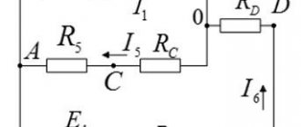
Example of complex electrical circuits
Ways to calculate electrical circuits
The calculation of electrical circuits branches into many methods used in practice, namely: the method of equivalent transformations, a technique based on Ohm's and Kirchhoff's postulates, the superposition method, the method of loop currents, the method of nodal potentials, the method of an identical generator.
The process of calculating an electrical circuit consists of several mandatory steps that allow all calculations to be made fairly quickly and accurately.
Before finding out or calculating the necessary parameters, the calculated electrical circuit is transferred schematically to paper, which contains symbolic designations of its constituent elements and the order of their connection.
All elements and devices are divided into three categories:
- Power supplies. The main feature of this element is the conversion of non-electric energy into electrical energy. These energy sources are called primary energy sources. Secondary energy sources are devices whose inputs and outputs contain electrical energy. These include rectifiers or voltage transformers;
- Devices that consume electrical energy. Such elements convert electrical energy into any other energy, be it light, sound, heat and the like;
- Auxiliary circuit elements, which include connection wires, switching equipment, protection and other similar elements.
Also, the basic concepts of an electrical circuit include:
Designation of branches, nodes and contours in the diagram
Calculation method according to Ohm's and Kirchhoff's laws
These laws allow you to find out the current strength and find the relationship between the values of currents, voltages, EMF of the entire circuit and individual sections.
Ohm's law for a circuit section
According to Ohm's law, the relationship between current, voltage and circuit resistance looks like:
UR=RI.
Based on this formula, the current strength can be found using the expression:
I=UR/R, where:
- UR – voltage or voltage drop across the resistor;
- I is the current in the resistor.
Ohm's law for a complete circuit
Ohm's law additionally uses the internal resistance of the power source for the complete circuit. It is possible to find the current strength taking into account the internal resistance using the expression:
I=E/Re = E/r0+R, where:
- E – EMF of the power source;
- rо – internal resistance of the power source.
Since a complex electrical circuit, consisting of several branches and having a number of power devices in its structure, cannot be described by Ohm’s law, the 1st and 2nd Kirchhoff’s laws are used.
Kirchhoff's first law
Kirchhoff's law states that the sum of currents flowing into a node is equal to the sum of currents flowing out of it, it looks like:
∑mIk=0, where m is the number of branches connected to the node.
According to Kirchhoff's law, currents flowing into a node are used with a “+” sign, and currents flowing out of a node are used with a “-” sign.
Kirchhoff's second law
From Kirchhoff’s second law it follows that the sum of the voltage drops across all elements of the circuit is equal to the sum of the EMF of the circuit, looks like:
∑nEk=∑mRkIk=∑mUk, where:
- n – number of EMF sources in the circuit;
- m – number of elements with resistance Rk in the circuit;
- Uk=RkIk – voltage or voltage drop on the kth circuit element.
Before applying Kirchhoff's second law, the following requirements should be checked:
- Indicate relatively positive directions of EMF, currents and voltages;
- Indicate the direction of traversal of the contour described by the equation;
- Applying one of the interpretations of Kirchhoff’s 2nd law, the characteristics included in the equation are used with a “+” sign if their relatively positive directions are similar to the circuit bypass, and with a “-” if they are opposite directions.
From Kirchhoff's 2nd law follows an expression for the power balance, according to which the power of power sources at any time is equal to the sum of the powers consumed in all sections of the circuit. The power balance equation has the form:
∑EI=∑RI2.
Electrical circuit conversion method
Elements in electrical circuits can be connected in parallel, in series, in a mixed way, and according to “star” and “triangle” circuits. The calculation of such circuits is simplified by replacing several resistances with an equivalent resistance, and further calculations are already carried out according to Ohm's or Kirchhoff's law.
Serial and parallel connection of elements
A mixed connection of elements means the simultaneous presence in the circuit of both serial and parallel connection of elements. In this case, the resistance of the mixed connection is calculated after converting the circuit into an equivalent circuit using the formulas shown in Fig. higher.
There is also a connection of elements with a “star” and a “triangle”. To find the equivalent resistance, you must first convert the delta to star circuit. According to the picture below, the resistances are equal:
- R1=R12R31/R12+R31+R23,
- R2=R12R23/R12+R31+R23,
- R3=R31R23/R12+R31+R23.
Triangle and star connections
Additional circuit calculation methods
All additional methods for calculating circuits to one degree or another are or are based on Kirchhoff's first and second laws. These methods include:
- Loop current method – based on the introduction of additional values of loop currents that satisfy Kirchhoff’s 1st law;
- Nodal potential method - with its help, the potentials of all nodes of the circuit are found and then, using known potentials, the currents in all branches. The method is based on Kirchhoff's first law;
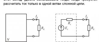
- Equivalent generator method - this method provides a solution to the problem of how to find the current in only one or several branches. The essence of the method is that any electrical circuit in relation to the branch under study can be represented as an equivalent generator;
- The superposition method is based on the fact that the current in a circuit or circuit branch is equal to the algebraic sum of the currents induced by each source separately.
The main part of the calculation methods is aimed at simplifying the procedure for determining currents in the branches of the circuit. These measures are carried out either by simplifying the systems of equations used for calculations, or by simplifying the scheme itself. Based primarily on Kirchhoff's postulates, any of the methods answers the question: how to determine the current strength and voltage of an electrical circuit.
Video
Rate the article:
elquanta.ru
Using the Joule-Lenz law
Some find it difficult to determine the current strength if there is:
- Time;
- Resistance value;
- The amount of heat generated from the conductor.
To solve the problem, you need to use the Joule-Lenz law: Q=I2Rt
Based on this formula, the calculation should be constructed as follows: I2=QRt
Or like this: I=(Q/Rt)1/2
Ohm's law for a complete circuit
If almost everyone knows Ohm's law for a section of a circuit, then Ohm's law for a complete circuit causes difficulties for schoolchildren and students. It turns out that everything is painfully simple!
Ideal EMF source
We have an EMF source
Let's remember what EMF is. EMF is something that creates an electric current. If we connect any load to such a voltage source (even a billion halogen lamps connected in parallel), it will still produce the same voltage as it would have produced if we had not connected any load at all.
Or simpler:
In short, no matter how much current passes through the resistor circuit, the voltage at the ends of the EMF source will always be the same. Such an EMF source is called an ideal EMF source .
But as you know, nothing is ideal in our world. That is, if our battery had an ideal source of EMF, then the voltage at the battery terminals would never sag. But it sags, and the more, the more current the load consumes. Something is wrong here. But why does this happen?
Internal resistance of the EMF source
The thing is that a resistance is “hidden” in the battery, which, relatively speaking, clings in series with the source of the battery’s emf. It is called internal resistance or output resistance. Indicated by a small letter “ r ”.
It all looks like this in the battery:
We hook the light bulb
So, what do we get in its pure form?
A light bulb is a load that has resistance. So, we simplify the diagram even more and get:
We have an ideal EMF source, internal resistance r and load resistance R. Recall the article voltage divider. It says that the voltage of the EMF source is equal to the sum of the voltage drops across each resistance.
The voltage UR drops across the resistor R, and the voltage Ur drops across the internal resistor r.
Now let's remember the article current divider. The current flowing through series-connected resistances is the same everywhere.
Let's remember algebra for 5th grade and write down everything that we just talked about. From Ohm's law for a section of the chain we obtain that
Further
Ohm's law for a complete circuit
So, the last expression is called “Ohm’s law for a complete circuit”
Where
E – EMF of the power source, V
R – resistance of all external elements in the circuit, Ohm
I – current in the circuit, A
r – internal resistance of the power source, Ohm
Voltage sag
So, meet the car battery!
For further use, solder two wires to it: red to positive, black to negative
Our ward is ready for battle.
Now we take a car halogen light bulb and also solder two wires with alligators to it. I soldered to the terminals for the “low” beam.
First of all, let's measure the voltage at the battery terminals
12.09 volts. This is quite normal, since our battery produces exactly 12 volts. Let me jump ahead a little and say that now we have measured the EMF.
We connect the halogen lamp to the battery and measure the voltage again:
Have you seen it? The voltage at the battery terminals dropped to 11.79 Volts!
Let's measure how much current our lamp consumes in Amperes. To do this, we create the following diagram:
The yellow multimeter will measure voltage, and the red multimeter will measure current. You can read how to measure current and voltage using a multimeter in this article.
Let's look at the instrument readings:
As we can see, our lamp consumes 4.35 Amperes. The voltage dropped to 11.79 Volts.
Let's replace the halogen lamp with a simple 12 Volt incandescent lamp from a motorcycle
Let's look at the readings:
The light bulb consumes a current of 0.69 Amps. The voltage dropped to 12 volts exactly.
What conclusions can be drawn? The more current the load consumes, the more the battery voltage drops.
How to find the internal resistance of an EMF source
Let's go back to this photo again
Since in this case the circuit is open (there is no external load), therefore the current in circuit I is equal to zero. This means that the voltage drop across the internal resistor Ur will also be zero. As a result, we are left with only the EMF source, from which we measure the voltage. In our case, EMF = 12.09 Volts.
As soon as we connected the load, the voltage immediately dropped across the internal resistance and the load, in this case the light bulb:
Now at the load (on a halogen) the voltage drops UR = 11.79 Volts, therefore, at the internal resistance the voltage drop is Ur = E-UR = 12.09-11.79 = 0.3 Volts. The current strength in the circuit is equal to I = 4.35 Amperes. As I already said, our EMF is equal to E = 12.09 Volts. Therefore, from Ohm’s law for a complete circuit we calculate what our internal resistance r will be equal to
Summary
Internal resistance occurs not only in various chemical voltage sources. Various measuring instruments also have internal resistance. These are mainly voltmeters and oscilloscopes.
The point is that if we connect a load R, the resistance of which is less than or even equal to r, then the voltage will drop very significantly. This can be seen if you short-circuit the battery terminals with a thick copper wire and measure the voltage at the terminals at this time. But I do not recommend doing this under any circumstances! Therefore, the higher the resistance of the load (that is, the higher the load resistance R), the less influence this load has on the source of electrical energy.
When measuring voltage, a voltmeter and an oscilloscope also slightly drain the voltage of the voltage source being measured, because they are loads with high resistance. This is why the most accurate voltmeter and oscilloscope have a very high resistance between their probes.
www.ruselectronic.com
Direction of electric current in metals
Negatively charged electrons move along metal wires, i.e. current flows from “–” to “+” source. The direction of electron motion is called real. But historically in science, the conditional direction of current is accepted from “+” source to “–”.
Actions of electric current (energy conversion)
Electric current can cause various actions:
- Thermal - electrical energy is converted into heat. This transformation is provided by an electric stove, electric fireplace, and iron.
- Chemical - electrolytes undergo electrolysis under the influence of direct electric current. During electrolysis, negative ions (anions) are attracted to the positive electrode (anode), and positive ions (cations) are attracted to the negative electrode (cathode).
- Magnetic (electromagnetic) - in the presence of an electric current in any conductor, a magnetic field is observed around it, i.e. a conductor carrying current acquires magnetic properties.
- Luminous - electric current heats metals to white heat, and they begin to glow like a tungsten spiral inside an incandescent lamp. Another example is LEDs, in which light comes from the emission of photons as an electron moves from one energy level to another.
- Mechanical - parallel conductors with electric currents flowing in one direction attract, and in opposite directions they repel.
Voltage formula. How to find and calculate electrical voltage.
Topic: how to calculate the voltage value knowing the current, resistance, power.
As you know, electrical voltage must have its own measure, which initially corresponds to the value that is calculated to power a particular electrical device. Exceeding or decreasing the value of this supply voltage negatively affects electrical equipment, up to its complete failure. What is tension? This is the electrical potential difference. That is, if, for ease of understanding, it is compared with water, then this will approximately correspond to pressure. According to science, electrical voltage is a physical quantity that shows how much work a current does in a given area when a unit charge moves through this area.
The most common voltage-current formula is one in which there are three basic electrical quantities, namely voltage itself, current and resistance. Well, this formula is known as Ohm’s law (finding electrical voltage, potential difference).
This formula sounds like this: electrical voltage is equal to the product of current and resistance. Let me remind you that in electrical engineering there are different units of measurement for various physical quantities. The unit of measurement for voltage is “Volt” (in honor of the scientist Alessandro Volta, who discovered this phenomenon). The unit of current is “Ampere” and resistance is “Ohm”. As a result, we have - an electrical voltage of 1 volt will be equal to 1 ampere multiplied by 1 ohm.
In addition, the second most used voltage formula is the one in which this same voltage can be found knowing the electrical power and current strength.
This formula sounds like this: electrical voltage is equal to the ratio of power to current (to find voltage, you need to divide power by current). The power itself is found by multiplying the current by the voltage. Well, to find the current you need to divide the power by the voltage. Everything is extremely simple. The unit of measurement for electrical power is “Watt”. Therefore, 1 volt is equal to 1 watt divided by 1 ampere.
Well, now I’ll give a more scientific formula for electrical voltage, which contains “work” and “charges”.
This formula shows the ratio of the work done to move an electric charge. In practice, you are unlikely to need this formula. The most common one will be the one that contains current, resistance and power (that is, the first two formulas). But, I want to warn you that it will only be true for the case of using active resistances. That is, when calculations are made for an electrical circuit that has resistance in the form of ordinary resistors, heaters (with a nichrome spiral), incandescent light bulbs, and so on, then the above formula will work. In the case of using reactance (the presence of inductance or capacitance in the circuit), you will need a different current voltage formula, which also takes into account the frequency of the voltage, inductance, and capacitance.
PS The formula of Ohm's law is fundamental, and it is by it that you can always find one unknown quantity out of two known ones (current, voltage, resistance). In practice, Ohm's law will be used very often, so it is simply necessary for every electrician and electronics engineer to know it by heart.
electrohobby.ru
What is the total current of the circuit and the voltage in the section with a series connection???
The total resistance in a series connection is equal to the sum of the resistances Rsum=R1+R2+R3... One current flows through all resistances (I). Therefore, you calculate the current as the ratio of the source voltage U to Rtotal. I=U/Rsum Power P=U*I or P=I*I*R (since U=I*R). then, P1=I*I*R1 P2=I*I*R2 P3=I*I*R3
where is the source data?
1) sum 2) voltage on a section of the circuit multiplied by current. Moreover, the current in a series connection is the same at any point in the circuit
The sum of the currents in the node is zero. The output is equal to the input. 1) fold. 2) the sum of the powers of the circuit elements.
With a serial connection there are no nodes. Circuit current is determined by dividing the applied voltage in volts (V) by the circuit resistance in ohms (R). I=V : R. The voltage drop across the section will be equal to the section resistance multiplied by the current. The total resistance is equal to the sum of all resistances. The power of a section is equal to the voltage drop across the section multiplied by the current. This is Ohm's Law. Actually, this is all in the school physics textbook in the Electricity section.
touch.otvet.mail.ru
Types of electrical conductor connections
The main connection schemes are parallel and serial connection. There are also combinations of these two inclusions.
Sequential
With a serial (in foreign terminology serial) connection, the terminals of the elements are connected so as to form a chain. One terminal of the device is connected to one adjacent link, and the second to another, on the opposite side.
Serial connection and practical application example.
An example of such a connection is the standard connection of an LED and a resistor. The resistor is needed as a current-limiting ballast.
Parallel
When connected in parallel, the same terminals of the circuit elements are connected to each other. A practical example is lamps in a multi-light chandelier or turn signal repeaters in a car.
Parallel connection and practical example.
Mixed
In one circuit, the connection diagram can be combined - serial + parallel. Some elements are connected in parallel, forming links. These links can be included in a sequential chain. Or vice versa - serial circuits are connected in parallel.
Combined connection of conductors.
This circuit is used, for example, in LED strips. In it, chains of current-limiting ballasts and radiating diodes are connected in parallel.
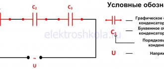
AC Circuit Voltage | For electricians
Variable voltage is voltage that changes over time. Further we will consider only harmonic alternating voltage (varies along a sinusoid).
u = U
m
sin(2πt + Ψ ) =
U msin(ωt + Ψ )
Where u = u(t) is the instantaneous value of alternating voltage [V].
U
m - maximum voltage value
(amplitude value) [V].
f - frequency equal to the number of oscillations per second (frequency unit - hertz (Hz) or s-1)
ω - angular frequency (omega) (unit of angular frequency - rad/s or s-1)
ω = 2πf = 2π/T
The argument of the sine, i.e. ( ωt + Ψ ), is called the phase . The phase characterizes the state of oscillation (numerical value) at a given time t.
U - Effective voltage value [V]:
Let's consider the voltage parameters in a household electrical network.
We all know that in our home, alternating current is supplied to the outlet, with a voltage of 220 volts and a frequency of 50 hertz (under ideal conditions), in fact, a small error is allowed, both downward and upward, so don’t be surprised if your the voltmeter will show not 220, but for example 210 or even 230 V.).
Most devices measure not the amplitude, but the effective value of alternating voltage, current, power, so that if we say that our network voltage is 220, 380 V, etc., then we mean the actual values.
- Effective voltage value U = 220 V.
- The amplitude value of the AC circuit voltage Um = U*√2 = 220 *√2 = 311 V.
- Angular frequency ω = 2πf = 3.14*2*50 = 314 rad/s.
- Initial phase Ψ = 0 deg .
- Instantaneous value u 311sin (314t) V.
electrickam.com
Video
Coffee capsules Nescafe Dolce Gusto Cappuccino, 8 servings (16 capsules)
435 ₽ More details
Coffee capsule Nescafe Dolce Gusto Cafe O Le Coffee with milk, 3 packs of 16 capsules each
1305 ₽ More details
The best tablets