Principle of operation
A megohmmeter is a useful invention that can be used to check the performance of the insulating layer in wiring. The device is classified as professional, but most modern models support several functions at once, for example, analyzing the state of the electrical network, checking the exact voltage, and so on. In this regard, many people want to purchase their own megohmmeter to use it for household tasks.
Using special probes, the device is connected to the line being measured and then started. Each device is equipped with a constant voltage source that generates high voltage to test insulation. As for the basic functions and set of calibration voltages, they differ depending on the specific model. If cheap options have only one operating mode, then more expensive ones are characterized by high performance and combined capabilities.
are currently available on the market :
- Older models equipped with a built-in dynamo. To start the device you need to turn a special handle.
- New devices with electronic circuitry. They are connected to a household electrical outlet or internal batteries, using them as a voltage source. Among the supported modes and functions there is not only monitoring of wiring insulation, but also assessment of current voltage, low-resistance resistance and other parameters. In fact, many models can replace a multimeter, since the range of calibration voltages is quite wide.
The calibrated voltage and its value are set using a special switch. For precise tuning, it is necessary to take into account the type of system that can be analyzed. The resulting measurements will be shown on the screen or corresponding scale. To simplify the process of studying the results, in pointer-type models the scale is calibrated in KOhm or MOhm.
The operating principle of the invention is based on Ohm's simple physical law: I = U / R.
Megaohmmeter - attachment to a multimeter
This easy-to-use attachment, together with the 83x series multimeter, which has a maximum active resistance measurement limit of 2 MΩ, allows you to directly measure the resistance of resistors and high-resistance circuits up to 20 MΩ. No additional power source is required for the set-top box.
It is known that inexpensive and popular among radio amateurs, multimeters of the 83x series do not allow measuring active resistance of more than 2 MOhm without additional components or calculations. The proposed attachment expands the measurement limits to 20 MOhm. The value of the measured resistance is displayed on the multimeter display. As in other set-top boxes developed by the author, power (+3 V) is supplied to it from the internal stabilizer of the multimeter ADC chip.
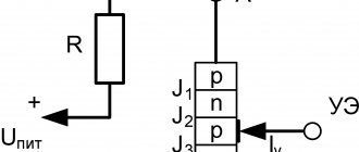
The attachment diagram is shown in Fig. 1. A current source (IT) is assembled using op-amp DA1.1 and resistors R3-R6 according to a circuit known in the radio engineering literature as Howland IT. The author has already used such a node in his earlier development [1]. Its output current is calculated based on the following conditions: R3 = R5, R4 = R6 for the convenience of their subsequent selection; the current through resistor R6 is equal to the algebraic sum of the currents through resistor R3 and the measured resistor Rx; input currents of op-amp DA1 are negligible. The op-amp is covered by deep OOS for direct current through the divider R4R5, therefore, equal voltages are set at both its inputs (inverting and non-inverting) if the output voltage is less than the maximum at a given supply voltage. In this case, the IT output current (Iout) will be equal to: Iout = UR2/3, where UR2 is the voltage at the output of the resistive divider R1R2 (i.e., across the resistor R2). This voltage serves as a reference voltage for IT, since the resistance of resistor R2 is significantly less than the resistance of resistor RЗ.
Rice. 1
The IT output current is chosen to be 0.1 μA, and it is quite enough to measure the resistance of resistors up to 20 MOhm, since the voltage drop across it will not exceed 2 V, which is less than the supply voltage of the set-top box (3 V). With the resistances of resistors R3-R6 indicated in the diagram, the DA1.1 op-amp is guaranteed to operate in linear mode, providing high stability and constancy of the IT output current flowing through the measured resistor Rx, and therefore a high linearity of the dependence of the voltage drop across the measured resistor or circuit. This voltage is supplied to the input of a buffer amplifier, made using op-amp DA1.2 (input resistance - at least 1 GOhm) with unity voltage gain. To interface with the multimeter, use a resistive voltage divider R7R8, which reduces the voltage at the output of op-amp DA1.2 tenfold. From the output of the divider it goes to the “VΩmA” input of the multimeter for subsequent measurement.
The current consumption of the set-top box is almost equal to the current consumption of the DA1 microcircuit. The error in measuring resistance in the range from 2 to 19.99 MOhm is no more than 3%.
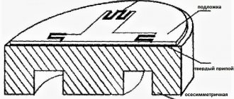
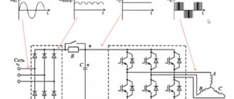
The attachment is assembled on a board made of fiberglass foil on one side; its drawing is shown in Fig. 2, the location of the elements on it is shown in Fig. 3. The MCP602 op amp can be replaced with the domestic KR1446UD4A op amp (in DIP8 housing) [2]. When replacing with another Rail-to-Rail op-amp, it should be taken into account that its inputs must be made of field-effect transistors (input resistance - at least 1 GOhm), the minimum supply voltage - no more than 3 V and current consumption (per case) - no more 3 mA. To reduce the error when measuring resistances less than 2 MOhm, the zero offset voltage should not exceed 1...2 mV. Blocking capacitor C1 - tantalum K53-1, resistors - MLT, S2-33, high-resistance - KIM. Pairs of resistors R3 and R5, R4 and R6 should be selected using a multimeter with a resistance deviation of no more than 1% in each pair. In this case, the deviation of the resistance from the nominal does not affect the measurement accuracy - their equality is important. The resistances in each pair can be reduced to 1.5 MOhm and 300 kOhm, respectively. In this case, the voltage on resistor R2 must be reduced based on the equality UR2(V) = 0.1xRZ (MΩ). For example, if RЗ = R5 = 1.6 MOhm, R4 = R6 = 330 kOhm, then R1 = 27 kOhm, R2 - 1.6 kOhm. Pin XP1 - suitable from the connector or a piece of tinned wire of a suitable diameter. The hole for it in the board is drilled “in place” after installing the XP2, XP3 pins. Pins ХР2 and ХРЗ are from multimeter probes. Input jacks XS1, XS2 - screw terminal block ED350V-02P from DINKLE or similar.
Rice. 2
Rice. 3
When working with the attachment, the switch for the type of operation of the multimeter is set to the position of measuring direct voltage at the “200mV” limit. Before calibration, in order to avoid failure of the internal +3 V ADC stabilizer, the set-top box is first connected to an autonomous power source with a voltage of 3 V (two 1.5 V galvanic elements connected in series can be used) and the current consumption is measured, which should not exceed 3 mA, and then connect to a multimeter. Next, calibration is carried out by connecting a resistor with a resistance of several megaohms with a known resistance or an accuracy class of no worse than 1% to the XS1, XS2 “Rx” sockets. By selecting resistor R7, the desired readings on the indicator are achieved. The readings, taking into account the comma, are divided by ten. Please note that to facilitate calibration, resistor R7 on the board is made up of two resistors connected in series. In Fig. 3 they are designated as R7′ and R7“.
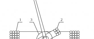
The photograph (Fig. 4) shows an attachment connected to a multimeter when measuring a KIM-0.125 resistor with a nominal resistance of 15 MOhm and a permissible deviation from the nominal value of ±10%.
Rice. 4
LITERATURE
- Glibin S. LC-meter - an attachment to a multimeter. - Radio, 2014, No. 8, p. 21-24.
- KR(KF)1446UDxx operational amplifiers. - URL: https://www.qrz.ru/reference/tісго/сіаіазьеІ/1446ud.pdf
Author: S. GLIBIN, Moscow Source: Radio No. 5, 2015
Device and design
Most models of such measuring instruments include a DC generator, a measuring head, a switch, and current-limiting resistors. This unit provides switching of any resistor circuits that affect the output voltage and operating mode.
All components of the megohmmeter are combined in one housing with a durable dielectric coating. For convenient transportation, the device is equipped with a comfortable handle on which a portable generator handle is placed. To start the device, simply unfold the handle and start rotating.
You might be interested in Electrical engineering and electronics as the basis of physics
The operating principle of devices with internal or external power supply does not differ from mechanical models with a handle. To produce the required voltage, just press the corresponding button and hold it until the desired values are achieved. Some devices can output different voltage combinations with a few simple buttons.
Modern models have a more complex internal structure. In this regard, they can produce different voltages, from 100 to 2500 V. In addition, individual devices are able to work with several ranges at once, which makes them highly efficient.
Models that can detect the insulation of high-voltage industrial equipment are more productive than those devices that only work on household wiring. Naturally, their sizes are very different.
Danger of high voltages
The built-in generator is characterized by output power indicators that are enough not only to assess the condition of the insulation, but also to cause a serious burn. Because of this feature, only trained electrical technicians with at least group 3 access to such devices are allowed to use the device.
When taking measurements using increased voltage, you need to cover the area being tested, terminals and wires. To ensure protection, probes with characteristic insulation are used. On one side they are fixed to the wires, and the other part is equipped with safety rings. As a result, it prevents you from touching exposed areas and prevents possible electric shock.
To carry out measurements, such devices provide a special working area that does not conduct current and is a safe place to hold. To connect to the circuit, use an alligator clip with good insulation. Any other wires or stand-alone probes are not allowed. In addition, to increase the safety of the procedure, the area being tested must be isolated from strangers. This is especially important when checking resistance in long cables with a length of up to several kilometers.
As for the induced voltage , it plays a significant role in the accuracy of the measurements. Electricity that passes through power transmission line wires is capable of creating a certain magnetic field, measured taking into account the sinusoidal law. If the cable has an impressive length, this voltage becomes very high.
Depending on this factor, the measurement accuracy varies significantly. This is explained by the fact that the magnitude and direction of the current passing through the device remain unknown. It occurs under the influence of induced voltage, and its indicators appear near the device’s own readings. As a result, the sum of two current quantities is displayed on the digital screen, and the task remains unsolved. Therefore, measuring insulation resistance in the presence of any type of voltage is a waste of time and effort.
You may be interested in this Definition of Ohm's law applied to a complete circuit
How to check a megohmmeter
Before starting the measuring work, an operation is performed to check the serviceable condition of the device and its leads; for this, the wires connected to the device are short-circuited and the generator handle is rotated, the arrow should show “0”; the short circuit is in the “I” switch position. When checking, while connecting the wires, you must not touch them with bare hands, as you may receive an electric shock.
How to use a megohmmeter or the sequence of measuring work:
- Connecting a megohmmeter to the resistance measurement sockets.
- Connecting the grounding conductor to the screen (casing) socket.
- Setting the switch to the desired measurement range, there are two of them, the higher the power of the equipment, the larger the measurement range.
- We check the operation of the device by closing the measuring probes while simultaneously rotating the handle.
- After connecting the measuring cords, rotate the handle of the megohmmeter (power generator), the speed should be at least 120 rpm.
- Moving the measurement arrow to a specific position is the start of the measurement report.
- To reduce the time it takes to measure resistance with a megohmmeter on scale II, short-circuit the resistance socket (before starting the measurement) and rotate the device knob for about 5 seconds.
- After using the megohmmeter, set the switch to the neutral position.
Fig No. 3. Megaohmmeter connection diagram
The permissible error in the operation of the megohmmeter is 0.05 Mohm + -15%. The additional error limit associated with the presence of industrial-frequency currents in the form of interference in the measurement circuit is about 500 μA. The device can be operated at temperatures ranging from 30 to +50 o C. At the terminals there is a measuring voltage of the megohmmeter from 500 to 2500V, depending on the measurement range used, therefore, upon completion of the measurement, it is necessary to discharge the generator by touching the “ground” with the measuring probes or short-circuit them for a second, between each other, until an electric discharge occurs.
Taking measurements
It’s not at all difficult to take any measurement or figure out how to work with a megohmmeter. But with such an activity, it is important to follow a certain sequence of actions and correctly move from one stage to the next. Before you begin, you should read the instructions and complete the preparatory steps.
First of all , you will need to disconnect the circuit under test from the specified load . If we are talking about the insulating layer in home wiring, it is enough to disconnect the power using a switch or a twist-out plug. When measuring the cables of a socket group, plugs must be removed from all sockets. When working with wiring for lighting fixtures, you need to unscrew the light bulbs from all chandeliers, spotlights and other equipment. Only after this can the verification begin.
The next stage of preparation is connecting an autonomous grounding. It will be needed in order to relieve residual voltage in the circuit. To do this, a copper wire with a cross-section of 1.5 square is fixed to the main bus in the shield. The opposite end must be stripped of insulation, so it is attached to a dry stick.
The wire is fixed in such a way that the copper comfortably touches the conductors.
Safety requirements
If we are talking about taking measurements using a megohmmeter at any enterprise, then it must be carried out by a trained specialist with an electrical safety group of 3 and above. Even during a home examination, it is important to adhere to basic rules and comply with safety requirements. So, according to the established instructions, each work with a megohmmeter must be carried out taking into account the following rules:
- The work should only be done with dielectric gloves (unfortunately, most people often miss this rule, but this is a mistake).
- Before you start work, you need to prepare the line and make sure that there are no people near it. Plants and factories should display posters warning “do not start”, “caution, high voltage” and so on. When measuring a long line at home, you can adhere to a similar principle - it is advisable to place a sign about the danger on the shield. You also need to familiarize yourself with the first steps when receiving an electric shock.
- During operation, the probes must be kept in the insulation area. Often, the handle has finger rests that are protected from high voltages.
- After completing the calculations, you need to connect the probes by crossing their non-insulated areas. In this way, residual stress can be relieved. Some electronic devices support an automatic discharge function, where the residual voltage is discharged after each measurement. If such a function is not available, you will have to perform the procedure yourself.
When performing calculations, special attention must be paid to residual stress. If the tested line is too long, the charge will become impressive and can cause serious damage to a person.
Line connection
The standard package includes three probes with different characteristics and structures. One of them has two tips and is designed to combat leakage currents. On the top side of the device there are three sockets for connecting probes. Each of them is characterized by a corresponding letter marking:
- Z - for connecting protection grounding.
- L is the line that is being measured.
- E - screen (intended to eliminate leakage currents).
You may be interested in this: Connecting a pass-through light switch according to the diagram
There are no other options, except for cases with shielded wiring. However, in private buildings such methods are not used, since the installation of cables with a screen is practically useless here. However, if you have this type of cable, you need to minimize the risk of leakage currents by using a probe with a split end. The wires of the shielding braid must be twisted into a bundle, adding to the general bundle of wires.
Taking measurements
After successfully solving all the problems, you can try to measure the wiring with a megameter. After successfully installing the probes, you should decide on the test voltage. When checking the insulation resistance, you need to apply a voltage of 500-1000 V, following the following instructions:
- First of all, it is necessary to prepare the object for measurements.
- Then you need to install a portable ground and move the switch to the desired position. You should also choose a measurement scale, taking into account the resistance value.
- You need to check the absence of voltage on the line using an indicator screwdriver or a multimeter, and then connect the probes to the measurement objects.
- All that remains is to remove the portable grounding and start taking measurements. If the work is carried out using an electronic device, then you need to press the “test” button on it. In manual models, you will have to turn the dynamo handle until the signal lamp lights up (this will confirm that the test voltage has been created).
- Having recorded the results obtained, all that remains is to disconnect the probes and take the residual voltage readings on the megohmmeter and the line.
If the indicators drop below a given level, you will have to act in two ways: either find the cause of the breakdown and eliminate it, or replace it.
Megaohmmeter operating principle and its diagram
Let's look at working with a megohmmeter using the example of the most common device labeled ES0202/2G. A device produced back in Soviet times at the Uman Instrument-Making Plant, the megaohmmeter became widespread throughout the entire Soviet Union and is currently operating successfully. Reliability, unpretentiousness, and most importantly, measurement accuracy have proven this device to be positive. In Russia, a device under this marking is produced in Belgorod and at many other instrument-making plants.
The device is designed for carrying out measurements with large resistance values, and is recommended for testing high-voltage equipment designed for high power, as well as for power cables with a large cross-section or spread over a considerable distance.
Figure No. 1: Appearance of the megohmmeter
A megaohmmeter of this type is an inductor device; it operates using a generator built into the design, which allows the device to operate without an external power source and without batteries.
The operating principle is based on the use of a schematic diagram of a logarithmic ratio measuring device. The measuring process involves: an electromechanical voltage generator, a converter and an electronic meter.
For operation, it is recommended to use intermittent mode, in which 1 minute is allotted for measurement, 2 minutes for a pause. When you first familiarize yourself with the device, carefully study the megohmmeter and the operating instructions.
Fig No. 2. Schematic diagram of the megohmmeter ES0202/2G
Insulation resistance
When understanding what a megohmmeter is needed for and how to work with it, it is important to know how to measure insulation resistance, since this task arises most often. When processing a cable that is already in use, it must be disconnected from the line and the load removed. In most cases, three-core wires are used in electrics, and only if it is necessary to connect a three-phase network, there are more of them.
When performing measurements, you need to turn all automatic switches on the panel to the “off” position, reduce the load and start working. If there is a screen on the cable (it is a braid of steel wire or aluminum tape), you need to use a probe with a forked tip, and add the screen to the bundle with the rest of the wiring and the “ground”.
How to use a megohmmeter, measuring insulation
Electrical networks are characterized by various parameters. One of the most important parameters of networks is electrical insulation. Insulation is any material that prevents electrical current from flowing in the wrong direction. Insulation can be the protective sheath of wires and cables. Devices such as insulators prevent conductive lines from contacting the ground. All these measures to isolate conductive parts are aimed at preventing short circuits, fires, or electric shock to humans.