A huge range of cable testers for diagnosing twisted pair and coaxial cables is available on the Russian market. How do these devices differ in their capabilities? Why do functionally similar devices have different prices? And how, without overpaying, can you choose a cable tester that is best suited for your purposes?
- Comparison of cable testers CableMaster 600 and NetCat Pro NC-500
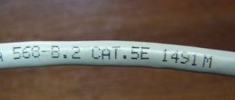
- Comparison of cable testers for SCS certification
Cable testers save a lot of time when testing twisted pair cables (with RJ45, RJ11, RJ22 connectors) and coaxial cables. They make it possible to determine the integrity of the conductors, the correct installation of connectors and the presence of damage. Today, manufacturers offer such a wide range of testers that choosing the right device is not an easy task even for an experienced engineer. Let's figure out what classes cable testers are divided into, what functionality they have, and why they differ in price.
For obvious reasons, we cannot cover all devices available on the market in one article. Therefore, let’s immediately make a reservation that we will be talking about high-quality, and therefore not the cheapest, cable testers from the brands Softing, Greenlee, Fluke Networks, Jonard, NetScout, Hobbes, DataShark.
Classification of cable testers
Devices can be roughly divided into classes based on their capabilities:
1. Testers for checking the correct crimping of twisted pair cables and the presence of damage.
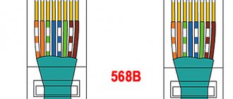
- Twisted pair crimping circuit (RJ45 pinout)
- Checking cable integrity
- Presence of mixed pairs, cable breakage, short circuit
2. Testers for determining installation errors with cable length measurement (by capacitance).
- To the functions already listed above, these devices add measurement of cable length and distance to break.
3. Professional testers for fault localization with cable length measurement (TDR method).
- To the above functions is added the measurement of distance to short circuit.
Let's look at each class in more detail.
PART 2. Testers for determining installation errors with cable length measurement (by capacitance)
It’s good when a technician has a twisted pair tester in his arsenal that shows the RJ45 pinout. With its help, you can check the correct installation of connectors immediately after crimping, make sure that the conductors are routed according to the required pattern, check the integrity of the cable, and make sure there are no breaks or short circuits. It’s doubly good if there are no problems and the connection is up. But what to do if a malfunction is discovered, or you come to an unknown line in order to repair it, or the connection is lost after rearranging furniture, drilling walls, driving in dowels, etc.?
The regular cable tester that was so good at pointing out faults to us is not very good at locating them. To find a problem in a cable, it is better to use devices that can measure its length. Simpler types of such devices measure the length of each pair of wires based on their capacitance. In fact, they measure not length, but capacity. However, taking advantage of the fact that this value is almost constant for a certain type of twisted pair, they themselves calculate the dependence and give us the result in meters. If the device is too deceptive with the length, you can simply adjust the specific capacitance value in the menu.
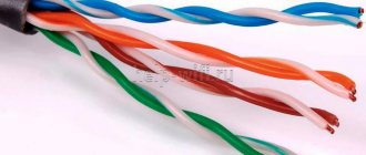
Please note that the tester measures each pair, not the cable as a whole. Even with the most accurate device, pair lengths of the same cable will vary. This is due to the different pitch of twisting of the conductors, which is done to reduce transient mutual influences during data transmission.
Using a tester with the ability to measure length by capacitance, we can measure the total length of the laid line or twisted pair cable UTP, FTP, STP (CAT7, 6A, 5e, 5, 3) in a coil, understand on which side the connector is not pressed (distance to violation integrity will be equal to the length of the cable or zero meters), and at what exact distance the break occurred if it happened in the middle of the line. The accuracy will be quite high. For example, for the Softing CableMaster 500 tester, the manufacturer claims ± 3% plus ± 30 cm. This means that over 100 meters of length the error will be no more than 3.3 meters. Someone will immediately say that this is a lot, and to accurately find the location of the break in the wall you need to know the point plus or minus a couple of centimeters. And he will be partly right. But even with zero error, how to measure, for example, 73 meters of cable from the connection point to the LAN tester, given that the wire is mostly hidden, has turns, bends, left margins, etc.? Answer: no way.
Having approximately seen the distance to the line break, you will determine the room, corridor, wall, or channel where the break theoretically occurred. Next, perform a visual inspection, and if this does not help, apply a tone signal from the built-in generator to the line. Then, using an inductive antenna probe, trace the cable, and by the difference in the level of the received signal you will find a violation of integrity. To get a good result, you will have to practice a little.
In general, cable testers with the ability to measure cable length allow you to find almost any cable damage or installation error. The difficulty will arise only when localizing the location of the short circuit. Due to the capacitance testing method, this is not possible since capacitance can only be measured on open-circuit conductors. But the price compared to the testers, which we will talk about in the 3rd part of the material, will be less high.
Examples of testers for measuring cable length (by capacitance):
CableMaster 500 Softing
Cable tester capabilities with cable length measurement (by capacitance):
- Digital LCD screen
- Connectors: RJ45, RJ11 and BNC (Coax) for data, voice and video cables
- Checking cable integrity, quality of twisted pair crimp and RJ45 (RJ11) pinout
- Detection of cable breaks, short circuits, mixed-up and split pairs
- Measuring the distance to a cable break
- Tone generator for cable testing
- Working with multiple remote identities
- Port voltage protection
Advantages of a twisted pair tester with cable length measurement (by capacitance):
- Ability to detect and locate cable breaks
- Very clear display of the measurement result in the form of a Pass/Fail message
- Fast and unambiguous interpretation of the type of damage
- Generator for cable tracing and selection (inductive probe required)
- Find the right ports quickly with multiple remote IDs
- Input voltage protection
- Protected housing
- Low battery indicator
- Auto power off
Disadvantages of a LAN tester with cable length measurement (by capacitance):
- Does not measure distance to short circuit
Output waveform (analog square wave, analog sine wave, digital)
The shape of the output signal also largely determines the characteristics of its propagation and the functionality of the tone generator.
Most test kits use an analog square wave signal. It creates small crosstalk on adjacent cable pairs, as a result of which the signal will also be heard on adjacent ports of the crossover. Moreover, the higher the generator frequency, the greater the crosstalk will be. However, the strongest signal at the return end of the cable will come from the pair into which the signal was applied, making it easy to identify this pair. This type of signal is also used in the generators presented in Table 1.
Half of the tone generators shown in Table 2 use an analog sine wave signal. Passing this signal to other pairs cancels itself out, resulting in very little crosstalk. This type of signal is most often used in cases where it is necessary to exclude the influence of test equipment on the operation of digital information transmission systems (ADSL). Using a capacitive receiver and an inductive probe, you can not only select the desired pair at the opposite end, but also select “your” cable from a bundle in the cable duct, trace the cable under plaster, behind a suspended ceiling, and even in the ground.
Table 2. Generator parameters. Part 2.
| Model/characteristics | 77GX | 600LS | DataMate (ADSL) | 600J |
| Providing a signal to identify cores in a multi-pair cable | • | • | • | • |
| Giving a signal to select a cable from a bundle | • | • | ||
| Determining the polarity of a telephone line | • | • | • | • |
| Wiring Continuity Testing | • | • | • | • |
| Estimation of loop resistance, capacitance and DC voltage | • | Loop and insulation resistance | ||
| Conversational Voltage Supply | • | • | • | • |
| Connection via coupling capacitor / (ADSL compatible) | • | • | ||
| Output waveform | rectangular | rectangular | sinusoidal | sinusoidal |
| Output signal frequency (analog), Hz | 577/984 Hz | 890/960 Hz | 877 / 982 Hz | 3 Hz; 5 Hz; 8.5 Hz; 11.5 Hz; 1 kHz |
| Output power/impedance | +8 dBm / 600 ohms | +7 dBm / 600 ohms | +9 dBm / 600 ohms | +13 dBm / 600 ohms |
| Visual indication of core short circuit | No | • | ||
| Sound indication of wire short circuit | • | No | No | |
| Polarity Determination | • | • | • | No |
| Supply voltage for test tube microphone | 5.5 V | 9.8 V | 7 V | No |
| DC input protection (impedance 600 ohms) | 60 V | 60 V | 52 V | 200 V |
| Line connection | crocodiles, RJ11 | crocodiles, RJ11 | crocodiles, RJ11, RJ45 | crocodiles |
Some test kits include the functionality of basic cable testers. The tone generators of these sets use a digital signal and send a digital map along with the trace signal to determine if the connector is installed correctly. A digital signal contributes to the appearance of significant crosstalk interference on adjacent pairs and even cables. This makes it easy to trace cables under plaster, in cavity walls and behind suspended ceilings, and to identify them at the return end. However, due to strong interference from neighboring pairs and cables, it will be almost impossible to select the desired pair. Therefore, such generators often allow you to generate a digital signal (for routing, selecting cables and checking the correct installation of the connector) along with an analog signal (for selecting cable pairs). Generators of this type are presented in Table 3.
Table 3. Tone generators with cable tester function
| Model/characteristics | 256711D | IT200 | AdapToner AT8 | LANToner 2 |
| Providing a signal to identify cores in a multi-pair cable | • | • | • | • |
| Giving a signal to select a cable from a bundle | • | • | • | |
| Determining the polarity of a telephone line | • | • | • | |
| Wiring Continuity Testing | • | • | • | • |
| Wiring of the cable under test to the terminal block built into the device | • | • | ||
| Wire diagram display | • | • | ||
| Conversational Voltage Supply | 6.5 V | 4.2 V | ||
| HUB port indication/display function (LED lights up) | • | |||
| Determining the presence of connected equipment | • | |||
| Determining the presence of an Ethernet line | • | • | ||
| Output waveform | Analog square wave / digital | Analog square wave / digital | Analog rectangular | Analog rectangular |
| Output signal frequency (analog), Hz | 1 kHz | 1 kHz | ||
| Output power/impedance | +10 dBm (5 V) | +10 dBm (5 V) | +7 dBm | +15 dBm |
| DC input protection (impedance 600 ohms) | 100 V | 60 V | 60 V | 60 V |
| Line connection | crocodiles, RJ45 | crocodiles, RJ11, RJ45 | crocodiles, RJ11, RJ45 | crocodiles, RJ11, RJ45 |
Determining the polarity of telephone lines
This function is most useful when servicing subscriber lines using blockers. The tables below indicate generators that have this function. Moreover, some of them allow you to determine the polarity of one line (when connected with crocodiles), others are able to determine the polarity of two pairs at the same time (when connected via RJ11).
Wiring Continuity Testing
This is a simple and very useful feature. It allows you to detect a short circuit in the line. Depending on the type of device, the detected short circuit between the wires is displayed using LED or sound indication.
Wiring of the cable under test to the terminal block built into the device
The function allows you to send a tone signal to the desired pair without disassembling the subscriber socket. It is implemented in the AdapToner AT8 and LANToner 2 generators
To implement this function when using other tone generators, you can use the GT-PA1902 modular adapters.
Organization of an official communication channel
The conversational voltage supply function allows you to organize an official communication channel between installers over a disconnected copper pair. The length of the line along which communication can be organized depends on the magnitude of the supply voltage. In different generators it ranges from 4.6 V to 9.8 V.
HUB port indication/display function (LED lights up)
In this mode, the test pattern generator sends special tones every 4.5 seconds. These signals cause the switch port LED to blink, making it easy to identify. A computer can be identified in the same way.
Function for determining the presence of connected equipment.
In this mode, the generator determines whether any active equipment is connected at the remote end of the cable. If equipment is connected from the remote side and it is in working condition, the “Found” LED on the generator lights up - found.
Wire diagram display
Devices with this functionality allow you to determine the presence and type of damage to a twisted pair (correct crimping): mixed up pairs, open circuit, short circuit. That is, they combine the functionality of a test kit and a simple cable tester.
Generators with this function are compatible only with “their” inductive probes.
Estimation of loop/insulation resistance, capacitance, voltage
This function is present in only one of the tone generators presented in table 2 - 600LS. The assessment result is indicated by sound signals. Moreover, a higher signal frequency corresponds to a larger value of the estimated parameter.
Security and fire alarm testing
A generator with the following functions – Greenlee 620K allows you to test:
- testing a normally open contact;
- testing a normally closed contact.
This will simplify the installation and testing of the functionality of security, fire and other alarm systems.
PART 3. Professional testers for fault localization with cable length measurement (TDR method)
This section is dedicated to professional cable testers with reflectometry technology, which many are already using, and even more specialists are just looking to use. Such testers make work easier and faster, help you find any cable damage and even measure the distance to a short circuit (some models only display the end of the cable where it occurred). True, a fully functional device from a good manufacturer costs a lot. For comparison, simple devices that test twisted pair cables, which we talked about at the very beginning, will cost about $30–50, but professional ones will cost $400–800.
Why is there such a difference and what do we pay for? The cost is justified by the wide capabilities of the equipment. But the need to have these capabilities depends only on the tasks assigned. There is no need to tell you that for a simple check of patch cords, professional testers will be good, but redundant in functionality.
Let's consider the capabilities of cable testers for measuring cable length and distance to short circuit (TDR) using the example of two devices. Softing CableMaster 600 and Greenlee NetCat Pro NC-500. They can test all categories of RJ45 twisted pair, telephone and coaxial cables.
You immediately notice the comfort of viewing the test results. All pairs are clearly displayed on one screen, and we can either quickly verify that everything is fine with the cable, or quickly identify the cause of the problem.
Comparison of cable testers CableMaster 600 and NetCat Pro NC-500
| Softing CableMaster 600 | Greenlee NetCat Pro NC-500 | Note |
| Measuring the length of the cable (each pair of wires). Checking the pinout of the RJ45 connector. Color display of all conductors (CableMaster 600). Confirmation of cable integrity. Display remote ID #1 (ID-1). Supports up to 8 remote RJ45 pinout IDs. | ||
| Testing Ethernet connectivity. Technology: 10 Base-T, 100 Base-TX, 100 Base-T4, 1000 Base-T. Availability of PoE and pairs through which power is supplied. CableMaster 600 has additional features: PoE standard recognition: IEEE 802.3af (up to 12.95W), PoE+ IEEE 802.3at (up to 25.5W), PoE type detection: A or B. Voltage test at min. and max. current load. | ||
| Measuring the distance to a cable break. Measuring the distance to a pair break. All information on one screen. There is no need to alternately control the length of each pair. Saving test results (CableMaster 600 only) | ||
| Measuring the distance to a short circuit. Measurement technology: pulse reflected (TDR*). * Time Domain Reflectometer - reflectometry. Variable pulse speed for different core sections. | ||
| Visualization of mixed up wires. Displays connector installation errors. | ||
| Display of a split pair (Split pair*) *installation error in which wires from two different pairs are combined into a “working” pair by mistake (the wires are not twisted). Not all testers are able to detect this defect. | ||
| Built-in tone generator. Selecting pairs (cores) through which to transmit a signal. Selecting the required cable from the bundle. Identifying the desired switch port. Cable routing in the wall. Compatible with any broadband antenna probe. |
A few words about how exactly the cable length is measured. The measurement is taken from one side of the line. A remote ID is not required, which is very convenient if you work alone. The tester sends a pulse into the line, which is reflected from the end of the cable and returns back to the device. The signal travel time in one direction is automatically calculated. Next, all that remains is to indicate to the device the speed of propagation of the pulse, and it will easily calculate the length using the simple formula L = V * T (where L is the distance, V is the speed of the pulse, T is time). In almost all devices, the pulse speed is designated as NVP (Nominal Velocity of Propagation), or VOP (Velocity of Propagation). This value depends on the category of twisted pair and the cross-section of the conductor; accordingly, it may differ slightly for similar cables from different manufacturers.
The ideal way to find out NVP is to calculate it. To get the best result, take a piece of twisted pair of known length, but not less than 30 m. Measure its length with a tester. If the device shows an incorrect cable length, adjust the NVP and repeat the measurement until the length determined by the device corresponds to reality. Ultimately, you will determine the pulse speed for a specific cable type. Read more about what NVP is and how to determine it in this article. And for those who don’t have time to read, let’s say that the Greenlee NC-500 tester already has a built-in editable table of cables with their corresponding coefficients, and the Softing CableMaster 600 has it printed directly on the battery compartment cover. There are no devices that themselves “understand” which cable is connected to them.
Testing multi-core cables for the purpose of marking them
When marking multi-core cables, you can use the methods described above, but there are ways to significantly simplify this process.
Method 1 : use of special transformers that have several secondary winding taps. The connection diagram for such a device is shown in the figure.
Using a transformer for marking
As can be seen from the figure, the primary winding of such a transformer is connected to the power supply network, one end of the secondary winding is connected to the protective shield of the cable, and the remaining terminals are connected to its conductors. To mark the wires, it is necessary to measure the voltage between the screen and each wire.
Method 2 : Use a block of resistors with different values connected to the cable wires on one side, as shown in the figure.
Resistors connected to cable terminals
To identify the cable, it is enough to measure the resistance between it and the screen. If you want to make such a device with your own hands, then you should select resistors in increments of at least 1 kOhm to reduce the influence of wire resistance. Also, do not forget that the value of the resistors has a certain error, so first measure them with an ohmmeter.
When checking a multi-core telephone cable, installers often use a dialing headset, for example TMG 1. Actually, these are two telephone handsets, one of which is connected to a 4.5 V battery. Such a simple device allows you not only to check the cable, but also to coordinate your actions during installation and testing.
Calling with a telephone handset
PART 4: Ethernet Speed Qualification Testers
Let's consider the capabilities of devices for speed qualification using the Softing NetXpert XG2-PLUS as an example.
The tester confirms the ability of a cable line (twisted pair, single-mode and multimode optics) to support the declared data transfer rate necessary for the smooth operation of Ethernet applications, enterprise automation systems, connected devices and machines. Operates at speeds: 100 MB, 1 Gbit, 2.5 - 5 Gbit, 10 Gbit.
The quality of cable installation and the environment in which it is located greatly influence the speed and accuracy of transmitted information. The device transmits real Ethernet data between the main and active remote units, which are installed on both sides of the communication line. This measures bit errors, signal propagation delay, and signal-to-noise ratio. A number of basic parameters are also checked: cable length (twisted pair and optical), pinout of the RJ45 connector, correct installation of the copper line, and even losses in the optical cable. The cleanliness of optical connectors can be checked using the optional video microscope.
The tester helps implement and maintain PoE devices powered over twisted pair cables: surveillance and security cameras, various sensors, access points, wired phones and other peripheral equipment. The device, simulating a powered device, measures the real voltage and power that reaches it and helps determine the problem segment: the PoE source, cable or device itself.
The device is capable of connecting to active networks via twisted pair, optical and Wi-Fi, while displaying the network configuration, connected devices and their names, it checks the functionality of DNS and DHCP servers, detects virtual VLANs, and tracks the data route. It also tests device availability using the Ping function and identifies problems associated with duplicate IP addresses. To increase service life, the device is equipped with a replaceable RJ45 port.
The device allows you to generate reports on the results of testing twisted pair, optical fiber and optical connectors in one software.
Market analysis showed the absence of domestic equipment manufacturers for such tasks. The set of functions of the Softing NetXpert XG2 PLUS tester is unique in its kind and has no analogues. Other testers do not combine in one device the capabilities of qualifying copper and optical lines, measuring the length of twisted pair and optics, measuring optical losses, troubleshooting twisted pair installation errors, testing PoE with load simulation, connecting to active networks over copper, optics and WiFi, perform the Ping function, track the data route. A good advantage is the replaceable RJ45 connector for connecting to the line, which significantly increases the service life of the device.
Comparison of Ethernet Speed Qualification Testers
| NetXpert XG2-1G NetXpert XG2-5G NetXpert XG2-10G | NetXpert XG2-PLUS | LinkIQ | |
| Manufacturer | Softing IT Networks | Softing IT Networks | Fluke Networks |
| Main unit of the tester | 1 PC | 2 pcs | 1 PC |
| Remote active block | 1 PC | 1 PC | |
| Remote passive block | 1 PC | ||
| RJ45 patch cords | 2 pcs | 2 pcs | 1 PC |
| Storage and transportation | case | case | bag |
| Speed qualification up to 1 Gbps | NX-XG2-1G (copper) | copper/optics | copper |
| Speed qualification up to 5 Gbps | NX-XG2-25-5G (copper) | copper | copper |
| Speed qualification up to 10 Gbps | NX-XG2-10G (copper) | copper/optics | copper |
| Cable qualification parameters and testing: | |||
| Ethernet Speed Qualification | 1G to 10G (copper) | 10G (copper/optics) | 10G (copper) |
| Signal to Noise Ratio (SNR) Test | ♦ | ♦ | |
| Number of bit errors (BERT) | ♦ | ♦ | |
| Signal delay offset per pair | ♦ | ♦ | |
| Optical fiber length measurement | option | ♦ | |
| Fiber Loss Measurement and Trend | option | ♦ | |
| Video microscope for optics | option | option | |
| Active remote block support | ♦ | ♦ | |
| Cable length (maximum) | up to 457 m | up to 457 m | up to 305 m |
| Cable length (method) | TDR/capacity | TDR/capacity | TDR |
| Distances to cable break | ♦ | ♦ | ♦ |
| Distances to short circuit | ♦ | ♦ | ♦ |
| Confused and split couples | ♦ | ♦ | ♦ |
| Colored RJ45 pinout diagram | ♦ | ♦ | ♦ |
| Signal generator (analog) | ♦ | ♦ | ♦ |
| Signal generator (digital) | ♦ | ||
| Remote ID support | up to 24 pcs | up to 24 pcs | up to 7 pcs |
| Replaceable RJ45 port | ♦ | ♦ | |
| Active Ethernet Network Testing: | |||
| Network connection interfaces | RJ45/SFP/Wi-Fi | RJ45/SFP/Wi-Fi | RJ45 |
| Network connection status and speed | ♦ | ♦ | ♦ |
| PoE testing up to 90W with load | ♦ | ♦ | ♦ |
| LLDP/CDP protocol support | ♦ | ♦ | ♦ |
| VLAN Discovery | ♦ | ♦ | ♦ |
| Finding the Switch Port Port ID | ♦ | ♦ | ♦ |
| Network structure, device display | ♦ | ♦ | |
| Ping to one IP or list of addresses | ♦ | ♦ | |
| Support for IPV4 and IPV6 protocols | ♦ | ♦ | |
| Checking the operation of DHCP and DNS | ♦ | ♦ | |
| Traceroute - data route | ♦ | ♦ | |
| PoE testing: | |||
| Polarity, type and class of PoE | ♦ | ♦ | ♦ |
| PoE power and voltage | ♦ | ♦ | ♦ |
| IEEE 802.3af PoE (Type 1, 15.4 W) | ♦ | ♦ | ♦ |
| IEEE 802.3at PoE+ (Type 2, 30 W) | ♦ | ♦ | ♦ |
| IEEE 802.3bt PoE++ (Type 3, 60 W) | ♦ | ♦ | ♦ |
| IEEE 802.3bt PoE++ (Type 4, 90 W) | ♦ | ♦ | ♦ |
| Reports and PC communication: | |||
| PDF report format | ♦ | ♦ | ♦ |
| Open CSV format | ♦ | ♦ | |
| Editable: MS-Excel, XML | ♦ | ♦ | |
| Initial test data: ".tst" | ♦ | ♦ | |
| Loading a company logo into a report | ♦ | ♦ | |
| Saving to external USB drive | ♦ | ♦ | |
| Interface for saving reports | USB type A | USB type A | USB type C |
| Memory, number of tests | > 100 000 | > 100 000 | 1 000 |
| Firmware update | ♦ | ♦ | |
| General characteristics: | |||
| Interface (twisted pair) | RJ45 (Cat 6A) | RJ45 (Cat 6A) | RJ45 |
| Interface (optics) | SFP 10G - 2 pcs. | SFP 10G - 2 pcs. | |
| Wi-Fi (2.4 and 5 GHz) | ♦ | ♦ | |
| Port voltage protection | 60 VDC/50 VAC | 60 VDC/50 VAC | ♦ |
| Display | 1024 x 600 | 1024 x 600 | 800 x 480 |
| Operating temperature | -10°C to 60°C | -10°C to 60°C | 0°C to 45°C |
| Dimensions | 245 x 177 | 245 x 177 | 216 x 114 mm |
| Weight | 1.2 kg | 1.2 kg | 624 g |
| Code: | NX-XG2-1G | NX-XG2-PLUS | LIQ-100 |
Tone Generator Output Power and Frequency
Due to the fact that the main function of tone generators is the generation of a tone signal, the main characteristic can be called the power and frequency of this signal.
Power is most often expressed in dBm or milliwatts, less often peak power is indicated in volts. However, it is most convenient for understanding to use dBm. Since, using them, it is easier to move on to the attenuation and length of the cable, which can be dialed using such a generator.
Example. Let's take the generator power to be +10 dBm (as can be seen in Table 1 below). Let's try to determine what the signal power will be at the output of a line 5 km long.
Using the formula for determining cable attenuation: A [dB] = P in [dBm] - P out [dBm], we determine the output attenuation:
P out [dBm] =
P in [dBm] - A [dB]
where:
- P out [dBm] – signal power at the line output;
- P input [dBm] – signal power at the line input = generator power;
- A [dB] – line attenuation.
It is known that the attenuation coefficient of a twisted pair communication cable TPP with a diameter of 0.5 mm at a frequency of 1 kHz = 1.5 dB / km
Table 1. Generator parameters
| Model/characteristics | 26200900 | 77M-G | 77HP-G | 77HP-G/6A |
| Manufacturer | Fluke Networks | Greenlee | Greenlee | Greenlee |
| Providing a signal to identify cores in a multi-pair cable | • | • | • | • |
| Determining the polarity of a telephone line | • | • | • | • |
| Wiring Continuity Testing | • | • | • | • |
| Supply of conversational voltage, determination of line status | No | • | • | • |
| Output signal frequency (analog), Hz | 1000/1500 Hz | 890/960 Hz | 890/960 Hz | 890/960 Hz |
| Output power/impedance | +8 dBm / 600 ohms | +10 dBm / 600 ohms | +10 dBm / 600 ohms | +10 dBm / 600 ohms |
| Visual indication of core short circuit | • | |||
| Sound indication of wire short circuit | No | No | ||
| Polarity Determination | • | • | • | • |
| Supply voltage for test tube microphone | No | 4.6 V | 4.6 V | 4.6 V |
| DC input protection (impedance 600 ohms) | 60 V | 52 V | 52 V | 52 V |
| Line connection | crocodiles, RJ11 | crocodiles, RJ11 | crocodiles, RJ11, RJ45 | crocodiles, RJ11, RJ45 |
| Needle-plated crocodiles | • |
Accordingly, the attenuation of a line at a frequency of 1 kHz (and test sets mainly use frequencies close to this value) with a length of 5 km is equal to:
A [dB] 5km = 1.5 dB/km * 5 km = 7.5 dB
attenuation of a signal with a frequency of 1 kHz in a copper pair with a diameter of 0.5 mm and a length of 5 km.
Now let’s determine the signal power level at the line output:
P out [dBm] =
P in [dBm] - A [dB] = +10 dBm - 7.5 = 2.5 dBm.
As you can see, there will be quite a decent signal level at the line output. By the way, many budget test kits from the Middle East contain tone generators with an output signal power of 3 dBm or even less.
The linear attenuation of the same line at a frequency of 800 Hz will be no more than 1.262 dB. Accordingly, the higher the frequency of the generated signal, the more the signal will attenuate and the shorter the cable length it can ring.
PART 5. Testers for SCS certification
SCS (Structured Cabling System) is a cable infrastructure built on twisted pair or optics and installed in accordance with certain regulatory requirements of ISO/IEC, TIA, EN standards. SCS is used for data transmission and can include: Ethernet local networks, telephone networks, security systems, video surveillance and automation. The structured cabling system must provide the stated data transfer speed, durability, high reliability, flexible configuration, the ability to change and expand without replacing the entire network, and the ability to install new active equipment.
As a rule, SCS is installed by experienced installers and includes the following stages: design, coordination with the customer, installation, testing and documentation. Proper testing of SCS is called “certification”. Conventional cable testers do not provide information about the system’s compliance with the stated parameters and standards. Simple instruments check the pinout of the RJ45 connector, the electrical integrity of the wires and the cable length. Testers for certification - confirm the Category or Class of the system as a whole, on which its reliability and maximum speed of error-free data transfer will depend.
Comparison of testers for SCS certification
| Tester Parameter/Model | WireXpert 500 | WireXpert 500 PLUS | WireXpert 4500 | DSX 602 PRO | DSX2 5000 | DSX2 8000 |
| Manufacturer | Softing IT Networks | Fluke Networks | ||||
| Data transmission medium | copper | copper/ optics | copper/ optics | copper | copper/ optics | copper/ optics |
| Category Certification | 3, 5, 5e, 6, 6A | 3, 5, 5e, 6, 6A | 3, 5, 5e, 6, 6A, 8.1, 8.2 | 3, 5, 5e, 6, 6A | 3, 5, 5e, 6, 6A | 3, 5, 5e, 6, 6A, 8 |
| Class Certification | C, D, E, Ea | C, D, E, Ea | C, D, E, Ea, F, Fa, I/II | C, D, E, Ea | C, D, E, Ea | C, D, E, Ea, F, Fa, I/II |
| Speed certification | 10G | 10G | 40G | 10G | 10G | 40G |
| frequency range | 500 MHz | 500 MHz | 2500 MHz | 500 MHz | 1000 MHz | 2000 MHz |
| Accuracy level | IIIe (IV) | IIIe (IV) | VI/2G | IIIe (IV) | V | VI/2G |
| Memory, reports | 6000 | 6000 | 6000 | 12 000 | 12 000 | 12 000 |
| Memory expansion | USB | USB | USB | SD/MMC | SD/MMC | SD/MMC |
| Battery life | 8 ocloc'k | 8 ocloc'k | 8 ocloc'k | 8 ocloc'k | 8 ocloc'k | 8 ocloc'k |
| Display 5.7″ capacitive | ♦ | ♦ | ♦ | |||
| Display 5″ industrial | ♦ | ♦ | ♦ | |||
| Two blocks with screens | ♦ | ♦ | ♦ | |||
| Recording a test from two blocks | ♦ | ♦ | ♦ | |||
| Cable library | ♦ | ♦ | ♦ | ♦ | ♦ | ♦ |
| Reporting software | ♦ | ♦ | ♦ | ♦ | ♦ | ♦ |
| CAT 6A Twisted Pair Modules | ♦ | ♦ | ♦ | ♦ | ♦ | ♦ |
| F/Fa twisted pair modules | option | option | option | option | ||
| CAT 8.1 twisted pair modules | option | ♦ | ||||
| Modules for MM/SM optics | option | option | option | option | ||
| Coax modules | option | option | option | option | option | option |
| Modules for Industrial Ether. | option | option | option | option | option | option |
| Patch cord certification | option | option | option | option | option | option |
| Possibility of upgrade | option | option | maximum | |||
| Included in the RF SI register | Yes | Yes | Yes | Yes | Yes | |
Dependence of application operation on Category and Class:
The correct operation of applications directly depends on the possibility of error-free data transmission at a certain frequency. The maximum transmission frequency is one of the main characteristics of the Category/Class of twisted pair cables.
Standards (copper cabling system):
Parameters measured for SCS certification:
To confirm the category or class of the cable system, certification tests must be carried out measuring a number of parameters. The higher the requirements, the more parameters are required to verify compliance with the standards. Only specialized certification testers are able to do this.
| Standards | Categories/Classes | Frequency (MHz) | Networks (BASE-T) | Insertion Loss | Loop Resistance | Delay | NEXT | PSNEXT | Return Loss | ACRF/PSACRF | PSANEXT/ PSAACRF | ACRN/ PSACRN |
| USA and Canada TIA-568-C.2 | CAT 3 | 16 | 10Mbit | ♦ | ♦ | ♦ | ||||||
| CAT 5e | 100 | 100Mbit | ♦ | ♦ | ♦ | ♦ | ♦ | ♦ | ♦ | |||
| CAT 6 | 250 | 1000Mbit | ♦ | ♦ | ♦ | ♦ | ♦ | ♦ | ♦ | |||
| CAT 6A | 500 | 10G | ♦ | ♦ | ♦ | ♦ | ♦ | ♦ | ♦ | ♦ | ||
| CAT 8 | 2000 | 25/40G | ♦ | ♦ | ♦ | ♦ | ♦ | ♦ | ♦ | ♦ | ||
| International ISO/IEC 11801 Ed 2.2 Europe Cenelec EN 50173-1 | Class C | 16 | 10G | ♦ | ♦ | ♦ | ♦ | |||||
| Class D | 100 | 1000Mbit | ♦ | ♦ | ♦ | ♦ | ♦ | ♦ | ♦ | ♦ | ||
| Class E | 250 | 1000Mbit | ♦ | ♦ | ♦ | ♦ | ♦ | ♦ | ♦ | |||
| Class EA | 500 | 10G | ♦ | ♦ | ♦ | ♦ | ♦ | ♦ | ♦ | ♦ | ♦ | |
| Class F | 600 | 10G | ♦ | ♦ | ♦ | ♦ | ♦ | ♦ | ♦ | ♦ | ||
| Class FA | 1000 | 10G | ♦ | ♦ | ♦ | ♦ | ♦ | ♦ | ♦ | ♦ | ♦ | |
| Class FA * | 1 — 1600 | 25/40G | ♦ | ♦ | ♦ | ♦ | ♦ | ♦ | ♦ | ♦ | ♦ | |
| Class I** | 1 — 2000 | 25/40G | ♦ | ♦ | ♦ | ♦ | ♦ | ♦ | ♦ | ♦ | ♦ | |
| Class II** | 1 — 2000 | 25/40G | ♦ | ♦ | ♦ | ♦ | ♦ | ♦ | ♦ | ♦ | ♦ | |
| *Extended. *ISO/IEC TR 11801-9901:2014-10 **ISO/IEC DIS 11801-1 | ||||||||||||
- Length - length (- calculation of the length of each individual pair of wires, usually using the reflected signal, taking into account its delay and NVP speed. Formula: delay x NVP x speed of light / 2)
- Insertion Loss - insertion loss (attenuation) (- a measure of attenuation of the signal along the line. Compliance with the limits ensures that the receiver can recognize the data without significant distortion. Attenuation depends on the length of the line and the frequency of transmission. The measurement is carried out by applying a signal with a known amplitude to the line and reading amplitude at its opposite end).
- Loop Resistance - loop resistance (the total resistance of two wires of one pair)
- Propogation delay - signal propagation delay (- the time required for signals that are introduced at one end of the line to reach the other end, expressed in nanoseconds.)
- Delay skew - signal delay offset across pairs (- the largest difference between the measured signal delays, that is, the difference for the longest pair compared to the shortest pair of wires, expressed in nanoseconds)
- Return Loss - return loss (- determined by the stability of the impedance on the line and usually occurs due to its change. Reflected signals disrupt data transmission)
- NEXT (Near End Crosstalk) - the electromagnetic effect of a signal in one pair of wires on another pair of wires, measured at the near end of the transmitter. Too high a level of crosstalk may make it impossible to correctly recognize the signal. NEXT usually depends on the quality of the components SKS.
- FEXT (Far End Crosstalk) - the electromagnetic effect of a signal in one pair of wires on another pair of wires, measured at the far end of the receiver. Measured over the entire range of frequencies used and expressed in decibels)
- PSNEXT (Power Sum NEXT) - sum of crosstalk at the near end (- calculation, not measurement. Obtained from the summation of the individual effects of NEXT on each pair by the other three pairs. This parameter is important in transmission schemes with 4 pairs, starting from Gigabit Ethernet)
- PSFEXT (Power Sum FEXT) - the amount of crosstalk at the far end (- a calculation, not a measurement. Obtained from the summation of the individual FEXT effects on each pair by the other three pairs.
- PSANEXT - summary ANEXT, at the near end
- PSAACRF - summary AACRF, at the far end
- ACR-N/PSACR-N - Near End Crosstalk Ratio (- defines the ratio between wanted and spurious signal. Measures the signal to noise ratio. Calculated parameter, dependent on NEXT and Insertion Loss, resulting from near end crosstalk and insertion loss.)
- ACRF (ELFEXT) - far end crosstalk attenuation (FEXT) from which the pair attenuation is subtracted. The main cause of failure is horizontal cables that have large attenuation deviations between pairs of wires.
- PSACRF (PSELFEXT) - power sum ACRF - total ACRF
conclusions
As you can see, cable tester manufacturers have made sure that you have plenty to choose from. Even relatively simple devices for detecting cable faults and installation errors vary in capabilities. Not to mention more complex and expensive testers capable of measuring cable length and distance to fault, qualifiers and certifiers. All you have to do is decide on the tester functionality needed to solve your problems, and your management needs to estimate business losses due to network downtime due to a faulty cable. Then the choice of a specific tester model will become obvious.
Do you have questions or need help choosing a cable tester?
Just send us a request to the address and we will advise you in detail! See also:
Testing Ethernet links: how to do it right the first time?
How to quickly put the cross in order? Identification of subscriber ports on the cross with little effort!
Reflectometers for copper lines. Tips for use
Diagnosis and localization of twisted pair cable faults using the Greenlee NetCat Pro NC-500 cable tester