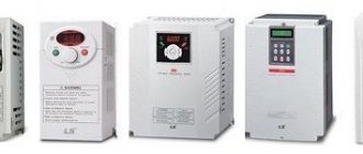
A real breakthrough in the field of adjustable electric drives was the emergence of power frequency converters or, as they are called in the specialized environment, frequency converters. This discovery radically changed the approach to the design of electric drive systems. If relatively recently, when designing complex mechanisms, where precise control of parameters (speed, torque) is indispensable, DC motors (DCT) were chosen, then with the advent of frequency drives, AC drives began to actively displace DC motors from these systems. Even in traction electric drives, an asynchronous motor with a squirrel-cage rotor displaces a series-excited DC motor.
Main components of the inverter: rectifier, DC link, inverter
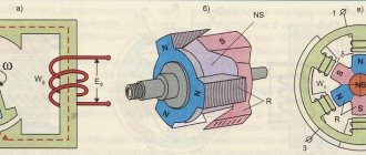
Rice. 1. Schematic diagram of the inverter
The rectifier is built using rectifier diodes or, less commonly, using a diode-thyristor circuit. Let's focus on the simplest - diode rectification.
Three-phase mains voltage with a frequency of 50 Hz and a voltage of 380 V is supplied to the input of the rectifier. After rectification, we get a pulsating voltage; it already has a certain kind of pulsation, but is not yet constant. The voltage becomes constant after the DC link enters and the ripples are smoothed out. Between the rectifier and the DC link there is a so-called precharge resistor.
Precharge resistor
limits the charging current of the capacitors at the first moment of time, thus protecting the rectifier diodes and the network from a large current surge. As the capacitor charges, this resistor turns off and does not take part in further operation.
DC link
As a rule, it is a set of capacitors of fairly large capacity. The task of this element is to smooth out voltage ripples as much as possible and bring it to a constant value. In a normal situation, when the mains AC voltage is 380 V, the value at the rectified DC link is 540 V. If the mains voltage is higher or lower, the value of the rectified voltage increases or decreases proportionally.
Basic circuit of a ramp voltage generator.
To understand the origin of the formation of a linearly increasing voltage, one must always remember how the transition process occurs in integration circuits. The potential across the capacitor will be determined by the amount of charge that is stored in the capacitor.
The size of the capacitance and the magnitude of the current are constant. Therefore, the charge voltage of the capacitor directly depends on the time that passes since the switch is closed. A capacitor has a potential, which is the sum of all voltages over time. This process is called integration, and the circuit for this operation is an integrator.
An integrator of this type, which has a non-constant potential shape at the output, becomes the basis for building triangular and saw-shape voltage generators.
Structure and features of the inventory
After the rectifier, the voltage is supplied to the inverter. The inverter is the most complex and important part of the frequency converter. From the output of the inverter, the signal goes directly to the electric motor. The voltage form at the inverter output is a set of rectangular pulses of different widths and a certain duration. This is how the power part of the frequency converter is built.
The device circuit also includes low-current circuits that help the interaction of all the main parts of the inverter. In particular, there is a central processor, which is, in essence, the brain of the converter and controls both the operation of the inverter and other parts of the device. The processor receives information about the output current from current sensors located on the output circuits of the inverter. The signal from the current sensors is processed, and the processor then generates a control algorithm so that the converter can operate under user-specified conditions. There is also a power supply for its own needs; it powers both the processor part and the part responsible for measuring the output current and measuring the voltage on the DC link. In addition, there is a block of driver chips, which in turn control the transistors of the inverter part, and a number of auxiliary elements.
Rice. 2. Schematic diagram of the inverter
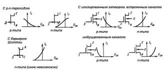
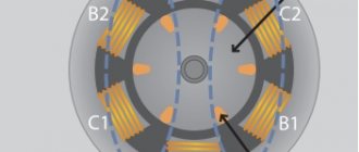
Let's consider the basic design of the inverter part. The main elements of the power part of the inverter are IGBT transistors - powerful, specially designed for operation in switching mode. This is a hybrid of field-effect and bipolar transistors. The control part is an insulated gate (like a field gate), and the power part replicates the bipolar device, which has a collector-emitter.
Power elements are produced in the form of a dual module, consisting of two power transistors connected in series. Each of the transistors is shunted by a diode in the opposite direction. Since the output must have 3 phases, the inverter design has 3 arms (see Figure 2).
Rice. 3. Equivalent circuit of transistors
To better understand the principle of operation, consider an equivalent circuit where each transistor is replaced by a conventional switch. The diagram (Fig. 3) shows 6 switches (transistors) and an electric motor.
Let's study how output currents are formed in the motor windings. The central processor is responsible for controlling the transistors (switches in the diagram). It switches them strictly according to a specific program, which is initially set by the algorithm of its action.
The diagram shows the operation of keys No. 1, No. 4, No. 6. Please note that it is strictly forbidden to have a situation where both the upper and lower keys are closed in one arm - this will result in a short circuit and failure of the product. In the situation shown in the diagram, current flows through open switch No. 1, then enters winding A of the electric motor, exits windings B and C, and through open lower keys No. 4 and No. 6 goes to the negative link.
In order to change the current in winding C, you need to switch the switches of the middle arm. The current will still flow through open switch No. 1, and will go through winding B and switch No. 6 to the negative arm. In this case, at the same time, through closed switch No. 3, the incoming current through winding C goes negative. By changing the position of the open and closed keys, you can change the current in the motor windings. If this is done according to a certain program, you will get a variable current, as when the engine is running from the mains, that is, there will be a smooth flow of one phase to another.
Rice. 4. Current flow in the inverter
Now, instead of a simplified circuit with switches, let's consider how current flows in a circuit of transistors using the example of a real inverter (Fig. 4). At its core, this process is no different from the key mode discussed earlier, except that we are dealing with a real motor, which, in principle, is an inductive load.
At the moment the key is closed, the inductance of the motor will not allow the current to stop instantly due to the phenomenon of self-induction. This residual current is extinguished by reverse diodes, which are connected to closed transistors (see Fig. 4), i.e. at the moment of turning off (closing) the transistors, the residual current flows through the freewheeling diodes, thus preventing voltage surges on the switch.
But since the transistor acts as a switch, it can either supply full voltage to the motor or not supply it at all. In practice, it is necessary to obtain a certain smooth voltage of a sinusoidal shape, variable both in magnitude and frequency, in order to be able to control the rotation speed of an asynchronous motor.
Active filters.
In electronics, a circuit is widely used for isolating a useful signal from input signals and reducing signal noise using filters.
Filters are divided into passive ones, which are made of capacitors, coils and resistors, and active ones, based on transistors and amplifiers.
A filter is a device that passes signals in a certain passband and delays them in other frequencies.
According to the type of AHF filters, they are divided into low-pass filters and high-pass filters, as well as band-pass and notch filters.
PWM operation algorithm
Next, let's look at how the output voltage is generated using the pulse width modulation (PWM) method. For example, let's take a certain hydraulic model that will help us understand what is happening.
Rice. 5. Hydraulic model
Let us imagine that there is a series of containers. Each has holes at the bottom. Using a certain device that produces droplets of water of certain sizes with a constant frequency, we begin to fill these vessels. It is clear that where the droplet size is small, the liquid level will be set at a low level, and the larger the droplet size, the higher the level of the liquid in the vessel will be. By choosing the droplet size in a certain way, you can obtain the envelope of these levels (see Fig. 5). Thus, it was possible to depict a static picture, which gives an understanding of the process, how it is possible to make something similar to analog ones from discrete parts.
Now let's move on to working in dynamics. Let's imagine that there is only one vessel, but we change the size of the droplets with which it is filled. At the bottom of Fig. Figure 5 shows the process at this moment in time - along the x-axis time (t), along the y-axis voltage (U) or, in other words, the water level in the vessel. As the droplet size changes, so does the average liquid level, rising and then beginning to fall. This is already a dynamic process. Now we draw an analogy with electricity.
Figure 6. Converting a discrete signal to an analog signal
In Fig. Figure 6 clearly shows what happens to a discrete signal if we open the switch and close it at a certain frequency and for a certain time: the wider the transistor opening pulse, the higher the average voltage level (red signal envelope).
Let's introduce a few parameters and explain them.
- The period of a PWM signal is the time between pulses. The parameter is strictly specified and does not change (from the previously described example, this is when the droplets all drip with the same frequency, only of different sizes).
- The PWM modulation frequency is inversely proportional to the duration of the period; this is what we have as one of the parameters when programming a frequency converter. Determines the pulse repetition rate at the output of each channel of the IGBT module.
- Pulse duration (t-pulse). It is determined by the processor itself. That is, the processor, depending on the specified value of the output signal, currently determines for how long each key needs to be opened. If we consider the total period of change of these oscillations, we will have a period of the output frequency (t-output). This is the output frequency that we will have at the output of the frequency converter. The engine rotation speed directly depends on it.
The frequency converter ensures that the motor is not overloaded and the voltage supplied to it at this frequency is proportionally decreased or increased. He himself determines the required opening time for each key, that is, by determining the t-pulse. And this situation occurs simultaneously on three channels leading to the output of the converter to the electric motor.
It can be seen from the figure that the more often the pulses occur, the closer the voltage shape will be to sinusoidal.
CNC design
The large current reserve of the transistor modules embedded in the CNC, as well as the bus mounting and performance of the water cooling cabinet, make it possible, if necessary, to significantly increase the output power of the converter.
As shown in Fig. 7, fast-acting fuses are included on all nine inputs, protecting the NFC from incorrect switching in the event of failures in the control system; all control contacts of the fuses are connected in one circuit and are polled by the microcontroller.
Four transistor modules that make up one arm of the NFC are mounted on one cooler (block). In total, the NPC has nine separate blocks, and each of them also houses snubber capacitors, drivers and cooler temperature sensors.
To reduce the distortion factor of the output voltages, a lightweight LC output filter is applied.
All nine NFC units can be removed from the cabinet; you just need to disconnect all fiber optic connectors and water cooling hoses.
To connect the cooler to the liquid circuit, quick-release fittings and couplings of the CBI type from Staubli are used. This technology allows, if necessary, to disconnect the unit from the liquid circuit without leaks.
The appearance of the NPC cabinet is shown in Fig. 18, and the appearance of the control panel is shown in Fig. 19.
Rice. 18. Appearance of the CNC and water cooling cabinet
Rice. 19. NPC control panel
The operator panel displays a simplified mimic diagram of the CNC, displaying the states of the keys and some sensors. Virtual buttons are implemented on the resistive screen. On the right there is a built-in control oscilloscope, on which you can display the voltages and currents of the VFC selected by the switch. The signals are taken from the ADC inputs.
Coolant is supplied to the NFC units from the water cooling cabinet.
The hydraulic circuit of the cooling cabinet includes two circuits:
- external, at the inlet of which a pressure gauge, dirt filter, heat exchanger, and flow meter are installed;
- an internal clean circuit with distilled (deionized) water, in which, after the NFC blocks, a water temperature sensor, a dirt filter, a heat exchanger, two branches with pumps (duplicated for reliability) and check valves, a flow meter, a pressure gauge and a temperature sensor for the water supplied to the converter are installed.
When choosing a heat exchanger, it was decided to choose products from the largest manufacturer of heat exchange equipment in Russia.
Since the system has significant differences in the cross-sections of the water channels, i.e., there is a high probability of cavitation occurring at the expansions, it was decided to keep the entire internal circuit under pressure. For this purpose, a membrane expansion tank InterVarem 20 with a capacity of 20 liters is built into the system, in which a pressure of 1.5 bar is maintained.
The selected Grundfos CRN pumps are known to have high performance, so to regulate the flow in the internal circuit, a reliable small-sized frequency converter FR-D700 from Mitsubishi with a power of 3.7 kW was used. The use of a controlled flow allows you to avoid water hammer in the system and save water in the external circuit. Rittal constructs were chosen as shells for the cabinets.
Frequency selection criteria
In practice, the PWM frequency can be set by the user, usually in the range from 1 to 15 kilohertz. In order to obtain a voltage more or less close to a sinusoidal shape, the PWM frequency should be 20-30 times the maximum output frequency that you want to obtain.
You can choose the PWM frequency arbitrarily for your specific task. There are several parameters that determine the choice.
Fig.7. Parameters influencing the choice of PWM frequency
1. Cable length to motor. The longer the cable, the lower the PWM frequency can be set. For example, if your cable length is 100 meters or more, then there is no point in setting the PWM frequency to more than 2.3 kilohertz, otherwise there will be large losses and wasted power at this length.
2. Acoustic engine noise. When the motor is powered by a frequency converter, extraneous noise is heard. It depends exactly on the PWM frequency that you set. The higher it is, the higher the pitch of the sound. If the purity is set to more than 8.10 kilohertz, the noise is practically inaudible. At lower frequencies (1.3.5 kilohertz) this noise is significant and causes discomfort.
3. Maximum output frequency. Most motors use a maximum inverter output frequency of 50Hz, so here the PWM frequency must be at least 20 times higher. Here you can set the frequency of 1, 2, 3, 5 kilohertz from the entire range.
If you are using a high-speed motor, for example a 400-Hz motor, then you should not set the PWM frequency to 1.3.5 kilohertz: the output will not be a sinusoid. For such high-speed motors, the PWM frequency is selected as high as possible for a given inverter, say, 15 kilohertz.
4. Heat generation from the inverter part of the converter. This is due to the fact that the IGBT transistors that generate the output voltage are not ideal and are subject to heating during operation. In order to effectively remove heat, it is necessary to use appropriate radiators and cooling fans. The greater the heat generation in this inverter part, the more powerful cooling devices must be used.
Energy losses in a frequency converter and ways to reduce them
Let's consider the issue of heat generation in the inverter part of the converter. What determines the losses of a transistor?
Fig.8. Energy loss
Let's take a conventional IGBT transistor, which is connected to a circuit with a voltage of 500 volts, limiting the resistor.
Closed state: there is no voltage at the gate, the voltage at the collector is equal to the mains voltage, there is no current, leakage is negligible, and there is no heat generation. We open the transistor using a voltage of 10 volts at the gate, this is the standard voltage for almost all transistor modules. The transistor does not switch to the open state instantly; each transistor has a parameter called on time or off time. A typical value for the most common transistors is 0.2 microseconds. The time is short, but during this time there is both a voltage on the transistor crystal, which quickly drops, and an increasing current value, which also does not increase instantly. At this point, losses occur. And the higher the PWM frequency, which we talked about earlier, the more often the transistor turns on and off, the more heat is generated due to switching losses.
When the transistor has opened, a static mode has been established for some short time, heat generation continues: it occurs due to the fact that at the moment of the opening state, the voltage on the transistor is also not zero, it is determined by losses on the crystal in the open state. Its typical value is 1.5 volts. It may vary slightly depending on the manufacturing technology of the transistor, etc.
At this moment, heat generation also exists, but we cannot do anything about the losses in the on-state, the maximum is to use transistors with a lower voltage in the on-state. We can combat switching losses by reducing the PWM frequency. This is useful if the inverter is located in a closed cabinet, where it gets hotter. By lowering the PWM frequency, we can reduce losses on the converter and reduce its temperature.
The total loss of the frequency converter in the form of heat is about 3%.
Rectifier losses occur through open diodes. The voltage drop across the open diode, as well as the rectified current flowing through it, lead to its heating. The DC link, consisting of large-capacity electrolytic capacitors, also heats up because the charge and discharge process is constantly occurring. Losses also include the frequency converter’s own needs: the operation of cooling fans, electronic circuits, secondary power sources, and so on.
Saw-shaped voltage generator.
The above-described converter must be quickly converted into a sawtooth potential generating device. You just need to make a different frequency of charging and discharging the capacity according to the circuit of the summing element. The changes will concern the charge-discharge circuit of the capacitor in the integrator. Diodes will make it possible to charge and discharge the capacitor with different currents. All other actions of the generator are similar to the previous one. Its design is asymmetrical. The frequency at the output of this sawtooth potential is the sum of two resistors. Temperature instability limits the stability of the current frequency.