A cozy and comfortable life now means not only a full refrigerator or cellar of food, but also the warmth of the living environment, its lighting, the availability of accessible water and the convenience of using basic things. For example, lighting a fire for cooking purposes. Everything mentioned is currently provided by energy carriers - hot water in radiators, electricity, gas fuel in water heaters and stoves.
The extraction of these elements and their delivery to the end consumer, in the life of the average person, is entrusted to third-party organizations. The latter automatically sets a price for the energy carrier, which is directly related to the maintenance of the transport structure and not the final cost of initially obtaining the resource.
The decision on the amount of one or another supply element spent is assigned to various meters, which, depending on the volume of consumption of electricity, heat, water or gas, record consumption. Subsequently, this information becomes the basis for invoices presented to the end consumer.
The body of the article will discuss the operating principle of the electric meter, as the most common metering device. It is used in almost all human living spaces, determining the energy expended by household appliances, lighting or industrial equipment.
Varieties
Various counters:
There are many gradations by which electricity metering devices are distinguished. Among them:
- Which line is the device designed for - single or three-phase?
- The internal mechanism is induction or completely electronic.
- The method of connecting to the load is direct or through a current transformer.
- Accuracy class.
- Accounting for one or more tariffs.
- Functionality for taking readings - only direct or combined with remote. This also includes the ability to control the operation of the device from a separate control panel.
A less important difference between electric meters, but used in some documents, is the power consumption of the meter itself. It also consumes a certain amount of energy necessary for its operation.
However, the fundamental difference should be considered the design features - an induction-type electric meter or a completely electronic one. The accuracy class of the device, its functionality and the number of tariffs taken into account depend on this factor.
Induction meter “from the inside”:
In essence, induction meters are simple, cheap and reliable. Their basis is mechanics and electrical. Unfortunately, this factor also introduces certain restrictions on the capabilities of the device. For example, without greatly complicating the design, it is impossible to obtain large service functions from the device.
Electronic ones are structurally more complex and can perform many additional actions, such as sending readings remotely, disconnecting the consumption line from a remote control located far from the device, maintaining several electricity price tariffs depending on the time of day. In addition, they have greater accuracy, unlike the previous version of the meter. And one more factor that electronic meters are certainly good for is the possibility of retrospective. Its essence is to store evidence for several reporting periods. And this information is easily accessible from a specific device.
Energy consumption depending on the time of day:
The basis of a digital electricity meter is a completely electronic circuit, without moving mechanical elements. It contains several microcircuits, current transformers and a miniature computer that controls all of the listed equipment. The latter is called a microcontroller. Everything is mounted on a single board at the factory, which eliminates damage to the connections of the elements during operation.
Software
The software for three-phase electricity meters of the Pulsar brand includes:
- internal software - the integrated memory of the equipment is programmed at the stage of its production;
- external software - the ElectroMeterConfig.exe software module is installed on external equipment (PC, laptop) to configure and verify electricity meters.
The level of software protection against unauthorized data correction complies with the standard R 50.2.077–2014 and is defined as “medium”.
What does the meter take into account?
Regardless of how the electric meter is designed, it basically measures the power of the consumer, depending on which the amount of energy expended is calculated for a specific period of time. The resistance (load) indicator itself in AC networks can be active or reactive. And at the root of the sum of the squares of the values of both types of consumption (formula - P = √ ((UI cosθ)2+ (UI sinθ)2) it gives the total load power of the circuit. The difference in the indicators is that with active power some work is performed, and with reactive energy, energy circulates in vain between connected network elements.The last factor arises in cases where a capacitor or transformer coil is connected to the alternating current circuits.
Because of their design, induction meters are capable of detecting either active load or only reactive load, which was used by some unscrupulous consumers to distort readings in metering devices of older models. Electronic ones operate on both characteristics, calculating the total power using a special formula, using the current network load characteristics as a basis.
Functionality
In addition to measuring energy consumption, Pulsar three-phase meters demonstrate a number of additional functionality:
- measurement of power quality indicators (based on deviations from the norm of voltage and frequency);
- measurement of electrical network characteristics (active, reactive, apparent power, power factor, current, voltage, network frequency);
- maintaining hourly, daily, monthly archives;
- Event logging.
The readings are displayed on a liquid crystal display and can be transmitted to a central server via a digital communication channel. Indicators of power, power quality, as well as the event log can only be read using a digital communication channel.
Induction meters
Internal structure of an induction meter:
The basis for the functionality of these meters is the physical law of magnetic induction. In the design, to create the effect, two electromagnets of different shapes and orientations relative to each other are used for each phase of the consumer. One of them is connected directly to the mains power, and the second to the load line break. The fields they generate initiate the appearance of eddy currents on a disk of conductive metal, due to which the latter is set in motion, making revolutions around its axis. Moreover, the stronger the load on the line to which one of the field generators is connected, the more electrons accumulate on the moving element, which is why it rotates faster. In order to limit the moment of movement - so that the speed does not become equal to that used in the electric motor - a permanent magnet installed near the surface of the aluminum disk is used.
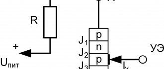
Classic scheme:
The above image shows the magnetic fields circulating during the operation of the device. They are designated ФI, ФU1 and ФU2. The remaining elements of the diagram are indicated by numbers. Under number 1 with a winding marked 2 is the guidance electromagnet. The armature of the second is marked 3 with power line 4 connected to the load. An aluminum conductive disk is attached to 6, and 7 is the axis on which it is located. 8 - gearbox that transmits torque to the counting mechanism 9.
The design of an electric meter of a similar design is so simple that induction electricity meters were manufactured and used back in the 19th century.
Electronic meters
For the most part, electronic meters do not contain moving mechanical parts. The exception is some types of displays, the readings of which change due to the operation of a stepper motor driving the corresponding gears of the internal gearbox [Yu.P.1].
Mechanical scoreboard:
Hybrid versions of metering devices were developed and even entered the market, containing additional functionality integrated with a conventional induction meter. We are talking about communication, storage and remote control systems. They did not take root due to the too high complexity of the work, leading to a decrease in the overall reliability of the device.
A simpler option was to manufacture the entire meter using electronic components, which include a “smart” control part in the form of a microcontroller. The latter not only performs the above functions, but also provides many additional features. For example, it calculates the total load power using incoming data on active and reactive current consumption from the corresponding sensors.
Block diagram of the internal structure of an electronic meter:
For each phase, its own combination of current and voltage transformers with sensors is used, the readings of which are sent to the input of the analog-to-digital converter microcircuit, from where they are sent to the microcontroller in the form of code sequences. In turn, it calculates the current expended, displaying the result in kilowatt-hours. The received values are sent further - to the display device and communication system (if available). The calculated information is also permanently stored in non-volatile memory. Moreover, during certain periods specified by the settings, the microcontroller places the total accumulated consumption in separate cells, which allows you to obtain a graph of load power for certain periods of time.
Also, the “smart” part of the metering device is responsible for controlling the line leading to the final client devices of the electronic electricity meter. He can, by remote or direct command, turn off consumers or perform actions in the context of power limitation conditions. That is, when the consumption on the line exceeds the established limit. This functionality is provided by a relay directly connected to the microcontroller that controls the break in the power line of client devices.
Internals of the electronic meter:
The electrical meter circuit in a simplified version, presented in the device from Texas Instruments, looks like this:
All the main elements are visible on it, including a current transformer, a digital display and the mandatory clock generator needed by all types of microcontrollers. It is the latter that sets the operating speed and reaction time of the logical part.
In essence, any existing electronic electricity meter is built on the same elements that are indicated in the given device. Of course, with the condition that different manufacturers will have a different elementary base and some components may be added that expand the final functionality.
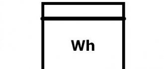
How does an electric meter work?
The device of a single-phase direct-connection electric meter, Energomer, will now be clearly visible in the photographs. Let me remind you that his appearance is in the first photo of the article.
I got a working meter, they gave it to me because where it stood, the owner of the premises changed, and the new owner was obliged to change the meter.
There are usually 2 seals on the meter, one protects the meter terminals from unauthorized access, the second protects the electronic circuit of the meter. These seals are no longer on my meter.
Let's take a closer look at the terminals.
The terminals are clamping and hold the stripped wire well along its entire length.
Now the most interesting thing is to open the meter housing:
Energy meter tse6807p. Front panel removed
Energy meter counter. Removed cover, photo 2
We take out the guts and see that the electric meter circuit consists of three main parts:
This is 1) a stepper motor with numbers attached to its axis, 2) a board with a controller and 3) input terminals. As you can see, everything is Chinese (I hope, except for the terminals), which is why the price of such a meter is 650-750 rubles.
By the way, I haven’t seen it, but in Mercury the production of components is Russian. Who will confirm?
Terminals and board with controller. Everything is upside down, so the phase terminals of the meter are on the right, zero terminals are on the left, not as we are used to seeing.
The white and green wires are the output of the measuring shunt. The same shunt on which the voltage, proportional to the current through the phase terminals, “settles”. This voltage is supplied to the inputs of the board KT1 and KT2 and is supplied to the controller for processing.
Also, power for the controller is taken from the phase terminal; this is the yellow wire. Power supply is transformerless, through a capacitor, rectifier and 5VDC stabilizer.
The zero terminal is used to take the second pole to power the meter. And also in order to ensure connection, and to limit malicious schemes for turning on the meter.
From the output of the controller board through points M1.1 and M1.2, pulses are sent to the stepper motor. The one that is braked using a magnet. The pulse frequency is proportional to the current, and is additionally indicated by an LED.
I talk about the stepper motor on my blog in an article about.
This LED is used to check and verify the meter. Count the number of pulses in (for example) 5 minutes, and look at the correctness of the readings on the front panel.
The controller contains a program that generates pulses for the operation of the stepper motor.
By the way, the program can be changed, craftsmen do it. This way you can reduce the meter readings by 30 - 50%.
Here is a slightly larger photo of the meter printed circuit board:
Advantages and disadvantages of specific types of metering devices
The main advantage of pulse metering devices: their simplicity, reliability and low price. That's where the advantages end. The mechanics are initially subject to external influences and do not provide the required level of accuracy. Not to mention the functional volume. The most important of the latter is the lack of automatic data transfer to the energy supplier operator. The direct participation of people in the procedure of taking readings, disabling or activating the device is required.
Taking readings by housing and communal services workers:
An electronic meter does not have such problems. There are no moving parts, the layout is more complex, there are internal logical elements. All of the above allows you to monitor the operation of the meter remotely, receiving information about current readings online and control the supply of energy to consumers. The last two functions are needed not only by management companies, but also allow the metering device to be integrated into a smart home system in order to provide information to the consumer. Which, in turn, can, for example, provided that the necessary software is available, not only monitor the situation in general, but also pay bills automatically.
In addition to the above-mentioned advantages, we can also remember that the physical principles underlying the way meters of a similar design work will not allow the distortion of incoming data from consumption devices by methods used in relation to pulse metering devices.
Digital meters also have disadvantages. In essence, the failure of any of the circuit elements will lead to its complete inoperability, which is quite important due to the low quality of the parts used. In practice, the service life of an electronic meter is lower than that of an induction meter.
Reliability of readings and need for repairs
A high-quality digital electricity meter is highly accurate. You can check the parameters without violating the integrity of the case and seals as follows:
- After the power supply is stopped, the indicator stops. If recording continues, the device is faulty.
- The meter always buzzes during operation; a problem is indicated by the self-propelled machine.
- The readings are distorted when all household appliances are turned off. The presence of a self-propelled vehicle must be checked.
Testing is best done at night, under conditions of minimal load on the power grid. If there is no self-propelled gun, there are no indicator pulses for 15 minutes. A pulse that occurs when the connection is not made means a breakdown.
Only employees of the energy saving company should repair the digital meter. The user contacts the authority to obtain permission to check and replace the device.
Connecting an electricity meter
Having considered the functional principles of the electronic meter, it’s time to move on to the practical part. We will talk about how to properly install a single- and three-phase meter.
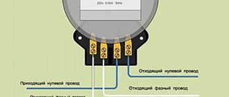
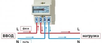
The installation diagram for an existing power grid is directly indicated on the device body or its documentation. It is different for 220 V and 380 V networks (one or three phases, respectively). In general, an electric meter, regardless of its type (electronic or induction), if it is designed to operate on one phase, is connected according to the following diagram:
Installation of a three-phase electricity meter is performed a little differently:
The sequence of contacts may differ for different models.
In addition, there are special cases when the electric meter is connected to the line not directly, but through current transformers:
After installing the metering device (unless, of course, it is done in the interests of personal information), you need to contact the service personnel of the organization supplying electricity. The latter will check the correct connection, take the initial readings of the device and record its factory data. Afterwards, the metering device must be sealed in order to prevent subsequent changes to the connection diagram.
Selection criteria
One of the criteria for choosing an electric meter is the number of tariffs.
Before purchasing a device, you should pay attention to a number of parameters:
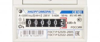
- Permissible current value. Digital models are designed for current 5-60A, which is suitable for apartments and private houses.
- Date of inspection. The three-phase meter must have a seal no older than 1 year.
- Number of fillings. The first sealing is done by government agencies - a mark is placed on the casing. The second seal on the clamp cover is from the power supply company.
- Optional. The more functions, the more expensive the meter. But the internal rater creates a load graph, and the event log notes the increase and decrease in voltage in each phase.
- Service and guarantees. High-quality models have a long warranty period. The brand's service center is located in the buyer's city.
- Check interval. Optimally – from 10 to 16 years.
- Integration with ASKUE. The readings are automatically transmitted to the provider.
- Phasing. The information is indicated on the board. A single-phase device is marked 220 or 230 V, three-phase - 220/380 V or 230/400 V.
- Number of tariffs. The two-tariff scheme eliminates overpayments for electricity at night.
- Installation method. The digital device is mounted on screws (S or W housing) or DIN rails (R or P housing).
The seller is obliged to stamp the device and record its starting readings.
Notes on accuracy class
Previously, the accuracy class of the electric meter was mentioned. It is usually indicated on the device body and determines how sensitive the latter is to the consumption line. The lower the value, the more accurate its readings are, even at low loads. This is both a plus and a minus of the metering device. For regulatory organizations, the more sensitive the device, the more income. The opposite is true for consumers. No one wants the meter to evaluate a TV, microwave, washing machine or refrigerator that is in standby mode when it is not doing anything active and is only using a “drop” of electricity.
At the bottom left of the display, in the circle, is the accuracy class of the device:
From a practical point of view, it is impossible to install metering devices below the second accuracy class. But such sensitivity is ideal for household purposes. In the case of organizations, it is better to use a first class counter.
Installation diagram
When designing a modern electrical network, the first thing to do is make it safe. For this reason, a switch is placed in front of the meter in the form of a switch or circuit breaker.
With a gun
A good option is a two-pole circuit breaker that protects wiring and household appliances from overloads. If the voltage exceeds the permissible limits, the machine will automatically turn off the power. First, wires (coming from the pole) are output to the machine, and from it they go to the meter. The distance from the machine to the electric meter should not be more than 10 meters.
You might be interested in Nikola Tesla Electric Generator
Connection with machine
With automatic machine and fire protection RCD
The machine will protect equipment from overload, but will not respond to insulation breakdown or human touch to a working wire. The residual current device (RCD) is responsible for this. To protect all wiring, a common RCD is installed.
Installation location: after the meter. The set leakage current is not less than 100 mA. It is not for nothing that the device is called a fire-fighting device, since it de-energizes the network during strong leakage currents, which can lead to sparking and fire. A zero and a phase are connected to the RCD. From the output of the RCD, the phase is supplied to the machine, the neutral - to the bus. Zero is already supplied from this bus.
With RCD