The ATS circuit for two inputs from transformer substations with sectioning is built on the basis of automatic switches with motor drives that ensure automatic switching of inputs. The EKF PRO-Relay programmable relay is used as a logical device that controls the operation of the circuit.
In addition to these devices, the operation of the circuit involves phase control relays for monitoring phase voltages, symmetry and phase sequence, automatic power supply circuits for the control circuits of the ATS circuit and motor drives, an intermediate relay through which the power supply for the control circuits is switched from either the first or the second input, depending on the presence of voltage on one of them.
Circuit breakers are equipped with status contacts for position signaling and emergency contacts.
The circuit also includes a switch for selecting manual/automatic operating modes, an ATS error reset button, and lamps to indicate the operation of the circuit.
Sectional switch purpose
Let's consider the principle of operation of ATS circuits using the example of a two-transformer substation shown in Fig.
3.2. Normally, both transformers T1 and T2 are turned on and supply the consumers of the low voltage bus sections. Rice. 3.2. (see scan) Diagram of automatic transfer switch of a sectional switch at a substation: a - diagram of primary connections; b - alternating voltage circuits; c - operational current circuits
When switch Q1 of transformer 77 is turned off for any reason, its auxiliary contact SQL2 opens the circuit of the intermediate relay winding KL1. As a result, the armature of relay KL1, pulled up when the switch is in the on position, drops off after a certain time delay when the voltage is removed and opens the contacts.
The second auxiliary contact SQ1.3 of switch Q1, having closed, supplies a plus through the still closed contact KL1.1 to the winding of the intermediate relay KL2, which with its contacts turns on the sectional switch Q5, acting on the switching contactor YAC.5. After the set time delay has expired, relay KL1 opens the contacts and breaks the winding circuit of the intermediate relay KL2. If sectional switch Q5 is turned on by the action of the ATS circuit on an unresolved short circuit and is turned off by relay protection, then it will not be turned on again. Thus, relay KL1 provides one-time operation of the ATS and is therefore called a one-time switching relay. Relay KL1 will close its contacts again and prepare the ATS circuit for a new action only after the normal power supply circuit of the substation is restored and the QL switch is turned on. The time delay for opening the KL1 contact must be greater than the switching time of the Q5 switch in order for them to turn on reliably.
In order to provide ATS, when switch Q2 is disconnected, a command is sent from its auxiliary contact SQ2.2 to the trip coil YAT1 of switch Q1. After Q1 is turned off, the ATS circuit starts and operates as discussed above.
Similar to the sectional switch discussed above, the automatic transfer switch will operate when transformer 72 is turned off.
In addition to the considered cases of disconnecting one of the transformers, consumers will also lose power if for some reason they are left without voltage from the high voltage bus B (or A). The ATS circuit will not work in this case, since both switches T1 (Q1 and Q2) or T2 ( Q3 and Q4) will remain switched on. In order to ensure the operation of the ATS circuit in this case, a special minimum voltage starting element is provided, which includes relays KV1, KV2 and KV3. When the voltage disappears on the buses of substation B, and consequently on the buses B, the minimum voltage relays connected to the voltage transformer TV1 will close their contacts and supply a plus operating current to the winding of the time relay CT through the relay contact KV3. The KT relay will then start and, after the set time delay has elapsed, will supply a plus to the winding of the output intermediate relay KL3, which will turn off the switches Q1 and Q2 of transformer T1. After switching off switch Q1, the ATS circuit will operate as discussed above.
The KV3 voltage relay is designed to prevent the disconnection of transformer T1 from the minimum voltage starting element in the event of a lack of voltage on the high voltage buses A of the backup transformer, when the operation of the ATS circuit will be obviously useless. Relay KV3, connected to voltage transformer TV2 of buses A, in the absence of voltage, opens contact KV3.1 and breaks the circuit from contacts KV1.1 and KV2.1 to the winding of the time relay CT.
A similar minimum voltage starting element is provided to turn off transformer T2 in the event of a loss of voltage on buses A (not shown in Fig. 3.2).
In Fig. Figure 3.3 shows an ATS diagram on alternating operating current for a sectional switch of a substation with two transformers powered without switches on the high voltage side from two lines. Section switch Q3 is normally open. The operational current to power the automation circuit is supplied from auxiliary transformers T3 and T4. A special feature of the circuit is that when the voltage on one of the lines (W1 or W2) disappears, the ATS device turns on the section switch Q3, and when the voltage on the line is restored, it automatically restores the normal substation circuit.
The starting element of the automation circuit is time relays KT1 and KT2 of type RV-03 (EV-235), the contacts of which KT1.2 and KT2.2 are connected in series in the YAT1 circuit. In series with the contacts of these relays, an instantaneous contact of the time relay KT3.1 of transformer T2 is connected, which controls the presence of voltage on this transformer. The relay windings KT1 and KT2 are connected to different transformers (T3 and TV1), which eliminates the possibility of false action of the trigger in the event of a fault in the voltage circuits. Relay KT1, connected to the auxiliary transformer TZ, installed before the transformer switch T1, is also used to monitor the appearance of voltage on T1 when line W1 is turned on.
When the voltage disappears as a result of disconnecting line W1, time relays KT1 and KT2 will start and their instantaneous contacts KT1.1 and KT2.1 will open, removing the voltage from the winding of time relay KT3 type RV-01 (EV-248). This relay, when voltage is removed from its winding, instantly returns to its original position, and when voltage is applied, it operates with a set time delay.
If the action of the automatic reclosure circuit of the line does not restore the voltage at the substation, then with a set time delay (longer than the time of the automatic reclosure of the line), the contacts of the time relays KTL2 and KT2,2 are closed, recording the lack of voltage in the 1st section, and create a circuit to the trip coil YAT1 of the circuit breaker Q1 of transformer T1 with voltage control on the 2nd section (contact KT3.1). When switch 01 is turned off, its auxiliary contact SQL1 (Fig. 3.3, c) will close in the circuit of the switching coil YAC3 of the sectional switch Q3 through the still closed contact KQCl. 1 one-time switching relay. The section switch will turn on and supply voltage to the substation section, while the time relay KT2 will pull up, close contact KT2.1 and open KT2.2. Relay KT1 will remain without voltage, so its contact KT1.1 will remain open, and time relay KT3 will still be in its original position, keeping all its contacts open.
Rice. 3.3. (see scan) ATS diagrams of a sectional switch on alternating operating current for a substation with two transformers connected to power lines without switches: a - substation diagram; b - control circuits and ATS of switch Q1; c - control circuits and ATS of switch Q3 (circuits related to transformer T2 are circled in dotted lines); d — acceleration circuits of protection Q3
When the voltage on line W1 is restored, voltage will also appear on transformer T1, since its separator remained on. Having received voltage, relay KT1 will pull up, close contact KTL1 and open contact KT1.2. When contact KT1.1 is closed, the time relay KT3 will begin to operate, which, with its sliding contact KTZ.2, will create a circuit to turn on switch Q1, and with the end contact KT3.3 - a circuit to turn off the sectional switch, and the original substation circuit will be automatically restored. In the considered case of a sectional switch, the shutdown circuit is created only if switch Q2 of transformer T2 is turned on. If switching on switch Q3 is unsuccessful due to the presence of permanent damage in the 1st section, it must be taken out for repair. An automation circuit similar to that shown in Fig. 3.3, ensures the operation of the ATS when transformer T2 is turned off.
For quick shutdown in the event of switching on switch Q3 on K3, the circuit provides for acceleration of protection of the sectional switch after the ATS. Acceleration is carried out by relay contacts KQC1 and KQC2, which bypass the contact of the sectional switch protection time relay.
Varieties
High-speed switches have a special mechanism that turns off the network. Based on the principle of operation of this element, they can be divided into two categories. The first category is devices with a spring shutdown option, where circuit breaking is achieved due to the force of powerful shutdown springs. The second category is magnetic spring devices. They also use spring force, but add an electromagnetic force to disconnect the circuit.
In addition, there is one more point on which high-speed switches are divided into categories - the ability to respond to the direction of current.
In this case, polarized and non-polarized devices are distinguished. The first type is capable of breaking the circuit provided that the current flows in a certain direction. The second type will open the circuit when a certain current value is reached, without paying attention to the direction in which it flows directly through the device.
It is worth noting that previously domestic high-speed circuit breakers were produced, which were widely popular at traction substations. It is worth adding here that the production of some models of this equipment has already been completed, but they are still in operation.
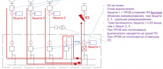
Protection and automation of sectional switch 6(10) kV
For a sectional switch (CB), the protection is almost identical to the 6(10) kV input protection. It must be remembered that the connection signals of both sections converge in the CB.
For example, if we talk about breaker failure, then breaker failure signals from each connection of the substation are input to the CB, while only the breaker failure of connections of its section is input. The same goes for LZSh and arc protection signals.
SV 6(10) kV is a kind of node where many protective signals are brought together. Therefore, the CB terminal must have enough discrete inputs.
For networks with one-way power supply (and we are considering just such), the CB is always turned off in normal mode. If the ATS is triggered, it first turns off the input that has lost power, and then turns on the SV. It may be the other way around, but this is more typical for high-speed AVR (BAVR), which is gaining popularity today.
There is no ATS algorithm in the SV terminal as such. It simply executes commands from the ATS input terminals, which control the CB through discrete inputs.
We can say that the relay protection and protection of a sectional switch for a standard circuit is quite simple and usually does not raise questions even for novice specialists.
By the way, a question for beginners: why don’t they use a current cutoff at 6(10) kV SV? After all, the short-circuit current on the busbars is maximum and it should be turned off as quickly as possible. Write your answers in the comments.
Next time we’ll look at the protection and automation of 6(10) kV TN
BEMP RU-SV contains all the protections listed in the article
Cutoffs are not used on the CB, because it is unlikely to be able to adjust it in terms of current from the cutoffs of outgoing lines, as well as maintain the sensitivity coefficient at the end of the protection zone, i.e. in front of the outgoing line, unless of course the busbars are made of some kind of steel)) LZSh helps to quickly turn off damage to the busbars. In networks with a voltage of 35 kV, an accelerating cutoff on the CB is sometimes used, but perhaps this is only in old schemes and in networks of 6 (10) kV it is not used at all
The cutoff is not adjusted from other cutoffs. It is tuned mainly from magnetizing current surges and maximum short-circuit current at the end of the zone. And for the CB, the zone has zero length (buses), so the short-circuit currents at the beginning and end of the zone are the same. Thus, the cutoff simply cannot be chosen. And in general the answer is correct
It turns out that only the MTZ is adjusted according to current. Although it is logical, the protection zone of the overcurrent protection of one connection overlaps the area of the overcurrent protection of another, and for reliability, the operation current of one overcurrent protection is adjusted from the other, with a cutoff this is not even possible, thank you)
The selectivity of the MTZ is ensured by a time delay. In terms of current, the overcurrent protection of adjacent sections is consistent in sensitivity so that the higher-level protection does not start up without starting the lower-level one. If this topic is interesting, then I suggest watching the MTZ Course - https://pro-rza.ru/kursy/videokurs-2-maksimalnaya-tokovaya-zashhi/
I agree with Alexander, TO by its nature will not work selectively in relation to outgoing feeders, in order to make it selective, you need to either increase the operating current (reduce sensitivity) or make a time delay (deprive the speed), so the question arises “Why is it needed ?. LZSh and DgZ will cope with the task faster and more reliably.
Internet forums are an extremely harmful thing! The question is posed incorrectly. First you need to understand in what mode the network operates. 1. For example, when a substation operates from two inputs and the sectional switch is closed, a short circuit occurs in one of the sections. In this case, we divide the buses with a sectional switch without a time delay (to reduce short-circuit currents), and only then figure out which bus is short-circuited. 2. On generator voltage busbars - everything is the same! 3. For example, during a short circuit at a connection connected to the busbars, the main set of relay protection and protection devices together with the breaker failure fails and the damaged section of the network will be disconnected by subsequent protection. Blocking the local ATS from subsequent protection is impossible due to its remoteness. When the voltage on the busbars decreases, the local ATS will be started by the sectional switch on the short circuit. When the SV is turned on, the acceleration of the sensitive protection of the SV and the MTZ will always work in 0.15..0.2 s. That is, with a minimum time delay required to detune from surges of the magnetizing current of transformers and the surge of the aperiodic component of starting currents of electric motors. But the cutoff in this case should work without a time delay. Because in this case there is no difference: we have a short circuit on the buses, or an undisconnected short circuit behind the switch at the connection. Sincerely, A.L. Solovyov
Alexander Leonidovich, good afternoon. I considered a standard 6-10 kV distribution substation with basic connections - this is in the first article of the series on 6-10 kV protection (https://pro-rza.ru/zashhity-tipovyh-prisoedinenij-6-10-kv/) . Of course, the operating modes of the SV may be different, but we are considering the main case when the SV is open in normal mode. There are very few ring modes through SVs in the distribution network; today, parallel operation of transformers is almost never provided for (the networks themselves are against it). It’s really better to separate the station buses right away to reduce the impact on the generators, but that’s another topic.
As for question 3, you have some kind of strange circuit, where there is a CB, but there are no input switches. A short circuit on a line where the relay protection kit has failed must be turned off by input protection, and not by remote connection protection. In this case, the ATS will be blocked in normal mode and the SV will not turn on. If instead of switches you have VNAs at the inputs, then you cannot do a 6 (10) kV ATS, exactly for the reasons that you described (there is no way to block the ATS during a short circuit). In this case, the ATS can be made 0.4 kV lower.
1. Firstly, no one has canceled the parallel operation of transformers. Indeed, it is not used often, but it is used in modes with large differences in transformer loads. 2. It’s good that you agree about the generator voltage buses. 3. Listeners came to me who had in their circuits: there is a CB, there is an AVR, there is a breaker failure at the VNA inputs, and the input line switch is located 300 meters away.
That’s why I started with the following: “First, you need to understand in what mode the network operates” because there cannot be universal solutions in relay protection for all occasions. Therefore, on the CB they use terminals that have 3...4 groups of different settings for all expected modes of network operation.
Schemes and cases are different, it’s true. I just don’t see the point in telling novice relay specialists about this (which is what I wrote about in the first article). They first need to be given a general foundation, and only then look at the exceptions. If we say that there are conditionally 25 modes of operation of SVs and describe them all at once (despite the fact that the first mode is 95% of all decisions in the energy sector), then the reader will have a mess in his head. But this is my approach and, of course, it may not be optimal. My audience is mainly beginners. I write articles and videos for them. And experienced specialists know how SV works even without me)
The whole point is that the information is for “beginners”. As a result of simplification, the above materials do not show the difference between the protection of the input switch and the sectional one. And dividing protection is a generally closed topic for this forum. Sincerely, A.L. Solovyov.
This site uses Akismet to reduce spam. Find out how your comment data is processed.
Advantages of vacuum commutators
Vacuum circuit breakers for 6, 10 and 35 kV have obvious advantages over competitive solutions, which leads to their widespread use. The obvious advantages include:
- Safety. Any 6, 10 or 35 kV vacuum switching unit is much lighter than its analogues for this voltage rating. This ensures a reduction in dynamic loads, noise, and drive power, which has a comprehensive effect on operational safety,
- Autonomy. Unlike oil circuit breakers, vacuum circuit breakers do not require periodic compensation of the working medium level, reducing the amount of maintenance work to a minimum,
- Performance. The small stroke of the contact group ensures faster operation, which means less wear on the components.
ATS for 2 inputs with sectional switch
2021-01-09 Industrial
The ATS circuit for two inputs from transformer substations with sectioning is built on the basis of automatic switches with motor drives that ensure automatic switching of inputs. The EKF PRO-Relay programmable relay is used as a logical device that controls the operation of the circuit.
In addition to these devices, the operation of the circuit involves phase control relays for monitoring phase voltages, symmetry and phase sequence, automatic power supply circuits for the control circuits of the ATS circuit and motor drives, an intermediate relay through which the power supply for the control circuits is switched from either the first or the second input, depending on the presence of voltage on one of them.
Circuit breakers are equipped with status contacts for position signaling and emergency contacts.
The circuit also includes a switch for selecting manual/automatic operating modes, an ATS error reset button, and lamps to indicate the operation of the circuit.
Programmable relay EKF PRO-Relay
The main control of the operating logic is carried out by the EKF PRO-Relay programmable relay. This allows for more flexible implementation of the main functions of the control system.
In this scheme, a programmable relay controls the position of circuit breakers, ensures on-off switching of inputs, with its help time delays for operation of switches are set and changed, and diagnostic functions are performed.
In addition, if necessary, you can change the operation algorithm of the ATS circuit without extra costs and display the necessary information about the operation of the ATS to the upper level via Modbus, although this requires an additional interface module.
PRO-Design is used as software for PRO-Relay. The program can be downloaded for free from the official EKF website.
Also, to download the program you will need an ILR-ULINK cable, which will need to be purchased separately.
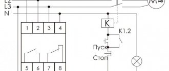
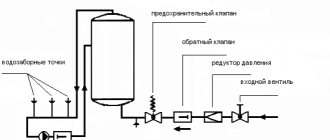
Algorithm of operation of the ATS circuit
The input circuit breaker QF1 powers section 1, QF2 powers section 2. In normal operation, each of the consumers connected to the ATS receives power from its section, while the section switch is in the off state.
If there is a loss of power at the first input, the second input supplies power, through a sectional switch, to section 1 and section 2, and, accordingly, vice versa, if there is a loss of power at the second input, the first input, through a sectional switch, provides power to sections 1 and 2.
The ATS operates in automatic mode after power is supplied to the programmable relay according to the established algorithm, with a 5 second delay in turning on and off when voltage is lost and appears on one of the inputs and the section switch is turned on and off.
When the voltage at input 1 disappears, the KSV1 relay contacts open, from 5 sec. with a delay, a command is given to turn off the circuit breaker QF1. After a certain period of time, the section switch turns on, provided that:
- Input machine QF1 is disabled
- There is voltage at input 2 (relay contacts KSV2 are closed)
- No signal ATS blocking
- Operating mode selection switch SA1 in auto position
When triggered, a light indication is given on the switchboard door QF1 (Input1) - off. QF2 (Input2) – on. QF3 (Sectional) – on. If the voltage at input 1 appears before the delay time of 5 seconds has expired, then the command to turn on the sectional switch is not given.
When power is restored at the first input, a command is given, with a delay, to turn off the sectional switch QF3. Then a command comes to turn on the first input machine.
When the input is restored, a light indication is given on the switchboard door QF1 (Input1) - on. QF2 (Input2) – on. QF3 (Sectional) – off.
When the voltage at input 2 disappears, the KSV2 relay contacts open, and a command is given to turn off the QF2 circuit breaker. The entire process is repeated in the same way as the first input.
If the voltage on both inputs is lost, the controller turns off.
The ATS operation is blocked when the motor drives of the circuit breakers are switched to manual mode, when QF1, QF2, QF3 are switched off when the protection is triggered by a signal from the emergency contact, or when the ATS control unit is faulty. In this case, it is possible to switch to manual control mode.
The alarm is reset (acknowledged) by the operator by turning off and on the controller's power, or by using a button on the front panel of the cabinet.
Involved programmable relay inputs and outputs
DI inputs
I1 – NO contact of the phase control relay KSV1 I2 – NO contact of the phase control relay KSV2 I3 – Switch SA1 (Manual-Auto) I4 – Button SB1 Reset error (blocking) ATS I5 – On-off status contact (Designation on the diagram OF) QF1 I6 – Emergency contact (Designation on the diagram SY) QF1 I7 – On-off contact (Designation on the diagram OF) QF2 I8 – Emergency contact (Designation on the diagram SY) QF2 I9 – On-off contact (Designation on the diagram OF) QF3 IA - Emergency contact (Designation on diagram SY) QF3
DO outputs
Q1 - Indication ATS operation in automatic mode Q2 - Indication ATS operation in manual mode Q3 - Indication ATS operation error Q4 - Disable the motor drive of the circuit breaker QF1 Q5 - Turn on the motor drive of the circuit breaker QF1 Q6 - Disable the motor drive of the circuit breaker QF2 Q7 - Turn on the motor circuit breaker drive QF2 Q8 – Disconnect the motor drive of the QF3 circuit breaker Q9 – Turn on the motor drive of the QF3 circuit breaker
AVR diagram - Download
Program - Download
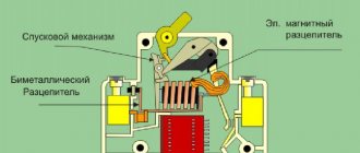
What is the machine used for?
A machine is installed in the power supply circuit to prevent overheating of the wiring. Any wiring is designed to carry a certain current. If the current passed exceeds this value, the conductor begins to heat up too much. If this situation persists for a sufficient period of time, the wiring begins to melt, resulting in a short circuit. A circuit breaker is installed to prevent this situation.
A packager or circuit breaker is necessary to prevent overheating of conductors and shutdown in the event of a short circuit
The second task of the circuit breaker is to turn off the power when a short circuit current (SC) occurs. When a short circuit occurs, the currents in the circuit increase many times over and can reach thousands of amperes. To prevent them from destroying the wiring and damaging the equipment included in the line, the circuit breaker must turn off the power as quickly as possible - as soon as the current exceeds a certain limit.
In order for the protective circuit breaker to properly perform its functions, it is necessary to correctly select the machine according to all parameters. There are not many of them - only three, but you need to deal with each one.
DESIGN
THO/II
A standard element of selective circuit breakers of the TNO series; TNO/II is a TN12 load switch, closed in a sealed steel tank filled with SF6 gas. The reservoir meets the leak-tight criteria of IEC 56. This means that it does not need to be refilled during normal operation of the load switch. In accordance with existing technical supervision rules for pressure equipment, the device is not subject to mandatory technical supervision of pressure equipment due to the low SF6 content in the tank. In combination with a modern and reliable remote radio monitoring system, it guarantees many years of operation without the need for technical inspections, adjustment and preservation of contacts, which is especially important on long air networks. The contacts of the load switches inside the tank are connected to bushings, allowing the installation of “self-cleaning” silicone insulators 24 (25) kV, 36 kV, with excellent hydrophobic properties, to which overhead or cable line bridges are connected, and it is also possible to attach corner adapters. For remote control, a simple and reliable electric drive with a single-spring or double-spring mechanism is used, guaranteeing instantaneous connection and disconnection of the main contacts of the load switch within 50 ms. Motor drives, which are installed in load switches and sectional switches of the TNO series, interact with all control and supervision systems through radio communication in Smart Grid systems.
Electric drives are available in two versions:
- Single-spring drive “T-1” - with a total response time of 5, 6 s,
- Double-spring drive “T-2” - interacts with fully automatic automatic reclosure, which serves to quickly disconnect damaged network fragments during a voltage-free break with a “disconnect” response time of 0.1 s.
The T-1 or T-2 motor drive is built directly into the load switch reservoir and coupled to its main operating shaft, which eliminates the possibility of tampering with the device by unauthorized persons and minimizes the possibility of erroneous alarms and non-operations. The spring mechanism, as well as the motor, have signal contacts that inform the SCADA system about the status of the device’s position, as well as an optical indicator that is visible from the ground. Each load switch is equipped with a manual actuator that allows the device to be operated manually from the ground, this actuator is designed to be mechanically locked in the armed or open position with the possibility of installing a padlock. Detailed information about load switches (sectional switches) can be found on the website www.zpue.com, as well as in the data sheet.
What is the difference between black and white envy?
Envy is a very unusual concept in human character. Psychologists think so. Lexicographers have their own opinion. If we turn to the dictionaries of Russian linguists Dahl, Ushakov, Ozhogov, they agree on one thing: “Envy is a person’s desire to have what others have.” Most likely - in terms of wealth, material wealth, external data and even talent.
And I'm not surprised. In fact, everything fits together. It is not for nothing that the writer Yu. Bondarev called human envy a “blind prostitute.” After all, there were enough envious people during all periods of the existence of life on Earth.
And it is very difficult to understand between the concepts of black and white envy. It is precisely about white envy that the poet V. Ryzhov spoke clearly and clearly:
“Isn’t there white envy,
Envy of integrity, which is next to troubles.
To those who will not forget what is promised,
To those who will not lie to enemies and women.”
CHARACTERISTIC
- There is no need for regular inspection and maintenance of the main switch contacts, which greatly reduces operating costs.
- Trouble-free operation in extreme natural conditions (frost, icing, wind, forest zone)
- Low consumption and prevention of aging of all active components is caused by the use of SF6, resulting in higher reliability and excellent mechanical as well as electrical strength.
- Each load switch of the TNO series is equipped with a pressure sensor “pressostat” SF6, which monitors the pressure in the tank and is responsible for the correct operation of the load switch, and in the event of an accident, automatically cuts off the engine power supply system and at the same time prevents the execution of the “disconnect” command.
- Load switches of the TNO series are equipped with a manual emergency drive, which can perform switching operations at full rated current load in case of discharge of batteries built into the on-site telemechanics cabinet.
Summary
The rated current of the circuit breaker is not equal to the maximum permissible for the cable! Due to the design features, the circuit breaker can pass through itself for a long time currents significantly higher than the rated ones and not turn off.
Different types of electromagnetic releases allow you to avoid false alarms, but using type C, and especially type D, you need to understand what's what.
If the short circuit current in your line is huge, then the breaking capacity of the circuit breaker must be even greater.
And to know the short circuit current, it needs to be measured with a specialized device. And only after measurement can we say whether the protection will work correctly
I would like to thank everyone who took part in reviewing the draft. I would be glad to point out factual errors in the article and valuable additions.
Source
Parameters of load switches, sectional switches of the TNO series
Compliance:
- PN-EN 62271-103:2011 - High-voltage distribution and control equipment. Part 103: Load switches with rated voltage above 1 kV up to and including 52 kV;
- PN-EN 62271-1:2009+A1:2011 - High-voltage distribution and control equipment. Part 1: General regulations;
- PN-EN 62271-102:2005; PN-EN 62271-102:2005/A1:2011 - High-voltage distribution and control equipment. Part 102: High Voltage AC Disconnectors and Earthing Switches;
- PN-EN 60529:2003 - Degree of protection provided by enclosures (IP code);
- PN-EN 62271-4:2014-03 - High-voltage distribution and control equipment. Part 4: Handling procedures for sulfur hexafluoride (SF6) and its mixtures;
- PN-EN 61140:2005/A1 - Protection against electric shock - general aspects for installations and equipment;
| Parameters of load switches, sectional switches of the TNO series | ||
| Type | THO-24 THO-24/II | THO-36 |
| Rated voltage Ur | 24 (25) kV | 36 kV |
| Rated frequency - number of phases fr | 50 Hz - 3 | |
| Test rated voltage at mains frequency - dry and in the rain - 1 min. Ud | ||
| - relative to ground and between phases | 50 kV | 70 kV |
| — Safe isolation gap | 60 kV | 80 kV |
| Lightning impulse test voltage (1.2/ 50 µs) Up | ||
| - relative to ground and between phases | 125 kV | 170 kV |
| — Safe isolation gap | 145 kV | 195 kV |
| Constant rated current Ir | 630 A | |
| Rated thermal current Ik | 16kA (1c) | |
| Peak rated current Ip | 40 kA | |
| Rated short-circuit making current Ima | 40 kA | |
| Rated breaking current in a low inductance circuit Iload | 630 A | |
| Rated breaking current in the ring network circuit Iloop | 630 A | |
| Rated charging interruption current of cables Icc | 60 A | |
| Arc resistance | 16k A | |
| Mechanical life (cycle - “on and off”) | 5000 | |
| Ambient temperature | — 40°C + 60°C | |
| Electric strength | E3 | |
What types of packages are there?
They are classified according to their degree of protection. And the purpose of this or that PV depends on this:
- Open. Designed for installation in dry, dust-free and inaccessible places. They do not tolerate high levels of humidity. As a rule, they are installed in iron boxes, shields and niches.
- Protected. They prevent not only accidental touches, but also objects from falling onto bare contacts. The housing is made of plastic and protects the bag from dust and moisture, so it can be installed outside the electrical panel.
- Sealed. Durable aluminum housing provides better protection against moisture. Such bags are installed not only in very damp rooms, but also in open areas.
Based on the type of fastening, bags are manufactured in 4 options:
- The fastener is located behind a 4 mm panel. Snaps into place with a front clip. The wire entry is at the rear.
- The fastener is located behind the 24 mm panel. It is also fixed with a front bracket, and the wires are connected from the back.
- The package switch is attached to the housing itself.
- The fastener is located in the cabinet, and is latched with a rear bracket. The wire entry is located at the front.
On a note! It is easier and more reliable to mount the connected package on the DIN rail into the distribution panel.
LEGEND
THO-24-T1 is a load switch for overhead lines with a rated voltage of 24(25) kV with a standard motor drive.- THO-24-T1b - load switch for overhead lines with a rated voltage of 24 (25) kV with a standard motor drive, as well as load switch blocking indication.
- THO-24-T2 - load switch for overhead lines with a rated voltage of 24 (25) kV with a battery motor drive.
- THO/T-24-T1 - load switch for overhead lines with a rated voltage of 24 (25) kV with a motor drive without a battery.
- THO-36-T1 is a load switch for overhead lines with a rated voltage of 36 kV with a standard motor drive.
- THO-36-T2 is a load switch for overhead lines with a rated voltage of 36 kV with a battery motor drive.
- THO/T-36-T1 - load switch with earthing switch for overhead lines with a rated voltage of 36 kV with a motor drive without a battery.
- THO-24/II-T1 is a section switch with two disconnectors for overhead lines with a rated voltage of 24(25) kV with a standard motor drive.
- THO-24/II-T1b is a section switch with two disconnectors for overhead lines with a rated voltage of 24 (25) kV with a standard motor drive, as well as a load switch blocking indicator.
- THO-24/II-T2 is a section switch with two disconnectors for overhead lines with a rated voltage of 24(25) kV with a battery motor drive.
- THO/T-24/II-T1 - sectional switch with two disconnectors for overhead lines with a rated voltage of 24 (25) kV with a motor drive without a battery.
Note: * motor drive with indication of blocking setting is only possible in motor drive T1, without grounding switch.