Characteristics of an NTC thermistor Calculation of temperature Connection diagrams Connection of a thermistor Connection to the ADC of an ATmega microcontroller Calculation of a table of values Example of use
Author: Pogrebnyak Dmitry
Samara, 2013.
Click here to read this article in English.
One option for measuring temperature is to use thermistors. Among the advantages of a thermistor is a large temperature coefficient, that is, a significant change in resistance depending on temperature (about 2-10% per Kelvin). There are two types of thermistors: with a positive temperature coefficient (PTC, Positive Temperature Coefficient), that is, their resistance increases with increasing temperature, and with a negative one (NTC, Negative Temperature Coefficient), which decreases their resistance with increasing temperature. This article will talk about the latter, and about their use for temperature measurement in combination with AVR microcontrollers
What is NTC thermistor
An NTC thermistor means components whose resistance varies under the influence of temperature conditions. The scope of application of this radioelement depends on its properties. Basically, thermistors are needed to take measurements and control temperature indicators. Also used to detect liquid or record its absence. NTC thermistors are also found in current limiting devices. The range of their use is wide, from radio amateurs to reputable large-scale production.
Among the tasks assigned to NTC thermistors, temperature control is considered important. Therefore, it is difficult for developers of both complex industrial equipment and simple household appliances to do without these elements.
The modern market offers a large selection of NTC thermistors from manufacturers representing different countries of the world. This element was first invented back in 1930. It was introduced by scientist Samuel Reuben.
PTC
Unlike the thermistors discussed above, PTC thermistors have a positive resistance coefficient. This means that if the part heats up, its resistance also increases. Such products were actively used in old televisions equipped with color telescopes.
Today, there are two types of PTC thermistors (depending on the number of pins) - with two and three taps. The difference between three-terminal products is that they contain two positrons, shaped like “tablets”, installed in one housing.
Outwardly it may seem that these elements are identical, but in practice this is not the case. One of the “tablets” is smaller. The resistance also differs - from 1.3 to 3.6 kOhm in the first case, and from 18 to 24 Ohm for the second such tablet.
Two-terminal thermistors are manufactured using semiconductor material (most often Si - silicon). Externally, the product looks like a small plate with two terminals at different ends.
PTC thermistors are used in various fields. Most often they are used to protect power equipment from overload or overheating, as well as to maintain a safe temperature.
Main areas of application:
- Protection of electric motors. The purpose of the product is to protect the winding from burnout in the event of a rotor wedge or in the event of a breakdown of the cooling system. The posistor plays the role of a sensor connected to a control device with executing relays, contactors and starters. When a force majeure situation occurs, the resistance increases, and the signal is sent to the control element, which gives the command to turn off the motor.
- Protection of transformer windings from overheating or overload. In such a circuit, a posistor is installed in the primary winding circuit.
- Heating unit in glue guns.
- In cars for heating the intake tract.
- Demagnetization of CRT picture tubes, etc.
NTC Thermistor Range
The main classification by type is related to the production process that was used in the manufacture of the radio element:
- beaded;
- disk and chip;
- in a glass shell.
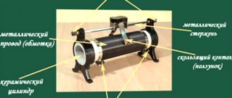
The bead thermistor is specially baked into a housing part made of ceramic material. The component itself is an alloy of platinum in lead wire. This type is distinguished by its fast response. The thermistor is able to function smoothly at high temperatures.
Chip and disk thermistors are usually made of metallized contacts. They have the ability to withstand high currents.
Thermistors equipped with a glass shell can operate at temperatures of +150 degrees and above. These are sealed radioelements, which are sealed in a glass vial that does not allow air flow. They are not exposed to climatic conditions, so they can be installed on open surfaces of boards.
All of the above types have good mechanical strength of the housing, high sensitivity and are reliable in practice, which makes it possible to use them in motors, fluorescent lamps, transformers, electric motors with a direct current not exceeding 20 A, household, industrial and auto electronics, mobile devices, modern monitors with LCD and HDD characteristics.
Disk and chip thermistors
Thermistors.
Thermistor in the form of a disk. NTC thermistors have metallized surface contacts. They are larger and, as a result, have slower response times than ball-type NTC resistors. However, due to their size, they have a higher dissipation constant (the power required to raise their temperature by 1 °C), and since the power dissipated by a thermistor is proportional to the square of the current, they can handle higher currents much better than ball-type thermistors . Disc-type thermistors are produced by pressing a mixture of oxide powders into a circular matrix, which is then sintered at high temperatures. Chips are typically made by injection molding, where a suspension of material is spread into a thick film, dried, and cut into a shape. Typical sizes range from 0.25 to 25 mm in diameter.
Groups of thermistors, their characteristics
All NTC thermistors are divided into groups depending on the temperature they can withstand. This parameter explains in which mode the device is capable of operating, and where it simply cannot cope with its functional responsibilities.
Thermistors are:
- low temperature (up to 170K);
- medium temperature (170–510K);
- high temperature (900–1300K).
Thermistors are also divided into thermistors and posistors. The former have a negative temperature coefficient (TCC), while the latter have a positive temperature coefficient. Another variety is known - a combined component. For example, an NTC thermistor, which has indirect heating. The device body contains a sensor equipped with a heating element. It sets the temperature of the thermistor and the initial current resistance. These radioelements are found in practice in the form of variable resistors that control the voltage applied to the heating sensor.
Classification depending on the operating principle
Based on the principle of operation, thermistors are divided into:
- contact;
- contactless.
The first category usually includes bimetallic elements, various temperature sensors, and thermocouples. If we are talking about a non-contact operating principle, then these are sensors with an infrared option. They are capable of detecting infrared radiation and optical rays emitted by liquids and gases.
NTC characteristic curve
As can be seen from the figure, NTC thermistors have a much steeper resistance-temperature slope compared to platinum alloy RTDs, resulting in better temperature sensitivity. However, RTDs remain the most accurate sensors, accurate to within ±0.5% of the measured temperature, and are useful over a temperature range of -200°C to 800°C, much wider than NTC temperature sensors.
Comparison with other temperature sensors
Compared to RTDs, NTCs are smaller in size, faster in response, more resistant to shock and vibration, and have a lower cost. They are slightly less accurate than RTDs. Compared to thermocouples, the accuracy obtained from both is similar; however, thermocouples can withstand very high temperatures (on the order of 600 °C) and are used in place of NTC thermistors, where they are sometimes called pyrometers. However, NTC thermistors provide greater sensitivity, stability, and accuracy than thermocouples at lower temperatures, and are used with less power and therefore have lower overall costs. The cost is further reduced by eliminating the need for signal conditioning circuits (amplifiers, level translators, etc.) that are often needed when working with RTDs and are always needed for thermocouples.
Self-heating effect
The self-heating effect is a phenomenon that occurs when current flows through an NTC thermistor. Since a thermistor is basically a resistor, it dissipates energy as heat when current flows through it. This heat is generated in the thermistor core and affects the accuracy of the measurements. The extent to which this occurs depends on the amount of current flowing, the environment (whether it is liquid or gas, whether there is any flow above the NTC sensor, etc.), temperature coefficient of the thermistor, total amount of thermistor area, etc. The fact that the resistance of an NTC sensor, and therefore the current flowing through it, depends on the environment and is often used in liquid storage tanks.
Heat capacity
Heat capacity is the amount of heat required to raise the temperature of the thermistor by 1°C and is usually expressed in mJ/°C. Knowing the exact heat capacity is important when using an NTC thermistor sensor as an inrush current limiter because it determines the speed of response of the NTC temperature sensor.
Curve selection and calculation
A careful selection process should consider the thermistor dissipation constant, heat treatment time constant, resistance value, resistance-resistance curve and tolerances to account for the most important factors. Because the relationship between resistance and temperature (RT curve) is highly nonlinear, certain approximations must be used in practical system designs.
First order approximation
One approximation and the simplest to use is the first order approximation, which states that: The first order approximation formula is: dR = k * dT Where k is the negative temperature coefficient, ΔT is the temperature difference, ΔR is the change in resistance resulting from the change in temperature. This first-order approximation is valid only for a very narrow temperature range and can only be used for temperatures where k is almost constant over the entire temperature range. Beta Formula Another equation gives satisfactory results with an accuracy of ±1°C over the range 0°C to +100°C. It depends on a single material constant β, which can be obtained by measurement. The equation can be written as: Beta equation: R (T) = R (T0) * exp (beta * (1 / T-1 / T0)) Where R (T) is the resistance at temperature T in Kelvin, R (T0 ) is the reference point at temperature T0. The beta formula requires two-point calibration and is typically no more than ±5°C over the entire useful range of the NTC thermistor. Steinhart-Hart Equation The best approximation known to date is the Steinhart-Hart formula, published in 1968: Steinhart equation for exact approximation: 1/T = A + B * (ln(R)) + C * (ln(R) )) ^ 3 Where ln R is the natural logarithm of the resistance at temperature T in Kelvin, and A, B and C are coefficients obtained from experimental measurements. These factors are usually published by thermistor suppliers as part of a data sheet. The Steinhart-Hart formula is typically about ±0.15°C over the -50°C to +150°C range, which is large for most applications. If high accuracy is required, the temperature range should be reduced and the accuracy is better than ±0.01°C in the range from 0°C to +100°C.
Choosing the Right Approximation
The choice of formula used to derive temperature from resistance measurements should be based on available computing power as well as actual tolerance requirements. In some applications the first order approximation is more than sufficient, while in other cases even the Steinhart-Hart equation suffices and the thermistor must be calibrated point by point, making a large number of measurements and creating a lookup table.
Design and properties of NTC thermistors
Materials commonly used in the manufacture of NTC resistors are platinum, nickel, cobalt, iron and silicon oxides, used as pure elements or ceramics and polymers. NTC thermistors can be divided into three groups, depending on the manufacturing process used.
Designations and explanation of markings
There are several types of markings. For example, from letters or different colors, stripes or other images applied to the surface of the thermistor. It all depends on the manufacturer and the specific type of elements. An approximate notation system is shown in the picture below. There are so many options that even an experienced master cannot always decipher them correctly. In this case, it is better to rely on the technical data that is on the thermistor manufacturer’s website in the description of a specific element.
Let's look at an example - an NTC thermistor marked 10 D-9. The first digit “10” indicates that 10 ohms at 25 degrees Celsius constitutes the resistance of the sensor. Its diameter is 9 mm. The higher this value is, the higher the power it dissipates. To better understand color markings, you should use a table or look at the description of characteristics in the reference book. All manufacturers clarify this information for their product lines.
The shape of a semiconductor can be different: thin pipes, large washers, plates of different thicknesses and small elements of different types. There are even parts whose dimensions are measured in several microns. The picture below shows an assortment of semiconductors that are more common than others on the modern market.
Usage example
The example below uses output to a seven-sigment indicator.
For a description of working with the indicator, see my other article.
| Displaying the temperature value on the CC56-12GWA indicator |
ADMUX = 0b01000111; // reference voltage - Vcc, input ADC7, result on the right edge ADCSRA = 0b10000111; // 1/128 frequency divider, enable ADC while(1) { temperature_table_entry_type summ = 0; for (uint8_t i = 0; i < 64; i++) { ADCSRA |= _BV(ADSC); loop_until_bit_is_clear(ADCSRA, ADSC); sum += ADC; } int16_t t = calc_temperature(summ); ledind_num(t, 1, 0b01010011); // Output the value to the indicator with a prefix in the form of the letter t _delay_ms(250); }
Main characteristics of thermistors
It is important to pay attention to the characteristics of NTC thermistors. They may change for a number of reasons: manufacturer, type and material used. First of all, the buyer should study the size. It is necessary that the element fits in size, that is, fits on the board during installation.
The following important points:
- resistance RT;
- time constant;
- dissipation coefficient.
These are the main points to consider when purchasing a part.
Heating characteristics
There are 2 types of thermistors, depending on the heating method underlying their operating principle:
- indirect;
- straight.
With indirect heating, the temperature of the thermistor will change under the influence of elements placed next to it.
When direct, it also changes, but only under the influence of the surrounding air or the current that passes through the element. This is the main difference.
Thermistors
Bead or ball shape. These NTC thermistors are made of platinum alloy lead wires directly sintered into a ceramic body. They typically provide faster response times, better stability, and can operate at higher temperatures than NTC disk and chip sensors, but are more fragile. They usually seal them in glass to protect them from mechanical damage during assembly and improve their measurement stability. Typical sizes range from 0.075 to 5 mm in diameter.
Checking the serviceability of the part
First you need to set the multimeter to a mode that will allow you to measure resistance. After this, connect the probes to the legs of the radio element. Fix the resistance and bring the soldering iron to the element. It is better to record resistance indicators on paper. The soldering iron must be preheated. Carry out control measurements. If the resistance drops, then the thermistor is working correctly. If it is a posistor, then the resistance should increase.
For example, when testing the NTC MF 72 thermistor, the resistance is 6.9 Ohms, but when changing the temperature using a soldering iron, it drops to 2 Ohms. The test result is correct.
When the resistance remains the same or changes suddenly, you can assume that the NTC thermistor has failed. I would like to additionally note that such checks are highly discouraged because they are crude. If the goal is to accurately control the thermistor, you need to check its temperature, then the resistance. The data must be compared with the parameters indicated by the manufacturer in the specifications.
Connection diagrams
Thermistor connection
| Scheme A |
| Scheme B |
| Scheme C |
| Scheme D |
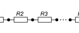
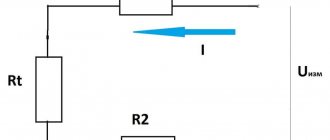
The simplest connection option is circuit A. By choosing the value of the resistor RA approximately equal to the thermistor resistance in the region of the measured temperatures, the U values will change closer to linear, which will provide greater accuracy when interpolating table values.
When choosing RA and thermistor ratings, it should be taken into account that the current flowing through the thermistor causes it to heat up and, as a result, distort the readings. It is desirable that the power at the thermistor does not exceed 1 mW. This means that at a voltage U0 = 5V, RA must be at least 10 kiloOhms. The thermistor resistance in the measured range should be approximately the same order.
Circuit B is designed to limit the power dissipated in the thermistor.
Circuits C and D are the inverse of A and B. It makes sense to use them if you need to measure low temperatures when the ADC reference value (Uref) is below U0.
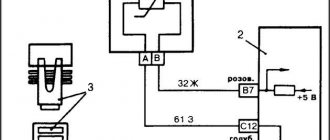
Connecting to the ATmega microcontroller ADC
| Connecting the ADC of ATmega microcontrollers |
ATmega controllers use a separate power line for the ADC module to reduce noise. The instructions recommend connecting these inputs through a filter: inductance L = 10 μH, and capacitor C2 = 0.1 μF.
The microcontroller can use either an external reference voltage for the ADC, or an internal one (2.56V or 1.1V), or, as such, use the ADC supply voltage: AVCC. When using external voltage, it must be applied to the AREF input. When using AVCC, or 2.56V internal voltage, a capacitor must be placed between this input and ground (in diagram C1). The instructions do not give clear instructions for choosing the capacitor capacity; I recommend using a ceramic capacitor of 0.1 µF or more.
To reduce the measured noise, I recommend that the thermistor also be connected to the filtered voltage in parallel with AVCC, and configured to use this voltage as a reference voltage.
Additionally, to suppress noise occurring on the lines, you can install capacitor C3 in the range of 1-100nF.
Please note that in addition to the ADC module, the AVCC input also powers some of the I/O ports (usually on the same pins used for the ADC). Using these ports as output and connecting loads to them can create additional noise in the ADC.
To level out the noise that occurs on the ADC, I recommend taking measurements several times in a row and summing up the obtained values. ATmega microcontrollers have a 10-bit ADC. Having summed the results of 64 consecutive measurements, the result remains within a 16-bit unsigned integer, which does not require additional memory to save the table of values. For larger numbers of measurements, it is also possible to stay within 16 bits by shifting or dividing the result accordingly.
NTC benefits
Thermistors are in much greater demand than posistors. They have a number of advantages. These are elements that can be used reliably for a long time without worrying about their failure, even despite extreme environmental conditions. Another plus is its compact dimensions.
The packaging is so convenient that the use of radioelements is possible in a small area or in a limited space; they do not require much space on the board. Another advantage is fast response time. They react to changes in temperature if there is a need for feedback. Cost-effectiveness indicators are no less important.
The master can count on an inexpensive price, as well as simple installation. But even such an advantageous element is not without its drawbacks. It lies in the fact that in the conditions of modern production there is no possibility of producing it in mass quantities, maintaining the same characteristics. The parameters are very different. This applies to cases where elements are produced in one batch. For this reason, it is necessary to re-configure the equipment.
Advantages and disadvantages of NTC and PTC
NTC thermistors are rugged, reliable and stable, and they are equipped to withstand extreme environmental conditions and resist interference to a greater degree than other types of temperature sensors.
- Compact Size: Packaging options allow them to work in small or confined spaces; thereby taking up less space on printed circuit boards.
- Fast response time: The small size allows for quick response to temperature changes, which is important when immediate feedback is required.
- Cost-effective: Thermistors are not only cheaper than other types of temperature sensors; If the thermistor purchased has the correct RT curve, no other calibration is required during installation or during its service life.
- Matching points: the ability to obtain a certain resistance at a certain temperature.
- Curve matching: Replaceable thermistors with an accuracy of +.
Thermistor on the diagram
Thermistors are easy to use, inexpensive, durable, and respond predictably to changes in temperature. Although they do not perform well at extremely high or low temperatures, they are the sensor of choice for applications that measure temperature at a desired reference point. They are ideal when very precise temperatures are required. Some of the most common uses of thermistors are in digital thermometers, in cars for measuring oil and coolant temperatures, and in household appliances such as ovens and refrigerators, but they are also found in almost any application where safety heating circuits are required for safety or cooling.
For more complex applications such as laser stabilized detectors, optical assemblies and charge-coupled devices, a thermistor is integrated. For example, a 10K ohm thermistor is a standard that is built into laser packages.
Disk and chip thermistors
Thermistor in the form of a disk. NTC thermistors have metallized surface contacts. They are larger and, as a result, have slower response times than ball-type NTC resistors. However, due to their size, they have a higher dissipation constant (the power required to raise their temperature by 1 °C), and since the power dissipated by a thermistor is proportional to the square of the current, they can handle higher currents much better than ball-type thermistors . Disc-type thermistors are produced by pressing a mixture of oxide powders into a circular matrix, which is then sintered at high temperatures. Chips are typically made by injection molding, where a suspension of material is spread into a thick film, dried, and cut into a shape. Typical sizes range from 0.25 to 25 mm in diameter.
It will be interesting➡ What are thyristors?
Interesting material to familiarize yourself with: what you need to know about the design of a power transformer.
Encapsulated NTC Thermistors
These are NTC temperature sensors sealed in an airtight glass bubble. They are designed for use at temperatures above 150°C or for PCB mounting where durability is required. Encapsulating the thermistor in glass increases the stability of the sensor as well as protecting the sensor from the environment. They are manufactured by hermetically sealing NTC type resistors into a glass container. Typical sizes range from 0.4 to 10 mm in diameter.
Typical Applications
NTC thermistors are used in a wide range of applications. They are used for temperature measurement, control temperature and temperature compensation. They can also be used to detect the absence or presence of liquid, as current limiting devices in power circuits, temperature monitoring in automotive components, and many others. NTC sensors can be divided into three groups, depending on the electrical characteristics used in units and devices.
Resistance-temperature characteristic
Applications based on the resistance-time characteristic include temperature measurement, control and compensation. This also includes situations in which an NTC thermistor is used, so that the temperature of the NTC temperature sensor is related to some other physical phenomena. This group of units requires the thermistor to operate under zero power conditions, which means that the current passing through it is kept as low as possible to avoid heating the probe.
Devices based on the current time characteristic are: time delay, inrush current limiting, surge suppression and much more. These characteristics are related to the heat capacity and dissipation constant of the NTC thermistor used. The circuit typically relies on an NTC thermistor, heating up due to the current passing through it. At some point this will cause some kind of change in the circuit, depending on the device in which it is used.
Popular thermistors
As mentioned above, many forms and types of thermistors are known today. Often there are parts in phenol with a special coloring. It is impossible to say unequivocally and accurately which type or form is the most popular. The shape depends on what task is assigned to the thermistor; its characteristics also matter.
Bead thermistors are considered the optimal solution for installation in a device. The disk version is more appropriate for surfaces with optical properties. If we talk about the chip form, installation is recommended on a printed circuit board. When determining this characteristic, the master should take into account how tight the contact between the surface and the device should be. Whatever the type of thermistor, it is important that a thermally conductive paste or epoxy adhesive that does not have electrical conductivity properties is used to connect it to the surface.
If the task is to replace the thermistor, you should use a similar element, having studied its characteristics in the reference book or technical documentation. The technician can replace the thermistor with a regular wirewound resistor, but only if he has had similar experience in the past, and if there were no problems with the operation of the device the previous time. Be sure to check the optionality conditions of the element both in time and voltage. It is also important to understand whether the new resistor fully performs the functions of a thermistor.
Device and types
A thermistor is a semiconductor element that, depending on its type, changes resistance as the temperature rises/falls. Today there are two types of products:
- Thermistors are negative temperature coefficient (NTC) parts. Their peculiarity is that the resistance drops with increasing temperature.
- PTC resistors are elements that have a “positive” temperature coefficient (PTC). Unlike the previous form, as T increases, the resistance, on the contrary, increases.
Depending on the type of semiconductor, different elements are used in its production. As noted, when creating resistive elements, oxides, chalcogenides and halides of various metals are used, and the design may vary depending on the application.
More about the scope
All thermistors can be used in a fairly wide range of applications. If we are talking about a more expensive device, this allows it to be made part of complex production equipment or used as a fuse. Specialists connect thermistors to relays. This allows the system to turn off automatically as soon as it detects overheating. In terms of price, thermistors are much less expensive than other components. This explains the high demand for them in the market. They are used both in everyday life and in production.
With proper configuration and installation of the thermistor, it can become an element for checking the temperature conditions outdoors or indoors. You can use it to track any changes. Of course, we are not talking about such accurate measurements as is required in production areas. A step of one degree will be enough. The part is also often used in the engine protection system against overheating. In this case, the specialist connects it to the relay. If a heating hazard occurs that violates all acceptable safety precautions, the engine is switched off. If you have experience, you can include a thermistor in the on-board PC system. This allows you to track indicators on the monitor, which is a very convenient solution in practice.
All thermistors are produced in housings with protective properties, which eliminates the influence of moisture on them. This has a positive effect on the service life of the element. If a specialist selects the thermistor correctly, he can count on long-term use of the element and the equipment in which it will be installed.
General operating principle
Thermistors are made as sensitive as possible to changes in temperature, because they work on this principle. In the absence of heating, the atoms that make up the part are in the correct order and form long rows.
In case of heating, the number of active “charge carriers” increases. The more such units, the higher the conductivity of the material.
When studying the curve of resistance versus temperature, you can see a nonlinear type characteristic. At the same time, the thermistor shows the best characteristics in the range from -90 to +130 degrees.
It is important to take into account that the operating principle of such parts is based on the correlation between the temperature regime and the metals in the part.
The thermistor itself is made using semiconductor compounds (oxides, manganese, copper, nickel, silicates, iron and others). Such components are able to respond to the slightest change in temperature.
The created electric field pushes the electron, which moves until it hits the atom. For this reason, the movement of the electron is slowed down.
As temperature increases, atoms move more actively. Under such circumstances, the original act will collide with another element more quickly. As a result, additional resistance arises.
After the operating temperature decreases, electrons “fall” into lower valence levels and enter an unexcited state. In other words, they move less and do not create as much resistance.
If the temperature rises, the R indicator also increases. But here you need to take into account the type of thermistor, on which the principle of increasing and increasing resistance when the temperature changes depends.
NTC thermistor characteristics
Do you know what an NTC thermistor is and what are its characteristics?
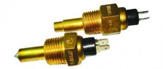
NTC thermistor
What are NTC thermistors?
The thermistor built into the stainless steel probe is a "negative temperature coefficient". NTC thermistors are negative temperature coefficient resistors, which means the resistance decreases as temperature increases. They are mainly used as resistive temperature sensors and current limiting devices. The temperature sensitivity coefficient is approximately five times greater than silicon temperature sensors (silistors) and approximately ten times greater than resistance temperature sensors (RTDs). NTC sensors are typically used between -55°C and 200°C.
NTC thermistor
The nonlinearity of the relationship between resistance and temperature exhibited by NTC resistors has been a major problem when using analog circuits to accurately measure temperature, but the rapid development of digital circuits has solved this problem, allowing precise values to be calculated by interpolating lookup tables or by solving equations that approximate the typical NTC curve.
NTC Thermistor Definition
An NTC thermistor is a temperature-sensitive resistor whose resistance exhibits a large, precise, and predictable decrease as the temperature of the resistor core increases over a range of operating temperatures.
Characteristics of NTC thermistors
Unlike RTDs (resistance temperature detectors) that are made of metals, NTC thermistors are usually made of ceramics or polymers. Different materials used result in different temperature responses as well as other characteristics.
Although most NTC thermistors are generally suitable for use in the temperature range of -55°C to 200°C, where they give the most accurate readings, there are special families of NTC thermistors that can be used at temperatures approaching absolute zero (-273.15° C), as well as those specifically designed for use above 150 °C.
The temperature sensitivity of an NTC sensor is expressed as "percentage change per degree C". Depending on the materials used and the manufacturing process, typical temperature sensitivity values range from -3% to -6% per °C.
Characteristic curve of NTC thermistor
NTC characteristic curve
As can be seen from the figure, NTC thermistors have a much steeper resistance-temperature slope compared to platinum alloy RTDs, resulting in better temperature sensitivity. However, RTDs remain the most accurate sensors, accurate to within ±0.5% of the measured temperature, and are useful over a temperature range of -200°C to 800°C, much wider than NTC temperature sensors.
Comparison with other temperature sensors
Compared to RTDs, NTCs are smaller in size, faster in response, more resistant to shock and vibration, and have a lower cost. They are slightly less accurate than RTDs. Compared to thermocouples, the accuracy obtained from both is similar; however, thermocouples can withstand very high temperatures (on the order of 600 °C) and are used in place of NTC thermistors, where they are sometimes called pyrometers. However, NTC thermistors provide greater sensitivity, stability, and accuracy than thermocouples at lower temperatures, and are used with less power and therefore have lower overall costs. The cost is further reduced by eliminating the need for signal conditioning circuits (amplifiers, level translators, etc.) that are often needed when working with RTDs and are always needed for thermocouples.
Self-heating effect
The self-heating effect is a phenomenon that occurs when current flows through an NTC thermistor. Since a thermistor is basically a resistor, it dissipates energy as heat when current flows through it. This heat is generated in the thermistor core and affects the accuracy of the measurements. The extent to which this occurs depends on the amount of current flowing, the environment (whether it is liquid or gas, whether there is any flow above the NTC sensor, etc.), temperature coefficient of the thermistor, total amount of thermistor area, etc. The fact that the resistance of an NTC sensor, and therefore the current flowing through it, depends on the environment and is often used in liquid storage tanks.
Heat capacity
Heat capacity is the amount of heat required to raise the temperature of the thermistor by 1°C and is usually expressed in mJ/°C. Knowing the exact heat capacity is important when using an NTC thermistor sensor as an inrush current limiter because it determines the speed of response of the NTC temperature sensor.
Curve selection and calculation
A careful selection process should consider the thermistor dissipation constant, heat treatment time constant, resistance value, resistance-resistance curve and tolerances to account for the most important factors. Because the relationship between resistance and temperature (RT curve) is highly nonlinear, certain approximations must be used in practical system designs.
First order approximation
One approximation, and the simplest to use, is the first-order approximation, which states that:
first order approximation formula: dR = k * dT
Where k is the negative temperature coefficient, ΔT is the temperature difference, ΔR is the change in resistance resulting from the change in temperature. This first-order approximation is valid only for a very narrow temperature range and can only be used for temperatures where k is almost constant over the entire temperature range.
Another equation gives satisfactory results with an accuracy of ±1°C over the range from 0°C to +100°C. It depends on a single material constant β, which can be obtained by measurement. The equation can be written as:
Beta equation: R(T) = R(T0) * exp(beta * (1/T-1/T0))
Where R(T) is the resistance at temperature T in Kelvin, R(T0) is the reference point at temperature T0. The beta formula requires two-point calibration and is typically no more than ±5°C over the entire useful range of the NTC thermistor.
The best approximation known to date is the Steinhart-Hart formula, published in 1968:
Steinhart equation for exact approximation: 1/T = A + B * (ln(R)) + C * (ln(R))^3
Where ln R is the natural logarithm of the resistance at temperature T in Kelvin, and A, B and C are coefficients obtained from experimental measurements. These factors are usually published by thermistor suppliers as part of a data sheet. The Steinhart-Hart formula is typically about ±0.15°C over the -50°C to +150°C range, which is large for most applications. If high accuracy is required, the temperature range should be reduced and the accuracy is better than ±0.01°C in the range from 0°C to +100°C.
Choosing the Right Approximation
The choice of formula used to derive temperature from resistance measurements should be based on available computing power as well as actual tolerance requirements. In some applications the first order approximation is more than sufficient, while in other cases even the Steinhart-Hart equation suffices and the thermistor must be calibrated point by point, making a large number of measurements and creating a lookup table.
Design and properties of NTC thermistors
Materials commonly used in the manufacture of NTC resistors are platinum, nickel, cobalt, iron and silicon oxides, used as pure elements or ceramics and polymers. NTC thermistors can be divided into three groups, depending on the manufacturing process used.
Thermistors
Bead or ball shape. These NTC thermistors are made of platinum alloy lead wires directly sintered into a ceramic body. They typically provide faster response times, better stability, and can operate at higher temperatures than NTC disk and chip sensors, but are more fragile. They usually seal them in glass to protect them from mechanical damage during assembly and improve their measurement stability. Typical sizes range from 0.075 to 5 mm in diameter.
Thermistors
Disk and chip thermistors
Thermistor in the form of a disk. NTC thermistors have metallized surface contacts. They are larger and, as a result, have slower response times than ball-type NTC resistors. However, due to their size, they have a higher dissipation constant (the power required to raise their temperature by 1 °C), and since the power dissipated by a thermistor is proportional to the square of the current, they can handle higher currents much better than ball-type thermistors . Disc-type thermistors are produced by pressing a mixture of oxide powders into a circular matrix, which is then sintered at high temperatures. Chips are typically made by injection molding, where a suspension of material is spread into a thick film, dried, and cut into a shape. Typical sizes range from 0.25 to 25 mm in diameter.
Encapsulated NTC Thermistors
Fiberglass with NTC thermistor
These are NTC temperature sensors sealed in an airtight glass bubble. They are designed for use at temperatures above 150°C or for PCB mounting where durability is required. Encapsulating the thermistor in glass increases the stability of the sensor as well as protecting the sensor from the environment. They are manufactured by hermetically sealing NTC type resistors into a glass container. Typical sizes range from 0.4 to 10 mm in diameter.
Encapsulated NTC Thermistors
Typical Applications
NTC thermistors are used in a wide range of applications. They are used for temperature measurement, control temperature and temperature compensation. They can also be used to detect the absence or presence of liquid, as current limiting devices in power circuits, temperature monitoring in automotive components, and many others. NTC sensors can be divided into three groups, depending on the electrical characteristics used in units and devices.
Typical Applications
Resistance-temperature characteristic
Applications based on the resistance-time characteristic include temperature measurement, control and compensation. This also includes situations in which an NTC thermistor is used, so that the temperature of the NTC temperature sensor is related to some other physical phenomena. This group of units requires the thermistor to operate under zero power conditions, which means that the current passing through it is kept as low as possible to avoid heating the probe.
Current time characteristic
Devices based on the current time characteristic are: time delay, inrush current limiting, surge suppression and much more. These characteristics are related to the heat capacity and dissipation constant of the NTC thermistor used. The circuit typically relies on an NTC thermistor, heating up due to the current passing through it. At some point this will cause some kind of change in the circuit, depending on the device in which it is used.
Voltage characteristic
Devices based on the voltage and current characteristics of the thermistor typically involve changes in environmental conditions or circuit changes that result in changes in the operating point on a given curve in the circuit. Depending on the application, this can be used for current limiting, temperature compensation or temperature measurement.
NTS thermistor symbol
The following symbol is used for NTC thermistor according to IEC standard.
NTS thermistor symbol