A traction substation is a device designed to convert and supply electricity to the electric transport network. This is specialized equipment used by railways, trams, and trolleybus systems. It is also installed at all metro substations. The traction substation can reduce the voltage to an acceptable level or convert alternating current to direct current.
Application area
The traction substation has a number of features. Its design is influenced by the area of operation and purpose. Traction substations for trams and trolleybuses, metro and Russian Railways trains can differ significantly.
Electrified railways are characterized by the installation of TP every 25-50 km. Network design is carried out in accordance with a number of requirements. Technological layout maps depend on the profile of the railway, its size and transport features.
According to the purpose factors, the equipment of traction substations is classified into one of three groups. The first category includes metro traction substations. The second group includes equipment for the railway. The third category includes installations for ground urban transport.
Varieties
There are DC and AC traction substations. Each group has its own special technical characteristics. DC substations are designed for loads of 6-220 kV. Electrical communications are supplied to them by air or cable.
If the transport operates at a voltage of less than 110 kV, the design provides for step-down equipment. Entering the device, the current first decreases, and then rectifies and enters the communication networks. The design of AC traction substations is carried out without the participation of a converting unit. In this case, the design will be simpler.
To be able to rectify the voltage in the network in parallel substations when connecting the same phase, special circuits are used. They allow you to balance the connection of transformers. The most famous of them is the double screw scheme. Its use allows the phases to be loaded more evenly, avoiding consumer voltage losses.
There are mobile and stationary substations. The second option is more often used. Mobile devices play the role of batteries. Their design has certain difficulties. Therefore, they are used quite rarely.
What is a contact network
Contact network is a set of linear current-carrying, insulating, supporting and supporting elements designed to supply electricity to the substation current collectors. The contact wire is made of chalk and its alloys (copper-cadmium and copper-magnesium) with a cross-section of 65–100 mm2. On auxiliary lines and lines in depots, copper wires with a steel core may be used. The wire must have good electrical conductivity, wear resistance and high strength to allow reliable tension.
The cross-section of contact wires is selected taking into account their cost according to the so-called economic current density from the condition of the optimal ratio between the consumption of non-ferrous metals and losses of electrical energy in the traction network. The hanging height of contact wires on lines under construction or reconstruction must be 6.0 m. A reduction in the hanging height is allowed inside production premises, under bridges and overpasses - up to 4.2 m, in tunnels - up to 3.9 m.
At high current loads of the contact network or when the voltage drop at the end of the section is greater than permissible, reinforcing wires made of copper, aluminum or twisted wire made of steel and aluminum wire are laid parallel to the contact wires to increase strength. At certain intervals these wires are connected to the contact wires.
Catenary suspension is a system for suspending contact wires to supporting structures. Depending on the method of hanging, fastening and maintaining tension, catenary pendants can be simple, chain and polygon. The distance between the points of attachment of the contact wire to the supporting structures is called the catenary span length. For fastening contact wires and supporting structures, various fittings with or without insulation are used.
Traction substation - top view.
Polygon suspension is used when electric transport lines pass under artificial structures, on curved sections, city squares, etc. In this case, the entire suspension and contact wire are located in a horizontal plane. The contact wires of tram lines on straight sections of the track are arranged in a zigzag pattern with a distance from the center line of up to 400 mm for uniform wear of the current collector.
At the intersections of contact wires, air crossings and crosses are installed. They ensure the passage of PS current collectors without contact with the crossed contact wire along special guides. For this purpose, non-contact sections are organized at intersections, which the PS coasts through. Brackets, simple and chain flexible crossbars, beams and ceilings of overpasses, tunnels and other engineering structures are used as supporting devices in the contact networks of trams and trolleybuses. Flexible devices typically use galvanized steel seven-wire rope.
Supporting structures are intended for fastening supporting devices: special supports (reinforced concrete or steel), walls of brick and reinforced concrete buildings, structures of tunnels, bridges and overpasses.
The trolleybus contact network must ensure the movement of the trolleybus in the first and second lanes, and on the approaches to left turns - in the far left lane, provide for the possibility of timely changing lanes of the trolleybus, taking into account the specific road situation. The negative (zero) wire of the trolleybus contact network is located on the right side in the direction of travel.
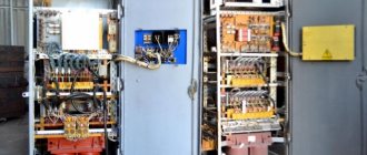
Traction substation control panel.
To change the direction of trolleybus movement, switches are installed on the contact network. Traditionally, switches of the trolleybus contact network are controlled similarly to trams, i.e. depending on the presence of traction when approaching the turnout. Modern turnouts are controlled using a radio signal from the driver's cabin. A transmitter (radio transmitting device) and a number of control buttons are installed in the cabin. On the contact network support next to the automatic switch there is a device that receives radio signals and supplies a control impulse to the switch drive, as well as a special traffic light that shows the direction of movement of the trolleybus at the current position of the switch feathers.
If the driver is satisfied with this direction, then he, without performing any actions, passes the arrow and follows the given route. If the driver needs to move the arrow in another direction, he presses a certain button on the control panel and thereby sends a radio signal that activates the arrow drive. Within 1.5-2.0 seconds, the direction of movement is switched, and the trolleybus follows a different path. After the car passes, the switch remains in its new position. Such arrows do not have de-energized elements, so the driver does not need to specifically reduce speed to pass them.
If several automatic switches are installed at one place on the route, then different buttons are used to control them. The radio transmitting device has four channels; to control each arrow at complex intersections, its own channel is determined. Similar arrows operate automatically without driver intervention.
Classification depending on purpose
In accordance with the operating conditions, the traction substation can be classified into one of the following groups. For railway transport, support, dead-end, and intermediate varieties are used. In the first case, the installation can be used to power other objects. Dead-end devices are provided with electric current from neighboring substations, and intermediate ones - from two neighboring installations.
Special types are used for trolleybuses and trams. The first group of devices requires the participation of maintenance personnel. The second category is fully automated. The third category includes remote-controlled equipment. The management of such stations does not require the participation of personnel.
For the subway, step-down, traction and traction-step-down devices are used. In the first option, the system is powered by city power supply equipment. The second type reduces the voltage to 400-220 V. Its energy is used to power lighting and power devices.
Metropolitan
It is characterized by short distances (distance between stations) and no problems connecting to power lines. Therefore, only direct current is supplied to the contact network.
Nominal contact line voltage
The input of the substations is supplied with a voltage of 10 or 6 kV from the city electrical network. At the output they produce a direct current of 825 volts.
Organizational structure of the metro power supply
Until the lines were of short length, they were provided by one traction substation. This scheme was called centralized and was used until the mid-50s of the last century. Now they are divided into stages, each of which is powered by its own power station. They are placed in places of greatest load.
Their design includes a step-down transformer, the output winding of which has a voltage of 400 volts 50 Hz. It is used for the subway's own needs - to power escalators, fans, pumps driven by asynchronous electric motors with a squirrel-cage rotor, as well as lighting.
Catenary design
The Russian metro does not use an overhead contact network. Instead, next to one of the running rails, a third, current-collecting rail is laid. It is located at the edge of the passenger platform and slightly higher than the other two. To ensure the safety of working personnel, it is painted yellow. In this case, the running rails are connected to the neutral of the power substation, eliminating the occurrence of stray currents.
Design Guidelines
Transformer power alone is not enough to properly design an installation. A whole list of parameters that affect the operation of the equipment should be taken into account. These include the following:
- The amount of voltage and resistance on the buses into which current is supplied.
- The substation itself has a certain level of resistance, as well as the resistance of the feeder, smoothing unit. When choosing an installation, the total amount of this parameter must be taken into account.
- The design can use a different number of transformers and distributors. When choosing, take into account the operating conditions of the equipment.
- Using generally accepted formulas, it is necessary to calculate the total value of the required installation voltage.
- The short circuit power is also taken into account.
In most cases, the total power of the equipment, as well as low and high voltage indicators, are taken into account.
Structure
The description of the typical circuits of the presented devices is quite complex. However, common features can be identified. The connection in the system is made in accordance with the characteristics of the transport for which the unit is used.
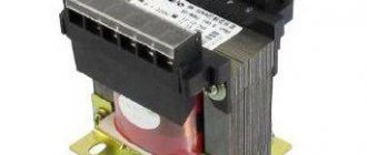
The distributor consists of three blocks. The first contains a device that receives high voltage, the second compartment contains a transformer, and the third contains an output for electricity with specified characteristics. There is only one switch. There is a disconnector at the input.
The connection of the primary windings is carried out according to the star circuit. The zero phase must be grounded. The secondary windings are connected in the form of a triangle. One of the phases is grounded and connected to the rail. The metro has a special contactor for this purpose. This rail is intended solely for relieving the stress of an electric locomotive.
The other phases supply current to the two overhead cables. They are sometimes used to supply electricity to other consumers, but mainly traction substations provide power to trolleybuses via overhead wires. For a tram, this process involves one overhead wire and one ground rail. In most countries of the world, the voltage for such a network is 550 V.
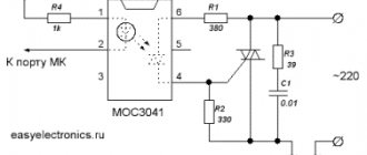
What does the block diagram look like?
Structural scheme
There are several most common connection methods, depending on what loads are planned to be supplied and what type of objects will be connected. As a result, the composition of the equipment may change.
The figure shows one of the simplest options. The switchgear includes three cells, and the design provides only one switch. Only one disconnector is installed at the input, which also helps to simplify the circuit. There is no need to use backup equipment. Considering the differences in equipment such as a mast-mounted transformer substation, the diagram will look slightly different.
Recommendations for selection
The main criterion for the effectiveness of using a particular type of installation is the compliance of the parameters with the operating conditions, in particular, the level of the supplied load. If a traction or pole transformer substation is selected, its typical design implies the need to perform the following actions:
- Selection of connection diagram and connection of main components;
- Determination of the most suitable option for current-carrying devices and components;
- Based on the calculated values of electrical parameters, the main components of such equipment (switchgears, transformers, switches, disconnectors, protection elements, charging batteries) are selected.
Similar actions are performed in the case when a mast transformer substation is selected; a typical project will also largely consist of a calculation part.
Installation nuances and regulatory documentation
The main feature of the principle of installation of equipment used to power railway electric transport is that all work is carried out with the direct participation of electrical installation trains. The list of key tasks includes the installation of the traction substation itself, and at the same time the sectioning posts, telemechanical equipment and contact network. Equipment such as pole-mounted transformer substations are connected in a slightly different way, given that all the main components are mounted on a support.
STN TsE 12-00 “Standards for the production and acceptance of construction and installation work during the electrification of railways” define a number of requirements for the installation of such equipment. For comparison, a mast-mounted transformer substation involves preparing a pit for installing a support, checking the accuracy of the installation using plumb lines, installing the main components on the supporting structure, and connecting all elements.
Thus, traction units are distinguished by a variety of designs, which, on the one hand, somewhat complicates the choice of such equipment, and on the other, allows you to choose the most suitable option. But pole-mounted transformer substations are equipment for a narrower purpose and represent a dead-end design option for a certain range of power values and voltages. When choosing any of these types of equipment, the level of load withstand, the connection diagram, as well as the compliance of the main parameters with the operating conditions are taken into account.
Substation power supply
The traction substation must provide an uninterrupted supply of electricity for vehicle movement. Therefore, many of these units are powered from two autonomous networks at once. In this case, a single-line diagram of a traction substation can be used or using two backup lines to another power source. It is also possible to supply power via jumpers between individual substations.
If the option of two separate lines is used, each of them must be designed for the maximum load of the unit. Redundant communications must be able to withstand the total load of the connected stations.
Previously, a radial circuit was used to power subway networks. It is complex and expensive. It requires too much cable. They refused it. Today, only the above schemes are used. Lines and jumpers allow you to combine equipment into separate groups. If one device inside it fails, other units take over its functions.
Also, when carrying out routine maintenance of units, all operations will be easier, without causing the system to stop. In this case, it is possible to de-energize only one unit. Other devices will ensure the operation of the line. This approach to routine repairs greatly simplifies the work of personnel, making maintenance less expensive.
AC traction substation
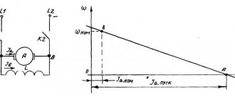
The AC traction substation serves only to reduce the voltage (transformation) of the alternating current received from the power systems. A single-phase current of this voltage powers the contact network. AC traction substations of the 2×25 kV system with a primary voltage of 110 (220) kV have a structural diagram, the peculiarity of which is the use of special single-phase transformers and their connection to the traction network. At AC traction substations, capacitor banks are used. At AC traction substations, in many cases, equipment is installed, the need for which is determined by the type of current and its effect on communication lines and low-voltage electrical networks running parallel to the railway.
Scheme of an AC traction substation.
For this purpose, at traction substations, special installations are used to increase the power factor of the traction load, signaling devices for powering lines with high-frequency current, and compensating devices. At AC traction substations, high-voltage traction voltage cables must be unarmoured and in a non-metallic sheath. In addition, the switchgear must include measures to prevent heating of metal structures by single-phase alternating current.
At 2×25 kV AC traction substations, two working and one backup transformers are installed. Powering traction loads from single-phase transformers assembled according to an open delta circuit forces the installation of additional two or three winding transformers to power regional non-traction consumers.
At combined AC traction substations (for electricity consumers of categories I and II), as a rule, two traction and two separate transformers are installed to power the power load. At AC traction substations built between 1954 and 1961. In auto-blocking power supply circuits at a frequency of 75 Hz, in addition to the listed transformers, autotransformers are installed. In an autotransformer, the low voltage winding is part of the high voltage winding.
The district is powered from alternating current traction substations with a higher voltage of PO kV can be supplied either from three-winding traction transformers or from individual transformers installed at traction substations. If a single supply voltage is required to power the area, the most appropriate power supply circuit is from the third winding of traction transformers. In the presence of an existing district load on two voltages, it may be a more economical option to supply traction and district consumers from separate transformers.
Additional material: How to make a 4G antenna.
The efficiency of a separate power supply scheme increases in cases where it is possible to limit the installation of one transformer to power traction, and also when a traction substation is built near an existing regional substation. The power of transformers STp of AC traction substations depends on the magnitude of the traction load on power arms 1a and /fr and on the power of the railway non-traction S. Due to the high power of AC traction substations, voltages below PO kV are not used to power them. Therefore, when placing such a substation near a district one, it is recommended to place them on the same site.
How does a traction substation work?
Number of units
At power supply points for surface and underground transport, installations with different numbers of devices are used. There are both single-unit and multi-unit structures. The first type is used on branches where there is no need to provide centralized supply. The rationale for their use is questionable, since they do not provide high power reliability. If the unit fails or requires maintenance, the entire line will be de-energized. Therefore, such installations are used quite rarely.
Much more often you can find two-unit power supply units. There are substations with three or four transformers. This significantly increases the reliability of the line. They ensure uninterrupted power supply even in the event of failure or maintenance of one unit.
When the load increases to the maximum, multi-device circuits are highly flexible. This approach makes it possible to reduce the cost of construction and operation of equipment.
Having considered the features and types of traction substations, one can assess the importance of their correct selection and operation in urban and state transport networks.