To measure current, a measuring device called an Ammeter
. Current strength has to be measured much less often than voltage or resistance, but, nevertheless, if you need to determine the power consumption of an electrical appliance, then without knowing the amount of current it consumes, the power cannot be determined.
Current, like voltage, can be constant or variable, and different measuring instruments are required to measure their values. Current is designated by the letter I
, and to the number, to make it clear that this is the current value, the letter
A
. For example, I=5 A means that the current in the measured circuit is 5 Amps.
On measuring instruments for measuring alternating current, the letter A is preceded by the sign “~
“, and those intended for measuring direct current are marked “
–
“.
For example, –A
means that the device is designed to measure direct current.
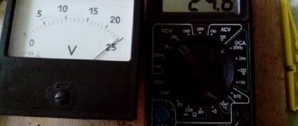
You can read about what current is and the laws of its flow in a popular form in the website article “The Law of Current Strength”. Before taking measurements, I strongly recommend that you read this short article. The photo shows an Ammeter designed to measure direct current up to 3 Amperes.
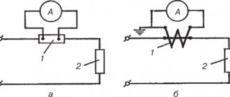
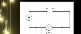
Circuit for measuring current with an ammeter
According to the law, current flows through wires at any point in a closed circuit of the same magnitude. Therefore, in order to measure the current value, you need to connect the device by breaking the circuit in any convenient place. It should be noted that when measuring the current value, it does not matter what voltage is applied to the electrical circuit. The current source can be a 1.5 V battery, a 12 V car battery, or a 220 V or 380 V household power supply.
The measurement diagram also shows how an ammeter is indicated on electrical circuits. This is a capital letter A surrounded by a circle.
When starting to measure the current in a circuit, it is necessary, as with any other measurements, to prepare the device, that is, set the switches to the current measurement position, taking into account its type, constant or alternating. If the expected current value is not known, the switch is set to the maximum current measurement position.
Types of ammeters
While setting in voltage mode is sufficient, the measurement in ammeter mode should be correct, taking into account the slight offset discussed as the current increases. The same adjustment could be made, but without a connected load, then it would be verified that the current measurements are now more accurate, but then the voltage across the load is slightly less.
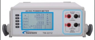
Table of technical characteristics of ammeters of various parameters.
Magnetoelectric devices
Devices that respond to magnetic phenomena (magnetoelectric) are used to measure very small currents in circuits with direct current. There is nothing superfluous inside them, except for the coil, the arrow connected to it and the scale with divisions.
Electromagnetic devices
Unlike magnetoelectric ones, they can also be used for networks with alternating current, most often in industrial circuits with a frequency of fifty hertz. An electromagnetic ammeter can be used for measurements in circuits with high current strength.
Thermoelectric type
Used to measure high frequency alternating current. A heating element (high resistance conductor) with a thermocouple is installed inside the device. Due to the passing current, the conductor heats up, and the thermocouple records the value. Due to the resulting heat, the frame with the arrow deviates at a certain angle.
Based on electrodynamics
Can be used not only for measuring direct current, but also alternating current. Due to the characteristics of the device, it can be used in networks where the frequency reaches two hundred hertz. An electrodynamic ammeter is used mainly as a control meter for testing devices.
They react strongly to external magnetic fields and overloads. Because of this, they are rarely used as meters.
Ferrodynamic devices
Very reliable devices that are highly durable and are little affected by magnetic fields arising outside the device. These types of ammeters are installed in automatic control systems as recorders.
It will be interesting➡ How to choose a soldering iron for microcircuits
It happens that the scale of the device is not enough and it is necessary to increase the values that are worth measuring. To achieve this, shunting is used (a conductor with high resistance is connected in parallel to the device). For example, to set the power value to one hundred amperes, but the device is designed for only ten, then attach a shunt whose resistance value is nine times lower than that of the device.
Interesting read: What is a varistor and where is it used.
How to measure current consumption of an electrical appliance
For the convenience and safety of measuring current consumption by electrical appliances, it is necessary to make a special extension cord with two sockets. In appearance, a homemade extension cord is no different from an ordinary extension cord.
But if you remove the covers from the sockets, it is not difficult to notice that their terminals are connected not in parallel, as in all extension cords, but in series.
As you can see in the photo, the mains voltage is supplied to the lower terminals of the sockets, and the upper terminals are connected to each other by a jumper made of wire with yellow insulation.
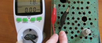
Everything is ready for measurement. Insert the plug of the electrical appliance into any of the sockets, and the ammeter probes into the other socket. Before measurements, it is necessary to set the device switches in accordance with the type of current (AC or DC) and to the maximum measurement limit.
As can be seen from the ammeter readings, the current consumption of the device was 0.25 A. If the device scale does not allow direct reading, as in my case, then it is necessary to calculate the results, which is very inconvenient. Since the ammeter measurement limit is 0.5 A, to find out the division value, you need to divide 0.5 A by the number of divisions on the scale. For this ammeter it turns out 0.5/100=0.005 A. The needle has deviated by 50 divisions. So now you need 0.005×50=0.25 A.
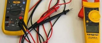
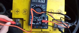
As you can see, taking current readings from pointer instruments is inconvenient and you can easily make a mistake. It is much more convenient to use digital instruments, such as the M890G multimeter.
The photo shows a universal multimeter turned on in the AC current measurement mode to a limit of 10 A. The measured current consumed by the electrical device was 5.1 A at a supply voltage of 220 V. Therefore, the device consumes 1122 W of power.
The multimeter has two sectors for measuring current, designated by the letters A–
for direct current and
A~
for measuring alternating current. Therefore, before starting measurements, you need to determine the type of current, estimate its magnitude and set the switch pointer to the appropriate position.
Multimeter socket labeled COM
is common to all types of measurements.
Sockets marked mA
and
10A
are intended only for connecting a probe when measuring current. For a measured current of less than 200 mA, the probe plug is inserted into a mA socket, and for a current of up to 10 A, into a 10 A socket.
Attention, if you measure a current that is many times greater than 200 mA when the probe plug is in the mA socket, the multimeter can be damaged.
If the value of the measured current is not known, then measurements should be started by setting the measurement limit to 10 A. If the current is less than 200 mA, then switch the device to the appropriate position. Switching multimeter measurement modes can only be done by de-energizing the circuit being measured.
.
Shunt design and connection
To connect the ammeter, use a standard shunt, which is a copper plate mounted on a carbolite insulator. There are two screws on each side of the copper plate: potential and current clamps. The kit includes factory products that have a set resistance and are designed for a certain current.
analog ammeter
To correctly include the shunt in the measurement circuit, adhere to the following algorithm:
- You should choose a product with large expected values. For example, if the estimated current strength in the line being tested is 12–15 A, a product is selected that allows measurements to be taken up to 20 A;
- Next, the measuring wires from the ammeter are connected to the potential terminals on the copper strip;
- The measured line is de-energized;
- Then disconnect the power wires from the device on which you want to check the consumption value;
- The shunt is connected to a break in the electrical line: the disconnected wires are connected to the current clamps.
Now the power is turned on and readings are taken from the ammeter. After this, the line is de-energized again, the measuring device is turned off, and the connections are restored.
Note! The readings obtained are multiplied by the coefficient indicated on the shunt insulation plate. If this coefficient is not specified, you can independently calculate the price of the device division. To do this, the maximum scale value is multiplied by the calculated indicators of the additional plate.
Calculation features
If there are no standard shunts with factory designations, these values can be calculated independently if you use industrial resistors instead of resistance. In this case, proceed as follows:
- To expand the range of the measurement scale, a resistor is connected in parallel to the device, through which the main part of the current passes. In this case, a small part passes through the measuring device, sufficient for measurements;
- The next step is to determine the maximum current value. To do this, a voltmeter, observing polarity, measures the voltage at the power source. The total resistance of the circuit is also determined, by which the voltage value is divided;
- Now you need to find out the resistance of the ammeter winding. This value is indicated in the passport for the device or measured independently;
- It remains to calculate the required resistance of the resistor used as a shunt. To do this, the maximum current is multiplied by the total line resistance, and the resulting value is divided by the rated voltage of the power source.
Now you know not only how, but also how to properly connect it to an electrical circuit. We hope that this material helped you get out of the situation where the measuring scale of the device is not enough for accurate measurements. We figured out that for this you need to connect a standard shunt or calculate it yourself. To determine the current value in an electrical circuit, special devices are used - ammeters.
It might be interesting➡ How to connect an ammeter to an AC or DC circuit
The ammeter is connected in series to the circuit under study, and, due to its extremely low internal resistance, this measuring device does not make any significant changes to the electrical parameters of the circuit. The instrument scale is graduated in amperes, kiloamperes, milliamperes or microamperes. To extend the measurement range, the ammeter can be connected to the circuit through a transformer or in parallel with the shunt, when only a small fraction passes through the device, and the main current of the circuit flows through the shunt.
Interesting read: what are klystrons.
Ammeter full scale gain
The magnitude of the repulsion force and, consequently, the amplitude of the needle movement depends on the amount of current flowing through the coil. It was previously reported that the scope of any instrument can be expanded. In the case of an ammeter, a device called a shunt is used for this purpose.
This allows it to pass only through the moving coil of the device, a current that it can tolerate. The shunt is formed by a pressure resistance of an ohmic value lower than the reading of the moving coil of the device, which allows the passage of another portion of the current that is not allowed.
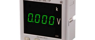
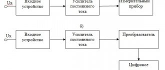
Digital ammeter
In order to determine the voltage at the terminals of the energy receiver or generator using the readings of a voltmeter, it is necessary to connect its terminals to the terminals of the voltmeter so that the voltage at the receiver (generator) is equal to the voltage at the voltmeter. The resistance of the voltmeter must be large compared to the resistance of the energy receiver (or generator) so that its inclusion does not affect the measured voltage (the operating mode of the circuit).
Connecting an ammeter via a shunt
If the device is connected directly to the measuring circuit, without a current transformer, it is called a direct-connection ammeter.
Without a shunt, you can use devices designed for low current, on the order of milliamps. By shunting the measuring winding with a resistance greater than its own, we can change the measurement limit. The connection circuit is no different in complexity: the measured current passes through the shunt, and an ammeter is connected in parallel to it.
This is where Kirchhoff's first law comes into play. The measured current is divided into two: one flows through the frame, the second through the shunt.
They will relate to each other like this:
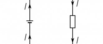
Ammeter connection diagrams
Figure - Diagram of direct connection of an ammeter
Read also: Content of precious metals in reed switches
Figure - Scheme of indirect connection of an ammeter through a shunt and a current transformer
Ammeter device
To understand the need to turn on the ammeter through a shunt, let us briefly recall its structure.
Inside the field of a permanent magnet there is a coil - a frame. The measured current flows through its turns. Depending on the value of the measured parameter, the position of the coil relative to the constant magnetic field changes. The arrow of the device is rigidly fixed on its axis. The greater the current being measured, the more the needle deflects.
So that the frame can rotate, its axis is secured in the thrust bearings, or hung on guy wires. When using thrust bearings, the frame current passes through spiral springs, but if the moving part of the device is suspended on guy wires, then they are current conductors.
From this design it follows that the amount of current in the frame is structurally limited. Springs and extensions cannot simultaneously be sufficiently elastic and have a large cross-section.
How to determine the accuracy class
According to current state standards, ammeter manufacturers are required to guarantee its relative measurement error, obtained according to the accuracy class indicated on the measuring panel and in the device passport. In addition, all measuring instruments must undergo periodic verification at metrological centers to ensure compliance with the factory accuracy class. If it does not pass such certification, it cannot be used in measurement processes.
Knowing the absolute error and the current reading on the scale, you can simply obtain the real current acting in the circuit. In this case, the scale for applying the absolute error is considered uniform.
Important! When choosing a dial ammeter scale, it is necessary that the operating current value is approximately 2/3 of the scale range. If the needle is almost at 0 or at the maximum scale reading, then the relative error will be very high, that is, it is not recommended to trust such readings.
What is the difference between an ammeter and a galvanometer?
Ammeter
- a device designed to measure the strength of direct and/or alternating electric current.
A galvanometer
is a highly sensitive device for measuring small currents, voltages and charges.
Interesting materials:
How to access a deleted page in a contact? How to understand that you have been removed from contacts in Viber? How to view other people's deleted posts on Instagram? How to view a photo from a deleted page in contact? How to view the cache of a remote site? How to see who deleted a message on Instagram? How to view a message on VK that has been deleted? How to watch a deleted Instagram video? How to watch a deleted video on Viber? How to view deleted iPhone history?
EXPANDING THE MEASUREMENT LIMITS OF AMPERMETER AND VOLTMETER
LESSON OBJECTIVE: To consolidate the knowledge acquired by students in previous lessons. Introduce students to ways to expand the measurement limits of an ammeter and voltmeter.
TYPE OF LESSON: combined.
EQUIPMENT: rectifier VS-24, ammeter and demonstration voltmeter with shunts and additional resistances, laboratory voltmeter, ampere-voltmeter, connecting wires.
LESSON PLAN: 1. Introductory part 1-2 min
3. Explanation 15 min
4. Fixing 10 min.
5. Homework assignment 2-3 min
II. Fundamental question: 1. Series and parallel connection of resistors. 2. Mixed connection of resistors.
1. A radio amateur needs a resistor with a resistance of 70 kOhm. He found three resistors with resistances of 100 kOhm, 50 kOhm, and 25 kOhm. Can he use them to create the required resistance?
2. There is a current source with a voltage of 6 V, a rheostat with a resistance of 30 Ohms and two light bulbs on which it is written: 3.5 V, 0.35 A and 2.5 V, 0.5 A. How to assemble a circuit so that the light bulbs work normally mode? What should the rheostat resistance be?
Adjustment of the measuring system
For the manufacture of factory products, materials are used that do not change their characteristics over a wide temperature range. Therefore, the best option is to select a ready-made shunt and adjust it for your purposes by reducing the cross-section and length of its conductor to match the calculated value. But to make a shunt for an ammeter, you can also use improvised materials: copper or steel wire, even paper clips will do.
Now you need a power supply with a voltage regulator to deliver the required current. For the load, you can use a resistor of appropriate power or incandescent lamps.
First, we achieve compliance with the total deflection of the instrument needle at the maximum value of the measured value. At this stage, we select the resistance of our homemade product to the maximum possible coincidence with the final mark on the scale.
Then we check whether the intermediate risks coincide with their corresponding values. If not, we disassemble the ammeter and redraw the scale.
And when everything worked out, we install the finished device in its place.
An example of finding an ammeter reading from the given error
For example, we consider an analog meter with a scale of up to 25 A.
The scale has a designation of accuracy class 2.5, there is no circle or square, so this error is given.
Y=Dх/Xп×100=+/- p
At Xp = 25A and p value = 2.5, the absolute error can be calculated:
Δх =25/100×2.5=0.625 A
If the user finds an accuracy class enclosed in a square on the panel, then the error will need to be determined as a percentage of the measured value.
With scale readings Ii = 10 A, the instrument error should not exceed
Δх =10×2.5/100=0.25
When reading on a scale Ii = 2 A, the error will be different:
Δх =2×2.5/100=0.05
When reading on a scale Ii = 25 A, the error will be maximum:
Δх =25×2.5/100=0.625
This is why it is important that an analog instrument operates at 2/3 of the operating scale.