Independently excited motor
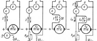
In a DPT with independent excitation, the excitation winding is connected to a separate power source (Fig. 1). This may be due to different excitation voltages Uв and armature circuit voltage U. With this connection diagram, the OB has no electrical connection with the armature winding. To reduce losses in the OF and create the necessary MMF, it is necessary to reduce the excitation current by increasing the number of turns. The field winding is made of a small number of turns, so that the current Iв is 2...5% of Iа. The choice of this excitation circuit for the motor depends on the properties of the electric drive.
Speed control by weakening magnetic flux
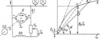
Speed control by weakening the magnetic flux is usually carried out using a rheostat in the excitation circuit Rр.в (see Figure 1, b in the article “General information about DC generators” and Figure 1 in the article “Starting DC motors”). In the absence of additional resistance in the armature circuit (Rpa = 0) and U = const, the characteristics n = f(Ia) and n = f(M), determined by equalities (7) and (9), presented in the article “General information about DC motors” current", for different values of Rр.в, iв or Фδ have the form shown in Figure 2. All characteristics n = f(Ia) converge on the abscissa axis (n = 0) at a common point at a very large current Ia, which, according to expression (5) presented in the article “General information about DC motors” is equal to
Ia = U / Ra.
However, the mechanical characteristics n = f(M) intersect the x-axis at different points.
The lower characteristic in Figure 2 corresponds to the nominal flow. The values of n under steady-state operating conditions correspond to the points of intersection of the characteristics under consideration with the curve Mst = f(n) for the working machine connected to the engine (thick dashed line in Figure 2).
The engine idle point (M = M0, Ia = Ia0) lies slightly to the right of the ordinate axis in Figure 2. With increasing rotation speed n due to increased mechanical losses, M0 and Ia0 also increase (thin dashed line in Figure 2).
If in this mode, using an externally applied torque, we begin to increase the rotation speed n, then Ea [see expression (6) in the article “General information about DC motors”] will increase, and Ia and M will, according to equalities (5) and (8), presented in the article “General information about DC motors”, decrease. At Ia = 0 and M = 0, the mechanical and magnetic losses of the engine are covered by the mechanical power supplied to the shaft, and with a further increase in speed, Ia and M will change sign and the engine will switch to the generator mode of operation (characteristic sections in Figure 2 to the left of the ordinate axis).
Motors for general use allow, according to switching conditions, speed control by field weakening within the range of 1: 2. Motors with speed control in this way within the range of up to 1: 5 or even 1: 8 are also manufactured, but in this case, to limit the maximum voltage between the collector plates, it is necessary to increase air gap, regulate the flow across individual groups of poles (see the article “Regulation of rotation speed and stability of operation of DC motors”) or use a compensation winding. This increases the cost of the engine.
DBT with mixed arousal
DPT with mixed excitation (Fig. 4) has two OBs, one of which is connected in series, and the other in parallel to the armature circuit. When the windings are connected in a consistent manner, as the load on the shaft increases, the magnetic flux increases, which leads to a decrease in the rotation speed. With a counter connection, the total magnetic flux decreases with increasing load, which leads to a sharp increase in rotation speed. This leads the engine to an unstable operating mode, so the series winding is made of a small number of turns so that when the load increases, the magnetic flux decreases slightly, thereby stabilizing the operation of the engine.
2.77 (13 Voices)
- Forward
Natural speed and mechanical characteristics
Let us consider in more detail the characteristics of a parallel excitation motor, which determine its operating properties.
The speed and mechanical characteristics of the motor are determined by equalities (7) and (9), presented in the article “General information about DC motors”, with U = const and iв = const. In the absence of additional resistance in the armature circuit, these characteristics are called natural .
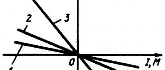
If the brushes are at a geometric neutral, with an increase in Ia, the flux Фδ will decrease slightly due to the action of the transverse reaction of the armature. As a result of this, the speed n, according to expression (7), presented in the article “General information about DC motors,” will tend to increase. On the other hand, the voltage drop Ra × Ia causes a decrease in speed. Thus, three types of speed characteristics are possible, shown in Fig. 1: 1 – when the influence of Ra × Ia predominates; 2 – with mutual compensation of the influence of Ra × Ia and a decrease in Фδ; 3 – when the influence of decreasing Фδ predominates.
Due to the fact that the change in Фδ is relatively small, the mechanical characteristics n = f(M) of a parallel-excitation motor, determined by equality (9), presented in the article “General information about DC motors”, with U = const and iв = const, coincide in appearance with characteristics n = f(Ia) (Figure 1). For the same reason, these characteristics are almost straightforward.
| Figure 1. Types of natural speed and mechanical characteristics of a parallel-excitation motor |
Characteristics of type 3 (Figure 1) are unacceptable under the conditions of stable operation (see the article “Regulation of rotation speed and stability of operation of DC motors”). Therefore, parallel excitation motors are manufactured with slightly falling characteristics of type 1 (Figure 1). In modern highly used machines, due to the rather strong saturation of the armature teeth, the influence of the transverse reaction of the armature can be so large that it is impossible to obtain a characteristic of type 1 (Figure 1). Then, to obtain such a characteristic, a weak series excitation winding of consonant inclusion is placed at the poles, the magnetizing force of which is up to 10% of the magnetizing force of the parallel excitation winding. In this case, the decrease in Фδ under the influence of the transverse reaction of the armature is partially or completely compensated. Such a series field winding is called stabilizing , and a motor with such a winding is still called a parallel field motor.
The change in rotation speed Δn (Figure 1) during the transition from idle (Ia = Ia0) to the rated load (Ia = Ian) for a parallel-excitation motor when operating at a natural characteristic is small and amounts to 2–8% of nn. Such weakly decreasing characteristics are called hard. Parallel excitation motors with rigid characteristics are used in installations in which it is required that the rotation speed remains approximately constant when the load changes (metal-cutting machines, etc.).
| Figure 2. Mechanical and speed characteristics of a parallel-excitation motor at different excitation flows |
Advantages and disadvantages
Among the advantages of combined engines it is worth highlighting:
- high adjustment rates;
- good level of torque even at low engine speeds;
- accuracy of adjustment, low probability of getting out of control;
- minimal loss of magnetism over time;
- almost linear and mechanical adjustment parameters that provide ease of use;
- a high level of starting torque, which contributes to the quick start of a motor with such a drive. Moreover, in any environmental conditions;
- compact dimensions. This feature especially concerns the designs of devices with permanent magnets;
- the possibility of using a single mechanism to operate in generator and engine modes;
- The efficiency factor when operating at maximum loads is on average 1-3% higher than that of power units of synchronous and asynchronous design types. If the load is partial, then the figure can increase to 15%.
As motor designs improve, their benefits expand as well.
There are also disadvantages, the main one worth highlighting is the high market value compared to other modifications. Maintenance also costs an order of magnitude higher, because it is necessary to prevent wear of structural parts more often. Although modern engineering solutions help correct these shortcomings.
Performance characteristics
The operating characteristics represent the dependences of power consumption P1, current consumption I, speed n, torque M, and efficiency η on the useful power P2 at U = const and constant positions of the control rheostats. The operating characteristics of a low-power parallel excitation motor in the absence of additional resistance in the armature circuit are presented in Figure 5.
Simultaneously with the increase in power on the shaft P2, the torque on the shaft M also increases. Since with an increase in P2 and M the speed n decreases somewhat, then M ∼ P2 / n grows somewhat faster than P2. An increase in P2 and M is naturally accompanied by an increase in motor current I. The power P1 consumed from the network also increases in proportion to I. At idle (P2 = 0), the efficiency η = 0, then with an increase in P2, at first η quickly increases, but at high loads, due to the large increase in losses in the armature circuit, η begins to decrease again.
Source: Woldek A.I., “Electrical machines. Textbook for technical schools" - 3rd edition, revised - Leningrad: Energy, 1978 - 832 p.
Design Features
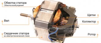
An electric motor operating from a network with a constant current value (DC), like an asynchronous or synchronous motor with a variable power supply voltage, contains two main blocks: a stationary stator (or inductor) and a rotating armature (or rotor). The stator ensures the formation of the main magnetic field. Its block diagram contains:
- frame made of cast steel;
- main poles that form the main magnetic field;
- additional poles ensuring good switching.
The steel frame serves as a reliable base for the electric motor, on which all fixed elements are mounted. It also acts as a structural link in the magnetic circuit. The main pole consists of a laminated core, bolted to the base, and chain coils. It is made in bulk or assembled from electrical steel. To form the required distribution of magnetic field lines, the core is equipped with a pole piece. In some places, a DC motor is produced with distributed compensation electrical wires placed in the grooves of the cores.
The electrical circuits of the main pole are structurally made in the form of lumped coils and can be powered either from a network source or from the clamps of the armature winding. DC motors with a central connection to the power supply are independent excitation DC motors. The additional poles, like the main ones, contain lumped induction coils and a core made in the form of a massive solid product.
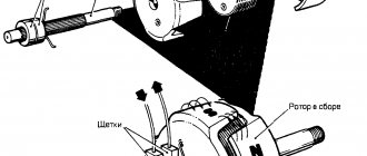
The design of the moving part of the electric drive – the armature – provides for the use of:
- a gear core made of sheet electrical steel;
- a collector assembled from wedge-shaped copper plates isolated from each other.
The electrical circuit of the rotor and commutator mounted on the rotor shaft fits into the grooves on the front surface of the gear core. The collector mechanism is a hollow cylindrical product. The connection of the armature wires to the collector block is made to each copper plate by the two ends of separate parts of the rotor electrical winding.
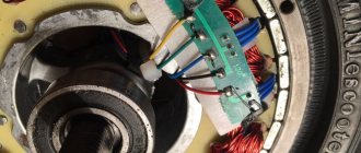
On the commutator, in brush holders, fixed brushes are placed, through which the rotor conductors are connected to the central electrical circuit. This ensures independent excitation of the traction motors. The brush holder is a brush apparatus with a traverse on which the brush fingers are attached. The traverse is attached to the stationary part and allows rotation at a certain angle around the shaft axis to adjust the position of the brushes.
Brushed DC motors are symmetrical and have either a vertical or horizontal axis of symmetry. The first one runs in the middle of the main poles, the second - in the interpolar space. The transverse axis is called the geometric neutral of the drive unit.
There is another type of electric motor - a valve-drive mechanism or a brushless electric drive. Its difference lies in the replacement of the brush-collector assembly with a semiconductor switch. This allows you to obtain practical advantages: high efficiency, reliability, wide power range, fire safety.