Simple ATS circuit for 2 inputs
The simplest ATS circuit for two single-phase inputs is assembled on just one magnetic starter. To do this you will need a contactor with two pairs of contacts:
- normally open
- normally closed
If your contactor does not have these, you can use a special attachment.
Just keep in mind that the contacts of most of them are not designed for high currents. And if you decide to connect the load of the entire house through the ATS, then you certainly shouldn’t do this using the block contacts located on the sides of standard starters.
For these purposes, it is better to choose equipment that initially has power closed and open contacts in its design. Suitable brands are VS 463-33 or ESB-63-22, MK-103 from DeKraft, KM IEK.
Here is the simplest AVR diagram:
Generator connection. Options for ATS circuits for a generator
I’ll say right away that the generator has nothing to do with it, in this case it’s just a backup power source. This source can be not only a generator, but also a second phase, and a phase from another substation or another line. Automatic transfer switch (ATS) schemes are universal and can work in different situations.
Basically, what is there to connect here? The generator has a regular socket, a plug is included, what are the problems? But where does the wire from the plug go? And how can you make sure that the connection diagram is convenient, correct, and most importantly, safe?
The most dangerous thing about connecting a generator is when the voltages from the generator and from the city meet. Or the voltage from the generator will go to the city, where a crew is working on the line in full confidence that the network is de-energized.
It would seem that it would be easier to install a switch, and there would be no problems.
1. Generator connection diagram via switch
At the end of the article there is a photo with an example of such a switch.
This is what many people do, and this is what I do, depending on the client’s financial capabilities. Just don't forget about two important things:
- Do not shift under load!
- Select the correct protection and current of the circuit breaker (switch).
But we are not looking for easy ways, give us automation and protection from accidents and the human factor.
Therefore, I propose to consider the second version of the scheme:
2. Connection diagram of the generator via a voltage control relay. The simplest scheme.
The second circuit uses a KV voltage control relay. In fact, this is an ordinary relay that is in the on state when the voltage from the city is normal. And the changeover contact will be in the left position according to the diagram.
When the voltage from the city disappears, the relay turns off, and the circuit takes on the form shown - the load is powered by the generator.
The voltage control relay is the basis of any ATS circuit. For single-phase circuits, this is a regular relay that is powered from the main phase.
For three-phase circuits, a three-phase phase control relay is used, which is described in detail in my other article.
Let's go further and improve the ATS circuit for automatically connecting the generator:
3. Connection diagram of the generator via relays and contactors. AVR with amplification
The third circuit differs from the second in that it can pass a much larger current through itself. The KV voltage relay is used only for its intended purpose - it switches the load, supplying power to the coil of the corresponding starter.
When there is voltage from the city, KV is turned on, it turns on the KM1 contactor with its normally open (NO) contact, and phase L1 is supplied to the load (circuit output L).
When the voltage from the city stops coming, KV turns off, and with its NC contact it turns on the KM2 contactor, and phase L2 is supplied to the load.
The scheme is excellent, and even working. But using it is extremely dangerous. Due to the lack of protection against short circuit “phase L1 to phase L2”. Such a short circuit can occur due to a malfunction (sticking contacts, jammed relays or contactors), or due to the notorious human factor - what if a collective farm electrician decides to press the KM2 starter when KM1 is turned on?
According to statistics, in the case of the correct attitude to planned preventive maintenance, 90% of malfunctions and accidents occur due to the human factor!
So, in order to reduce the likelihood of accidents by an order of magnitude, in practice the following ATS scheme is used:
4. Circuit with electrical and mechanical interlocks
The only difference between it and scheme 3 is that it includes protection against the simultaneous activation of contactors KM1 and KM2. The protection has two stages - electrical and mechanical.
Electrical interlocking is implemented on the NC contacts KM1 and KM2, which mutually exclude the simultaneous activation of starters.
And the mechanical one (indicated in the diagram by an inverted triangle) is provided by the design of the starters. The starter in this case must be reversible; read more in the article about the circuit diagram for connecting a reversible starter.
Well, the practical diagram that I put together will look like this:
5. ATS diagram for connecting a generator with interlocks and protections
Two-pole circuit breakers QF1 and QF2 were added, as well as a power contact that breaks the neutral wire N1 in the event of a city shutdown.
Tearing the “city” zero is necessary for additional security. The fact is that at the output of the generator there is no concept of “working zero” and “phase”, and they can be called that way conventionally. And in the event of a stuck “phase” contact, when the N1 zero is not broken (as in diagram 4), a voltage of 220V will flow into the city line.
This is the diagram I put together, now I’ll show you how.
Description and principle of operation
The magnetic starter coil is connected to one of the inputs. In normal mode, voltage is supplied to the coil, it closes contact KM1-1, and contact KM1-2 opens.
SF1 and SF2 in the circuit are single-pole circuit breakers.
The voltage is supplied to the consumer through the contactor. Additionally, signal lamps can be connected to the circuit. They will visually show which of the inputs is currently connected. Slightly modified diagram with light bulbs:
If the voltage at the first input disappears, the contactor is removed. Its contacts KM1-1 open, and KM2-1 close. Voltage begins to flow to the consumer from input No. 2.
If you just need to check the functionality of the circuit in normal mode, then turn off the SF1 machine and watch how the assembly reacts. Is everything working properly?
The most important thing here is to initially check what current these normally closed and open contacts are designed for.
Please note that this simple circuit can be assembled in two ways:
- without zero break
- with a break in the neutral wire
Checking work
That's all, you can check it.
We turn off the house so as not to disturb consumers. We turn off the input machine from the street. Nothing happens for some time (the ATS is smart, it knows that sometimes shutdowns happen for 1-2 seconds, and you shouldn’t react to them). Then the generator starts, and after a few seconds the starter of the automation unit turns on, through which the generator power is supplied to the house. We turn on the introductory street machine. The generator is turned off, the home electrical network is connected to power from the street.
Press the Manual/Auto button until it is “released”. The generator starts, the ATS switches the house to power from the generator. In this case, the generator operates regardless of whether there is voltage on the street line or not.
We move the switch to the “Auto” position, the generator stops if there is street voltage. Or it continues to work if there is no voltage coming from the street.
Job is done. Now the owner can safely go on a business trip, and his family will definitely not be left without electricity.
Reserve input circuit with zero break
Without a break, it can be used if you have two independent power lines or cable inputs, from which you actually connect the entire house. But when the backup line is some kind of autonomous energy source - a UPS or a generator, then you will have to break both the phase and the neutral.
Since the main network in 90% of cases is made with a solidly grounded neutral, and from a generator or UPS it comes with an isolated one. Here it is impossible to combine the zero working conductor from the network with the zero from the generator.
Naturally, all contactors are connected after the kWh meter. QF are modular circuit breakers in a home panel.
If you have a second power source that does not supply voltage automatically, for example, a gasoline generator without starting equipment. Which must first be manually started, warmed up and only then switched, then the circuit can be slightly changed by adding one single button.
Due to this, automatic switching will not occur. You choose the right moment for this by pressing it when needed. This button SB1 is mounted parallel to the contactor coil.
When the voltage at the main input does not disappear for a long time, but periodically disappears and appears (the reasons may be different), in this case it is not advisable to constantly switch the contactors back and forth. Here it is advisable to use a special attachment to a PVI-12 type contactor with a time delay.
Simple automatic transfer systems
The simplest ATS circuit is shown in the figure below:
This circuit uses an electromagnetic relay or contactor K1 with one changeover contact. Typically, this scheme is used in single-phase networks with a small load current. In this circuit, the relay coil is powered from the main input, and in normal mode its core is attracted, the left contact K1 in the diagram is closed, the right one is open. When the voltage at the main input is lost, the relay coil releases the core, the left contact opens, and the right one becomes closed. Power to the load comes from the reserve input.
This simplest scheme has many disadvantages and is usually not used in this form. The main reason is that with significant fluctuations in the voltage in the network, the relay will switch frequently, which is unfavorable both for the relay itself and for the electrical appliances that are powered. In the future, more complex and more reliable ATS schemes will be considered.
The circuit for automatically switching on the reserve presented below, unlike the previous ones, is more applicable and is already suitable for the power supply system in a private house or part of it; the switched load may well be tens of kilowatts:
This scheme eliminates the previous shortcomings, and it can be recommended as a basic one for use in houses, cottages, administrative and industrial buildings with a power consumption of up to 100 kW.
The power supply circuit described below is extremely simple. It can be used to supply electricity to households with low power consumption, on the order of several kilowatts.
Here's the diagram:
Let's analyze it in detail. In working condition, the SA1 and SA2 machines are turned on. If present at the main input, power is supplied to K1, its contact K1.1 is closed, and consumers receive power through it. If the voltage disappears, relay K1 is de-energized, K1.1 opens, and K1.2, on the contrary, closes. The circuit is ready to be powered from a backup source and, if there is voltage on it, the supply of electricity to consumers is resumed.
For K1, you need to choose a powerful relay, which is quite scarce. Usually relays are offered for switching current up to 16A. For high currents, you can take a contactor as K1, but not just any one; it must have a breaking (in common parlance “normally closed”) power contact. Therefore, this circuit is proposed for low-power, up to 16A, connections. If the relay has several contact groups, then you can parallel them, but this is rarely done; usually for high currents a circuit with a reversing starter or triacs is used. In industry, more complex schemes are used - the time will come, we will also consider them.
The disadvantages of this scheme include the fact that the K1 coil is turned on before the meter, which the energy supplier may not like, but this can be easily eliminated by moving the meter higher in the scheme, this will be taken into account further, let the error remain here as a reminder.
A circuit without these disadvantages will be shown below. Here, too, a contactor with breaking power contacts could not be avoided.
The proposed circuit based on a 2z+2p contactor type VS463-22 allows its use at currents up to 63A:
The scheme is cheap and simple; it corrects the shortcomings of the previous scheme:
The circuit uses a VS463-22-230 contactor. Here, unlike the previous scheme, both phase and neutral wires are switched, which prevents current from the generator from entering the network. One closing contact K1.1 is connected before the coil, which will not allow the contactor to turn on spontaneously when voltage reappears at the main input after shutdown. When voltage appears at the main input, in order to re-energize from it, you need to briefly press the SB1 button, after which the contactor will turn on and close contacts K1.1 and K1.2, at the same time opening K1.3 and K1.4.
If the voltage at the main input fails, K1.1 and K1.2 are switched off, and power is supplied to the house from the reserve through K1.3 and K1.4. Some autonomous source of electricity is used as a reserve, so it is connected without going through the meter. If the backup source is configured so that it automatically turns off when power is restored at the main input, then the circuit needs to be changed - remove the SB1 button, and move K1.1 lower in the circuit, into the phase wire gap immediately before Q1, and power the coil directly to the meter outputs . However, such a circuit with a circuit for starting a backup generator will soon be published in a separate article.
Let me add that the coil consumes about 5 Watts, the contactor costs about 2500 rubles.
ATS circuit for 2 starters
The second scheme is a little more complicated. It already uses two magnetic starters.
Let's say you have two three-phase inputs and one consumer. The circuit uses magnetic starters with 4 contacts:
- 3 normally open
- 1 normally closed KM1
The starter coil KM1 is connected through phase L3 from the first input and through the normally closed contact KM2. So when you apply power to input #1, the coil of the first starter is closed and the entire load is connected to voltage source #1.
The second contactor is turned off, since the normally closed connector KM1 will be open at this moment, and power will not be supplied to the coil of the second starter. When the voltage disappears at the first input, contactor-1 disappears and contactor-2 turns on. The consumer remains with the light.
The main advantage of these schemes is their simplicity. The downside is that such assemblies can be called automation schemes with a very big stretch.
As soon as the voltage disappears in the phase that powers the switching coil, you can easily get a counter short circuit.
You can, of course, improve the entire system by choosing a contactor coil not for 220V, but for 380V. In this case, control will be carried out in two phases.
But you still won’t protect yourself 100%. And if you take into account the moment of possible sticking of contacts, then even more so.
In addition, you will not be protected in any way from too low voltage. Starter No. 1 can turn off only if U at the input is below 110V. In all other cases, your equipment will continue to receive low-quality electricity, although it would seem that there is a second serviceable input nearby.
To increase reliability, you will have to complicate the circuit and include additional elements in it:
- voltage relay
- phase control relay, etc.
Therefore, recently, to assemble ATS circuits, special relays or controllers—the “brains” of the entire device—have increasingly begun to be used. They can be from different manufacturers and perform the function of not only turning on backup power from one source.
Suddenly you are faced with a more difficult task. For example, it is necessary for the circuit to control two inputs at once and, in addition, a generator. Moreover, the generator should start automatically.
The working algorithm here is as follows:
1.If input No. 1 is faulty, automatic switching to input No. 2 occurs. 2. If there is no voltage at both inputs, the generator starts and the entire load is switched to it.
ATS connection diagrams and their descriptions
The main function of the ATS is to automatically switch inputs, and in such a way as to eliminate counter currents.
A simple diagram in Fig. 4 explains the switching principle.
Contacts KM1 and KM2 are interconnected. After one contact opens, the other closes. They cannot be turned on at the same time.
There are many different schemes for connecting automatic transfer input, but the principle of their construction is always the following: ATS is installed between the input and consumers. Usually after the electric meter. The automatic switchboard itself can be located anywhere, but the principle of its connection is exactly the same. This principle is clearly illustrated by the diagram in Fig. 5.
Rice. 5. Visual diagram of connecting the ATS
A detailed connection diagram for the automatic generator start unit is shown in Figure 6. In the diagram, K1 and K2 are contactors. Numbers in circles indicate terminal numbers. Using this diagram, it is not difficult to connect such a unit yourself.
Rice. 6. Detailed connection diagram for the generator autostart unit (BAG)
A schematic diagram of connecting an ATS for a private house is shown in Fig. 7.
Rice. 7. Schematic diagram
This circuit uses an ASU that provides stable voltage and continuous power supply to the local network.
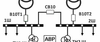
As an example, we present two circuits for three-phase current (Fig. 8). Image B shows a single-sided version (additional PH voltage relay). With this connection, the generator starts automatically after a power outage. In other words, the input from the generator is a backup.
In image A - double-sided design. Both sections have the same priority. This connection allows you to switch lines, regardless of the presence of voltage in each of them.
Rice. 8. Connection of ATS for three-phase current
The choice of scheme depends on the task that you intend to solve.
ATS circuit for 3 inputs with a generator
How and on what basis can such a reserve input be implemented? Here you can use the AVR circuit based on AVR-02 from the FiF Euroavtomatika company.
Today, the cost of such devices is comparable to the price of a good electrical cabinet enclosure from ABB. But there you will get an empty iron box, and here are smart brains that will manage and protect your entire home electrical network.
In principle, it makes sense to spend money once and protect yourself and your equipment once and for all.
Installation of automation (autostart, automatic transfer switch) for generators
Installing an ATS allows you to use the generator without the presence of an operator. This is very convenient when it is not possible to start the generator (gasoline or diesel power plant) manually. The ATS device contains connectors and a logic circuit that switches the network when there is a loss of voltage from the main electrical network and independently (automatically) switches the consumer to the backup generator set and commands the generator to start. The generator starts, warms up and takes on the entire load. When voltage appears in the main network, the AVR unit switches the consumer to the main network, and the generator stops.
AVR-02 reserve input unit
This device is multifunctional and can be used to build 8 different ATS circuits. Three of them are most often used:
- input#1+input#2
- input#1+generator
- input#1+input#2+generator
Let's first consider the most complex one, which has two inputs and a generator. The second input can be either from a separate 0.4 kV overhead line or directly from a cable line from the nearest transformer substation, or assembled on a battery-powered UPS with hybrid inverters.
In this case, in the version with an uninterruptible power supply, it is necessary to provide for a situation when the batteries are discharged to the permissible maximum, and then a switch to the generator occurs. This is very convenient so as not to run the diesel generator during short-term interruptions in the power supply.
What functionality does the AVR-02 have?
- it controls power elements - contactors or starters. Motor drives can also be used.
- controls phase rotation
- controls input synchronization
- generates a generator start signal
- Can be powered by external 12V battery
- measures the voltage level and turns off the faulty line with low or high voltage, automatically transferring power to the one where everything is normal
- generates an emergency signal
On the front panel of the AVR-02 there are:
- two-line liquid crystal display
- navigation buttons
- LED indicators No. 1 and No. 2 – show the connected input
- K1, K2, K3, K4 – state of the executive relays
What is AVR
This is a block consisting of several nodes, which automatically switches the load between the main and backup current sources. Some single-phase and three-phase models of gasoline and diesel generators are equipped with an automatic transfer switch initially. To switch the load, you only need to install a special switch after the electric meter. The position of the power contacts is controlled by the main power source.
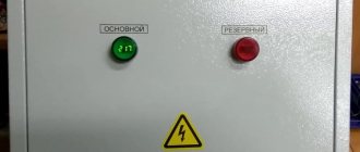
Almost all models with a battery-powered power plant can be equipped with autonomous ATS systems. In this case, ATS cabinets are used to install backup input units. In this case, ATS panels (Figure 1) can be placed directly next to gas generators or the units can be installed in a common electrical panel.
Figure 1. Example of an ATS electrical panel
The main function of the AVR unit is to automatically start the power plant after the disappearance of electric current in the general network, and then connect the load to the backup power supply. When the power supply is restored by the automation unit, the load is switched to the main electrical network, and the backup source is turned off.
Classification of ATS devices:
- by the number of reserve sections;
- voltage class;
- type of backup network (use in single-phase networks or for three-phase consumers);
- power of the served load;
- switching delay time.
The electrical circuit of the ATS can be configured in such a way as to provide energy not to the entire local network, but only to those lines that are critical. Some schemes allow you to take into account the priority of lines. First of all, power is provided to those circuits that provide electricity to important life support systems. This approach allows you to rationally distribute the load.
Operating principle of AVR 02
How does the circuit assembled on the AVR-02 base work? Here are its main elements:
- KM1.1, KM2.1, KM3.1 are the power contacts of the starters
- KV1 – three-phase network monitoring relay
- contacts No. 18,19,20 – are intended for monitoring emergency circuits in motor drives
If a malfunction occurs in the motor drive, voltage is supplied to them and the relay operation is blocked.
- S1 is something like a button with which you can send a signal and forcefully block the operation of the AVR-02
Suddenly you need to carry out some commissioning work. Here you can use the modular option from IEK KMU11.
- SB1 – Reset button
Needed for reset after receiving a signal at contacts No. 18,19,20. Press it and the relay's operation is restored.
- KM4 – intermediate relay
Thanks to its contacts, voltage can be supplied to the coils both from two inputs and from the generator. You can use the RK-1R type.
Let's consider three work algorithms and three situations for this ATS.
Autostart system
At the moment, many devices have appeared with the system already installed in the generator housing; additional manipulations do not have to be performed in order for the gas generator to autostart. But it is necessary to take into account that such a power plant is more expensive. The solution may be to assemble the automatic equipment for the generator yourself. To do this, you must have a control unit (automatic generator start unit).
If we consider the control principle when the system is properly configured , a gas generator with automatic start during a power outage will not require human intervention. For this purpose, a circuit with connection of an automation device is used. The device must be connected to a 12-volt power supply from a battery, the device itself is installed after the meter, for this it will be necessary to install two two-key machines, one for the automation device, the second for the home network. As a rule, there are 4 indicators and a button for switching modes on the ATS panel.
The main power cable is connected to the device ; at the bottom of the device there is a connector for connecting to the generator; it will start the starter when the 220 volt power supply is turned off from the main source. During short outages and network losses, the automation device will not operate, which will prevent the generator from starting idle. If the device does not provide a connection from an ATS, then a battery will be required to start the generator starter with an operating mode switching relay, as well as a throttle controller.
Input No. 1 and Input No. 2 are OK
The first input is the main one, the second one is the backup one. The device, through contacts A1, B1, C1, through the circuit breaker QF2, monitors the voltage at input-1. The same thing happens at input-2, through contacts A2, B2, C2.
Since all these contacts are normal, the AVR-02 should apply voltage to the KM coil. How does this happen?
Contacts 1 and 11 generate a control signal via relay K5. This relay K5, if the voltage level is normal on both inputs, should turn on input No. 1. That is, it is in the same position as in the original diagram. The voltage through it reaches pin 10 and goes to the KM4 coil. This is an intermediate relay. Its contacts are designated KM4.1 and KM4.2
The relay is triggered, closing its contacts and the voltage through them reaches the 22nd contact. Next, the AVR turns on relay K1. Through it and contact No. 24, the phase reaches the switching coil KM1. At the same time, other relays K2, K3, K4 remain open.
Algorithm No. 2 - input No. 1 is faulty
The voltage at input No. 1 has disappeared. AVR-02 sees that there is no voltage on A1, B1, C1, but there is voltage on A2, B2, C2. Therefore, K5 switches to position No. 11.
Next, U from input-2 comes through 11 to 10 and then the whole circuit is repeated as discussed earlier.
Only in this case, it is not K1 that is shorted, but K2. And accordingly the coils of the KM2 contactor.
In this case, the device ensures that there is no voltage at No. 13,14,15. So that the opposite power supply does not turn on (if the contacts stick and the power supply is restored).
If there is voltage on at least one of the connectors 13-14-15, then the KM2 coil will never work. This is protection against counter voltage.
ATS with generator autostart
How will the generator start if the power from both inputs disappears? Contact No. 12 is used to connect an external +12V power supply to the ATS.
When you lose voltage on two inputs, all contacts K1, K2, K3 are in an open state. In this case, the internal contact of relay K4 automatically closes. Due to this, a start signal for the generator is generated.
Most generators with ATS capability control the damper with their own automation. To do this, they only need a start signal. You just serve it.
If you don’t have this, then you can make such a system yourself.
After the pulse is given, the diesel generator set starts and warms up. When it warms up, the voltage on relay KV1 reaches normal. KV1 is something like a three-phase motor protection relay.
It is necessary to control the voltage of a 3-phase network (correct phase rotation and their nominal value). For example, this would be suitable - CKF-317.
After operation, relay KV1 closes its contact KV1.1 and the voltage reaches connector No. 16. U also goes to pin No. 9 (it controls the internal circuits of the AVR) and No. 22.
AVR sees this and sends a signal to close relay K3 and coil KM3. After which the power contacts of the KM3.1 generator starter are turned on. The entire load is powered from the generator.
How to connect a generator with an ATS to the home network: basic methods and connection diagrams
19.09.2018
| Author: Alexey Parkhomenko, expert in the “Hand and Power Tools” category | A generator is a thoughtful and reliable device that has the unique ability to convert gasoline fuel (also gas or diesel fuel) into electricity. This opportunity comes in handy in a modern home, crammed with electrical appliances. Without their full functioning, we can no longer imagine even a few hours of our lives. It is no less important in enterprises where delays in the operation of electrical equipment result in large expenses. Today, generators with automatic connection are very popular in homes. Due to their practicality and high comfort of use, they are becoming more and more in demand among owners of private houses. Judge for yourself: you are far from your home, the electricity in the network disappears, and your generator turns on the reserve on its own. And no leaking refrigerators or turned off heating. |
Startup type
Modern generators are a large class of units that differ in a set of technical characteristics, the type of fuel on which they operate and different functions. Also, one of the important elements that determines the ease of working with the unit is the type of start-up. Today there are several types of starting generators, which I will describe in detail below.
- Manual start type. This is done by pulling the starting cable. That is, you independently put the device into operation if a malfunction occurs in the central electrical network. This launcher is good because it is always ready to go, but it is convenient only for small genes. The heavier and more powerful the device, the more force must be applied to pull the ignition, since resistance arises when starting. In addition, in the cold and frost, you will never start the generator the first time, it’s good if you succeed on the fifth or sixth time.
- Electric start. This type of launch is an order of magnitude higher. Starting a generator with an electric starter is accomplished by simply turning the key in the ignition. Like in a car - one move, and everything hummed and started working. Low temperatures do not affect this function in any way; you can easily start it in cold weather. Both a woman and an elderly person can handle such a turn of the key.
- Remote start is considered quite comfortable. Typically, this is a key fob like the one that turns your car alarm on and off. When there is a power outage in the landline network, you no longer have to leave the house and go to the dark basement to the generator, but you can simply press the button on the key fob and the house will light up. Convenient, but only possible if there is an electric starter in the gene.
- Automatic start without operator intervention. I consider it the most comfortable and convenient at the moment. Therefore, let us dwell on this type of inclusion in more detail.
What is automation and how does it work
Automation of a generator is usually called automatic introduction of a reserve, implying automatic switching from the main electrical network to the generator and back. This is the most practical and operator-friendly type of launch. Such generators can be safely installed in country houses or in apartments with sensitive equipment.
Automatic start occurs within a few seconds after a loss of electricity in the network. The main element of automation is contactors, which monitor the presence of electricity and give an appropriate signal when it is lost.
The controller independently decides to switch to an additional power source.
Where it should be: outdoor installation and indoor installation
Before considering the possible installation locations for generators, it is worth noting that at sub-zero temperatures some models will not be able to start. But there are also rules that are generally accepted regardless of the choice of location for installing the generator.
- For proper operation of the generator, it is necessary to exclude the possibility of vibration during operation. It is better to install it on a platform with shock-absorbing properties.
- Any generator produces a lot of noise during operation, which even the built-in sound insulation system of the device itself cannot drown out. Additional sound insulation can be achieved using sandwich panels.
That is, when choosing an installation location, you need to take into account that the generator is a noisy device, its engine hums and vibrates a lot. Therefore, you need a special room in the house or, which is much preferable, installation on the street.
Outdoor installation:
An outdoor generator needs protection from frost (especially diesel), precipitation (moisture causes corrosion and short circuits), shock and damage. That is why an open structure cannot be installed so easily. Some kind of protection is needed.
The following options are possible here:
- Buy the gene in a special euro casing. It differs from a conventional casing in that the control panel is located inside, the door is edged with a seal, and there is a gas exhaust system. A very convenient and inexpensive option that ideally protects the power plant.
- Place a protective container. As a rule, it is welded from metal sheets. All-metal ones are the most durable and reliable. Inside they have a polymer coating and several layers of sound insulation. But they are heavy. Lighter in weight - sandwich panels or false panels; containers for generators are also very often made from them. The main thing is to remove exhaust gases through the corrugation and install the container on a screed so that it stands firmly. For diesel genes, you can even install heating, since diesel fuel thickens in the cold.
- Installing under a canopy is very cheap, but not practical or safe.