Thanks to dielectric materials, electric current does not flow away and passes only through conductors. They are made from a variety of materials.
Functionality is used not only to limit the passage of electrical currents.
Dielectric loss is another function of this material. Due to this phenomenon, energy is dissipated under the influence of an electric field. If energy accumulates excessively, the conductors will overheat, which can lead to conductor burnout and fire.
In this article we will take a closer look at this function.
What are dielectric losses?
The use of electrical insulating materials is based on the fact that they prevent electric current from traveling through a certain space limited by the insulator. An ideal insulator should absolutely exclude conditions for the conduction of electric current. Unfortunately, such materials do not exist in nature. Such dielectrics also could not be created in laboratory conditions.
Theoretically, it is possible to justify the existence of ideal insulators, but in practice it is not possible to synthesize such substances, since even a negligible fraction of impurities forms the dielectric constant. In other words, energy dissipation in a dielectric medium will always be observed. We can talk about efforts aimed at reducing such losses.
Based on the fact that part of the electricity is inevitably lost in the insulator, the term “dielectric losses” was introduced - the irreversible process of converting the energy of the electric field penetrating the dielectric medium into heat, that is, this is the electrical power aimed at heating the insulating material located in the action zone electric field.
The loss value is defined as the ratio of active power to reactive power. Typically, the active power consumed by a dielectric is very small compared to the reactive power. This means that the desired value will also be tiny - hundredths of a unit. For calculations, use the “tangent of the angle” value, expressed as a percentage.
The electrical characteristic expressing the dissipative property of the dielectric is called the dielectric loss tangent. In calculations, it is generally accepted that the dielectric is the insulating material of the capacitor, changing the capacitance and complementing the phase angle φ formed by the voltage and current vectors in the circuit up to 90º. This angle is denoted by the symbol δ and is called the dispersion angle, that is, dielectric loss. The value is numerically equal to the tangent of a given angle ( tgδ ), this is the very characteristic of dielectric heating.
tgδ is used in calculations to determine the amount of power dissipation using the appropriate formula. Therefore, its calculation is of practical importance. The introduction of the concept of tangent angle allows one to calculate the relative values of dielectric losses. And this allows you to compare the quality of different insulators.
It is this indicator or simply the angle δ that manufacturers of transformer oils indicate on the packaging of their products. The value of the angle (tg δ) can be used to judge the quality of the insulator: the smaller the angle δ, the higher the dielectric properties of the insulating material.
Number of losses in gaseous substances
Since gaseous substances have very low electrical conductivity, the number of dielectric losses in them is small.
When polarization of gaseous molecules occurs, no dielectric losses occur. In this case, a relationship called the ionization curve is used. This dependence shows that if tan δ increases with increasing voltage, then this is evidence that in this case there are gas inclusions in the insulation. If ionization is significant, then gas loss is also significant, and this can lead to the insulation heating up and breaking down.
Therefore, it is very important when making insulation to get rid of gas inclusions. In order to achieve this, special processing is used. It involves drying the insulation under vacuum, after which all pores are filled with a compound under pressure. The next stage is running-in. Ionization produces ozone and nitrogen oxides, which leads to the destruction of organic insulation. If the ionization effect appears where the fields are uneven, then it leads to a significant decrease in transmission efficiency (this happens on power lines).
Calculation method
Let's make a circuit in which a capacitor and a dielectric are connected. In this case, the active power in this circuit must correspond to the power dissipated in the dielectric of the capacitor in question, and the shift angle formed by the current and voltage vectors must be equal to the shift angle in the capacitor. Such conditional circuits with serial and parallel connection of active resistance are presented in Fig. 1. Vector diagrams for each circuit are built on the same picture.
Rice. 1. Dielectric equivalent circuits
Rice. 2. Formulas for calculation
The meaning of the symbols is clear from Figure 1.
Note that in high-quality dielectrics the value of tan2 δ is very small, so it can be neglected. Then each of the formulas for calculating dielectric losses will take the form: Pa = U2*ω*C*tδ. If the voltage in this formula is expressed in volts, the angular frequency (ω) in s-1, and the capacitance C in farads, then we obtain the power (Pa) in watts.
It is obvious that the calculation parameters based on the above schemes depend on frequency. It follows from this that having calculated the parameters of dielectrics at one frequency, they cannot be automatically transferred for calculations in other frequency ranges.
Loss mechanisms manifest themselves differently in solid, liquid and gaseous substances. Let us consider the nature of scattering in these dielectrics.
Dielectric losses in different dielectrics
In gases
Gaseous substances or their inclusions in dielectric materials are characterized by ionization losses under certain conditions: when gas molecules are ionized. For example, ionization of gases occurs during electrical breakdowns by through current. In this case, gas molecules turn into ions, creating a conductive channel with a maximum voltage. As a result, dielectric losses increase like an avalanche, tending to the maximum tg angle.
With such dielectric losses, the power increases rapidly: Pi = A1 f (U – Ui)3, where A1 is a constant depending on the type of substance, f is the field frequency, and the symbols U, Ui indicate the applied voltage and ionization voltage, depending on the gas pressure.
If the voltage Ui does not reach the threshold required to trigger the impact ionization process, then the heating of the dielectric is insignificant, because, during polarization, the spatial orientation of dipole molecules in gases does not affect the electrical conductivity. Therefore, gases are the best dielectrics, with low losses, especially in the high frequency range.
The dependence of the tangent of the power dissipation angle in dielectrics with gas inclusions is illustrated by the graph in Fig. 3.
Rice. 3. Dependence of the loss tangent
In liquid dielectrics
The presence of dielectric losses in liquids mainly depends on their polarity. In a medium of non-polar dielectrics, scattering is caused by electrical conductivity. If there are impurities of dipole molecules in liquid substances (so-called polar liquids), power dissipation can be significant. This is due to an increase in electrical conductivity as a result of dipole-relaxation polarization.
Liquid polar insulators have a pronounced dependence of losses on viscosity. Rotating under the influence of a magnetic field in a viscous medium, the dipoles, as a result of friction, heat it up. The dissipated power of a liquid dielectric increases as long as the polarization mechanisms keep pace with changes in the electric field. When maximum polarization is reached, the process stabilizes.
In solids
High-frequency dielectrics with a non-polar structure have a small tan δ. These include quality materials:
- sulfur;
- polymers;
- paraffin and some others.
Losses for dielectrics with a polar molecule are more significant. Such materials include:
- organic glass;
- ebonite and other rubber substances;
- polyamides;
- cellulose-containing materials;
- phenol-formaldehyde resins.
Ceramic dielectrics without impurities have a dense ion-lattice structure. They have high resistivity. and the tan δ value of such materials does not exceed 10-3.
Substances with a loose arrangement of ions have ionic polarization. They also exhibit electron polarization. tan δ of these dielectrics is even higher – from 10-2.
Ferroelectrics and substances with complex inhomogeneous structures, such as textolite, plastics, getinax and others, have tan δ > 0.1.
Power dissipation due to through conduction occurs in all dielectrics. However, losses become noticeable only at frequencies from 50 to 1000 Hz, at temperatures above 100 ºC. High alternating voltage, like resistivity, also affects the amount of dissipation.
“Electrical engineering and structural materials science” (p. 2)
However, already at a voltage Ei, the current density begins to increase again, faster than according to Ohm’s law. This is explained by the fact that electrons gain sufficient kinetic energy between collisions
(W = g E λ ≥ Wout), and impact ionization begins. As a result, the number of charged particles quickly increases, and with a further increase in voltage, dielectric breakdown occurs. For air under normal conditions, the process of impact ionization occurs at a voltage Ei ≈ 10 kV/cm.
The electrical conductivity of gases under normal operating conditions does not depend on temperature.
Electrical conductivity of liquid dielectrics.
In liquid dielectrics, electrical conductivity strongly depends on two main reasons:
1) the presence of impurities;
2) molecular structure (non-polar or polar).
In non-polar
In liquids, the number of charge carriers per unit volume is small and the conductivity is low if there are no impurities in them.
Liquid dielectrics are easily contaminated. Water is
the most common “contaminant” that increases the electrical conductivity of a liquid. It can be in three states:
a) in molecular dissolution;
b) in the form of an emulsion, i.e. in the form of tiny droplets suspended in a dielectric;
c) in the form of excess water (excess water in transformer oil collects at the bottom, and in sovol - on the surface).
The electrical conductivity of a liquid dielectric, which does not have any impurities or contaminants, is ionic.
Polar
liquids always have increased conductivity compared to non-polar liquids, and the higher the dielectric constant of the dielectric, the higher the dissociation and conductivity. Strongly polar liquids (for example, water) are characterized by such high conductivity that they are no longer considered as liquid dielectrics, but as conductors with ionic conductivity.
Non-polar dielectrics are less susceptible to dissociation and have lower electrical conductivity.
The specific conductivity of any liquid depends on temperature. For a narrow temperature range, the formula γ = γо exp(α·t), where γо and α are constant values for a given liquid, can be applied with a sufficient degree of accuracy.
Up to a voltage E > 100 – 1,000 kV/cm, the current obeys Ohm’s law, and then Ohm’s law is violated, and the ionization process begins.
Electrical conductivity of solid dielectrics.
The total conductivity of a solid dielectric, corresponding to its insulation resistance, is the sum of
volume
and
surface
conductivity. This separation is caused by the fact that the surface of a dielectric operating in a polluted atmosphere of industrial enterprises adsorbs water, dust, gases and other substances, thereby greatly reducing the total resistance of the dielectric.
Volumetric
The electrical conductivity of solid dielectrics is determined by the movement of both ions of the dielectric itself and impurity ions. The temperature dependence of the specific conductivity of a solid dielectric with impurities has the form
| γ = A1 exp + A2 exp, |
where A1 and W1 are parameters characterizing impurity conductivity;
A2 and W2 – parameters characterizing intrinsic conductivity;
k – Boltzmann constant; T – absolute temperature.
In relatively weak fields (up to intensity E1), conductivity does not depend on the electric field strength, Ohm’s law is observed. In strong fields, impact ionization of electrons begins, and conductivity increases sharply.
For hygroscopic materials, volumetric conductivity depends on humidity. The presence of moisture in them, even in minute quantities, sharply increases conductivity (reduces resistance). For some dielectrics that do not have volumetric moisture absorption, volumetric conductivity does not depend on humidity (for example, ceramics).
Superficial
electrical conductivity is determined by the ability of the dielectric surface to adsorb polluting components. Moisture has a particularly strong effect on electrical conductivity. Sometimes a very thin layer of moisture on the surface is enough to significantly reduce the specific surface resistance ρs.
All solid dielectrics can be divided into hydrophilic and hydrophobic. For hydrophobic materials, the surface resistance depends little on humidity. In hydrophilic materials, moisture is distributed in a thin continuous layer over the entire surface, other contaminants dissolve in it, and the specific surface resistance sharply decreases.
Polar dielectrics are characterized by lower surface resistivity values, which decrease noticeably in a humid environment. A particularly sharp decrease in specific surface resistance can be observed in polar dielectrics, partially soluble in water, in which an electrolyte film forms on the surface. In addition, various contaminants adhere better to the surface of polar dielectrics, which also leads to a decrease in specific surface resistance.
Dielectric losses
is the energy dissipated per unit time in a dielectric when exposed to an electric field and causing heating of the dielectric.
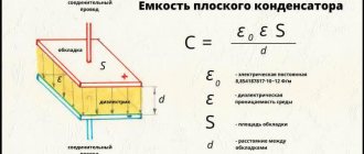
Dielectric losses in a dielectric can be characterized by power dissipation, which is determined by the formula
P = U2·ωC·tgδ,
where ω – angular frequency (ω = 2πf); C – dielectric capacitance; U is the voltage applied to the dielectric; tanδ – dielectric loss tangent.
Figure 4 shows an equivalent circuit and a vector diagram of a dielectric with losses. Dielectric loss angle
called the angle that complements up to 90° the phase shift angle φ between current and voltage in a capacitive circuit.
Rice. 4. Equivalent circuit a) and vector diagram b) of dielectric
with losses
Types of dielectric losses. Dielectric losses, according to their characteristics and physical nature, can be divided into four main types:
1) losses due to polarization;
2) losses due to through electrical conductivity;
3) ionization losses;
4) losses due to the heterogeneity of the structure.
Dielectric losses due to polarization
. Of all types of polarization with losses, dipole and ion-relaxation are the most common in dielectrics. They have common patterns:
a) tgδ at a certain frequency f1 has a maximum;
b) tgδ also has a maximum at a certain temperature t1, characteristic of a given dielectric.
In an equivalent circuit, these types of losses are well described by a chain of capacitance C and resistance r (Fig. 4,a).
Dielectric losses due to through conductivity
, in the equivalent circuit are well described by resistance R
(Fig. 4,a). They are independent of frequency:
P = U2/R.
Since resistance R depends on temperature, losses also depend on it. They increase with temperature according to an exponential law:
P = A exp(–b/T),
where A and b are material constants.
Tangent δ in this case can be calculated using the formula
tgδ = , (1)
where f – voltage frequency, Hz; ρ – resistivity, ;
Ionization dielectric losses
. These losses are characteristic of gaseous dielectrics. They appear if the voltage applied to the dielectric exceeds the critical value Ucr at which ionization processes begin. Up to the voltage Ucr, the dielectric losses are practically zero, and then they increase sharply, and they can be estimated using the approximate formula
where A is a constant coefficient, f is the field frequency.
Ionization losses also occur in liquid and solid dielectrics in gas bubbles and inclusions.
Dielectric losses due to structural inhomogeneity
.
They are observed in layered dielectrics: oil-impregnated paper, porous ceramics, textolite, fiberglass, etc. Due to the diversity of the structure of inhomogeneous dielectrics, there is no general formula for calculating dielectric losses.
Dielectric losses in gases
. Dielectric losses in gases at field strengths below the value required for the development of impact ionization of gas molecules are very small. In this case, the gas can practically be considered as an ideal dielectric. The source of dielectric losses of a gas can only be electrical conductivity, since the orientation of dipole gas molecules during their polarization due to the large distances between the molecules is not accompanied by dielectric losses.
But since gases have very low electrical conductivity, the dielectric loss angle is negligible. The value of tanδ can be determined by formula (1). For gas tgδ ≈ 4·10–8.
At field strengths greater than Ecr, ionization begins in the gas and losses increase sharply.
Dielectric losses in liquid dielectrics.
Among liquid dielectrics, nonpolar and polar ones should be considered separately.
In non-polar
In liquids, dielectric losses are due only to electrical conductivity. Pure liquid dielectrics have low electrical conductivity, and therefore dielectric losses are also low. You can calculate tanδ using formula (1). For example, for petroleum capacitor oil we obtain tgδ ≈ 0.001. Dielectric losses in non-polar dielectrics depend on temperature, since the resistivity of the liquid dielectric decreases with increasing temperature. For a non-polar dielectric, tgδ decreases with increasing frequency. And dielectric losses do not depend on frequency.
In the polar
losses in liquids are due to two reasons:
a) electrical conductivity; b) dipole polarization.
Losses caused by electrical conductivity depend only on temperature. For dipole polarization, tgδ has a maximum at a certain temperature t1. If we now take into account both types of losses and sum up both dependencies, we obtain the graph shown in Fig. 5, a. The influence of frequency f on tanδ and power dissipation is shown in Fig. 5b
Fig.5. The influence of temperature a) and frequency b) on losses in the polar
liquid dielectric
Dielectric losses in solid dielectrics.
In solid dielectrics all types of polarization and losses are possible. To clarify the general principles, solid dielectrics are divided into the following groups.
1. Dielectrics of molecular structure:
a) non-polar, b) polar.
2. Dielectrics of ionic structure:
a) tightly packed, b) loosely packed.
3. Ferroelectrics.
4. Dielectrics of inhomogeneous structure.
Non-polar
dielectrics have negligible dielectric losses, and they are used as high-frequency dielectrics. Tangent δ for them can be calculated using formula (1). Dielectric losses for non-polar dielectrics do not depend on frequency. As the temperature increases, the resistivity of the dielectric decreases, and this leads to an increase in the dielectric loss tangent.
Change in tgδ from temperature and frequency in polar
dielectrics
the same as for a liquid polar dielectric.
In solids with an ionic structure with dense packing of ions
only two types of polarization: electronic and ionic. In these dielectrics the dielectric losses are very small. At elevated temperatures in such substances, losses from through electrical conductivity increase. With increasing frequency, tgδ decreases, as in non-polar dielectrics, since the active current remains constant and the reactive current increases.
In solids with an ionic structure with loose packing of ions
There is a significant ion-relaxation polarization, therefore, patterns of change in tanδ with temperature and frequency characteristic of dipole polarization are observed.
There are two types of losses:
a) losses caused by the movement of weakly bound ions. They are considered as losses due to electrical conductivity, increasing with temperature and almost independent of frequency (tgδ decreases with increasing frequency);
b) losses caused by relaxation polarization, for which tanδ depends on temperature and frequency.
For most types of electroceramics, the number of ions participating in relaxation polarization continuously increases with temperature, therefore there is no maximum tgδ and the temperature dependence of tgδ, like non-polar dielectrics, has an exponential character to a first approximation.
Features of ferroelectrics
is that in them spontaneous (spontaneous) polarization manifests itself in a certain temperature range, up to the Curie point. Dielectric losses in ferroelectrics change little with temperature in the region of spontaneous polarization and drop sharply at temperatures above the Curie point, when the domain structure is destroyed.
Dependences of tanδ on temperature and frequency in dielectrics of inhomogeneous structure
very complex and are defined as the sum of the dependencies of the components.
LECTURE No. 6
Breakdown of dielectrics
General characteristics of the breakdown phenomenon
.
A dielectric, being in an electric field, loses the properties of an electrical insulating material if the field strength exceeds a certain critical value. This phenomenon is called dielectric breakdown
.
The voltage value at which breakdown of the dielectric occurs is called the breakdown voltage
Upr, and the corresponding value of the field strength is called
the dielectric strength
Epr.
The main types of breakdown are as follows:
– electrical breakdown;
– thermal breakdown;
– electrochemical breakdown (electrical aging).
Electrical breakdown
is caused by impact ionization by electrons, which occurs in a strong electric field and leads to a sharp increase in the electric current density.
Thermal breakdown
is caused by a progressively increasing release of heat in the dielectric under the influence of dielectric losses or electrical conductivity and leading to thermal destruction of the dielectric.
Electrochemical breakdown
is caused by slow changes in the chemical composition and structure of the dielectric, which develop under the influence of an electric field or partial discharges in the dielectric, leading to an irreversible decrease in insulation resistance and its breakdown at voltages significantly lower than the dielectric strength of the dielectric.
This process is also called electrical aging
of the dielectric.
Gas breakdown
. In gases, only electrical breakdown occurs. Due to radioactive and cosmic radiation, a small amount of charged particles is always present in the air gap. Electrons in an electric field are accelerated by the electric field and acquire additional energy:
W = g E λ,
where g is the charge of the electron, E is the field strength, λ is the average free path of the electron before the next collision.
If the voltage is sufficient (that is, E ≥ Epr), then a rapidly increasing flow of electrons occurs, leading to breakdown of the gap.
The breakdown voltage (Epr) of a gas depends on many factors. One of the most important factors is the type of field. In Fig.6. The dependences of breakdown voltage on the distance between the electrodes for three classical gaps are given.
The electrical strength of a gas also depends on the density of the gas, which is a function of pressure and temperature.
Rice. 6. Dependence of the electrical strength of gas on the shape of the electrodes and
distances between them: 1 – tip-plane; 2 – point-point;
3 – ball-ball
Breakdown of liquid dielectrics.
The theory of breakdown of liquid dielectrics is not as well developed as for gases. In liquid dielectrics, the breakdown mechanism and breakdown voltage depend on the purity of the dielectric.
There are three degrees of purity:
1) dielectrics contain emulsion water and solid mechanical impurities;
2) technically pure, dielectrics practically do not contain emulsion water and mechanical impurities;
3) especially thoroughly purified, i.e. they contain absolutely no water or mechanical impurities, and are also well degassed.
In especially carefully purified liquid dielectrics, only the electrical form of breakdown occurs. The density of a liquid is significantly greater than the density of a gas; therefore, the mean free path of electrons in them is significantly shorter (λ), and therefore the breakdown voltage is significantly higher.
In the electric power industry, technically pure liquid dielectrics are usually used, in which impurities are possible in small quantities. Emulsion water present in it, even in small quantities, especially greatly reduces the electrical strength of a liquid dielectric. The breakdown of moistened liquids occurs as follows. Droplets of emulsion water in an electric field are polarized, drawn into the space between the electrodes, deformed and, merging, form bridges with low electrical resistance, along which the discharge occurs. The formation of bridges leads to a significant decrease in oil strength.
Breakdown of solid dielectrics
. All types of breakdown are possible in solid dielectrics. Each of these types of breakdown can occur for the same dielectric, depending on the nature of the electric field (constant or alternating, pulsed, low or high frequency), as well as on the presence of impurities and defects in the dielectric.
Purely electrical breakdown
occurs when the influence of electrical conductivity and dielectric losses, which cause heating of the material, is excluded, and there is also no ionization of gas inclusions. Electrical breakdown occurs very quickly in a time of less than 10-7–10-8 seconds, and by its nature is a purely electronic process, i.e., impact ionization of atoms by electrons and the formation of avalanches occurs. In solid dielectrics, the mean free path of electrons is shorter than in liquid ones, therefore, to obtain the required ionization energy (W = g E λ ≥ΔW), the field strength must be increased.
Thermal breakdown
occurs when the amount of thermal energy released in the dielectric due to dielectric losses exceeds the amount of thermal energy that can be dissipated under given conditions. In this case, the thermal equilibrium is disturbed, and the process takes on an avalanche-like character and ends with charring, melting, burning, etc.
Electrochemical breakdown process
develops in electric fields with a intensity significantly lower than the dielectric strength.
One of the types of electrochemical breakdown is ionization
breakdown.
Some solid dielectrics and insulation systems have known porosity. Let’s say that gas (air) bubbles remain in the paper-oil insulation after adding oil. The distribution of tension between the oil insulation Em and air bubbles E is not uniform:
,
i.e., the tension applied to the air bubble is approximately 2.2 times greater than to the oil, and the strength of the air is much less
(Epr(voz) ≈ 30 kV/cm, Epr(m) ≈ 200 kV/cm). This leads to the fact that the air gap will break through several times at each half-wave of industrial frequency. With each breakdown, the paper chars and the oil decomposes with an increase in the air bubble.
This process is called partial discharge
. Partial discharges are present in many types of insulation, with each breakdown there is a slight decrease in the insulation strength, but over time, insulation damage accumulates and its strength decreases - insulation aging.
In the future, insulation breakdown may occur during switching overvoltages (during switching on or off electrical installations) or even at rated voltage.
It is almost impossible to produce layered insulation without partial discharges. Therefore, in layered insulation, a level of partial discharges is allowed that would ensure a sufficiently long service life (τ) of the insulation (dielectric lifetime) of up to 20 years.
LECTURE No. 7
Physicochemical and mechanical properties of dielectrics
The following properties are most important for dielectrics:
1. Humidity.
2. Thermal.
3. Mechanical.
Humidity properties. Many electrical insulating materials are used in conditions of high humidity, and water can get into them if the electrical equipment does not have a sealed housing, such as a capacitor.
Relative air humidity
is a ratio expressed as a percentage
| φ = 100, |
where m is the mass of water vapor per unit volume, g/m3; msat – mass of water vapor per unit volume at saturation, g/m3.
Relative humidity φ = 65% is taken as normal air humidity in our country. In air with normal humidity at 20 °C, the water vapor content is m = 11.25 g/cm3.
To protect the surface of electrical insulating parts from moisture, they are coated with varnishes that are not wetted by water.
The ability of dielectrics to be wetted by water is characterized by the contact angle θ of a drop of water applied to a flat surface of the body
(Fig. 7.) The smaller the angle θ, the stronger the wetting. For wetted surfaces, the angle is θ < 90°, for non-wetted surfaces – θ > 90°.
Rice. 7. A drop of liquid on the wetted surface of a dielectric (a)
and on a non-wetted surface (b)
If there is volumetric open porosity in the dielectric or if the structure is loose, moisture gets inside the dielectric. If a dry dielectric is placed in humid air, it begins to absorb moisture from the air. Moreover, the humidity of the material ψ will increase, asymptotically approaching the equilibrium humidity ψр corresponding to a given value of air humidity φ. Paper at relative air humidity φ = 65% has an equilibrium humidity ψр = 8%.
The most sensitive parameter of moisture in dielectrics is the dielectric loss tangent tgδ; it increases noticeably as the material is moistened, and the resistivity ρ also changes.
Moisture permeability
- this is the ability of materials to pass water vapor through themselves.
The amount of moisture m passing in time τ through the surface area S of a layer of insulating material of thickness h under the influence of the difference in water vapor pressure p 1
and p
2
on both sides of the layer is found by the following expression:
| m = П·(p1 – p2)·S·τ/h, |
where P is the moisture permeability of this material. In the SI system it is measured in seconds.
Thermal properties of dielectrics
. These include heat resistance, cold resistance, thermal conductivity and thermal expansion.
Heat resistance
- this is the ability of a dielectric to withstand exposure to elevated temperatures for a time comparable to the period of normal operation, without unacceptable deterioration of its properties. The insulation service life τ is related to the absolute temperature T by the following dependence (Fig. 8): lnτ = AT-1 + B, where A and B are constant values for a given material and given insulation aging conditions.
Rice. 8. Insulation life depending on temperature
GOST 8865–70 provides, in accordance with the recommendations of the International Electrotechnical Commission (IEC), for the division of electrical insulating materials into heat resistance classes (Y, A, E, B, F, H, C).
Cold resistance
is the ability of insulation to withstand low temperatures (for example, from –60 to –70 °C) without unacceptable deterioration of its properties. At low temperatures, as a rule, the electrical properties of insulating materials improve. However, many materials that are flexible and elastic under normal conditions become very brittle and rigid at low temperatures, which creates difficulties for the insulation to work.
Thermal conductivity
- this is one of the types of heat transfer from more heated parts to less heated ones, leading to equalization of the temperature of the material. The thermal conductivity of materials is characterized by the thermal conductivity coefficient γt, which is included in the Fourier equation:
| Pt = γt ΔS, |
where ΔРт is the power of the heat flow passing through the area ΔS, normal to the flow; – temperature gradient.
Thermal expansion
dielectrics are assessed by the temperature coefficient of linear expansion (), measured in K-1:
| Due to the large volume, this material is placed on several pages: 2 |
Get text
Types of dielectric losses
Depending on the electrical properties of various types of dielectrics, the following types of dielectric losses are distinguished, accompanied by heating of the dielectric:
- ionization losses observed in gases;
- relaxation losses in liquid (viscous) dielectrics as a result of relaxation polarization;
- scattering in substances with dipole polarization;
- polarization scattering in substances with through electrical conductivity;
- high frequency resonant losses;
- dielectric losses caused by the inhomogeneity of the structure of solid dielectrics.
Dielectric substances behave differently at different temperatures, with direct or alternating current. Maximum losses occur when a certain temperature threshold is reached. This threshold is individual for each substance. The tangent of the angle δ also depends on the applied voltage (Fig. 4).
Rice. 4. Dependence of tangent on voltage
Dielectric losses of solids
Solids have a special set of characteristics. For example, they differ in composition, structure and polarization, due to which dielectric losses occur. For dielectrics with reliability and good qualities, use:
- Seru.
- Paraffin.
- Polystyrene.
There are also dielectrics with through conductivity of electricity. These include:
- Quartz.
- Salt.
- Mica.
Ceramic and marble dielectrics, being crystalline, are typical examples of these values. They contain an admixture of semiconductors.
They have distinctive properties: dielectric losses will depend on environmental conditions. Values may change due to the influence of surrounding factors.
How to measure?
It is not very convenient to calculate dielectric losses using the formula. Manufacturers often determine the tg value empirically and indicate it on packaging or in reference books.
There are special measuring instruments, such as “IPI-10” (or the “Sh2” meter), which allow you to accurately determine the level of dissipation in dielectrics or find the tangent of the dispersion angle. The devices are quite compact and easy to use. With their help, you can study the properties of solids and liquid substances for dielectric losses.