May 6, 2016 Tips for an electrician kmelectric
Switching electrical circuits is one of the main elements of electrical engineering. This concept refers to switchings that are made in electrical connections, machines, cables, transformers, devices and devices that generate, consume and distribute electricity.
Switching devices, which can be purchased by following the link priborpostavka.ru/knopka-kme-4511, sequentially switch electrical circuits, close and open them.
Switching concept
Switching of electrical circuits refers to various switches made in all kinds of electrical connections, as well as in cables, wires, transformers, machines, various devices and devices that, in one way or another, generate, distribute and consume electricity.
As a rule, switching is accompanied by transient processes that arise as a result of the fact that currents and voltages are very quickly redistributed in the branches of electrical circuits.
The principle of operation of Router (router)
A router or router, router (from the English router), is a network device that, based on information about the network topology and certain rules, makes decisions about forwarding network layer packets (layer 3 of the OSI model) between different network segments.
Typically, a router uses the destination address specified in the data packets and determines from the routing table the path along which the data should be sent. If there is no described route in the routing table for an address, the packet is discarded.
Electrical circuit modes
The transition of a circuit from one mode to another is a transient dynamic process. While in a stationary steady state, the currents and voltages in DC circuits remain constant over time, with alternating current the time functions change periodically. The established modes for any parameters are completely dependent solely on the energy source. Therefore, every source of energy, direct or alternating, creates a corresponding current. Moreover, the frequency of the alternating current completely coincides with the frequency of the electrical energy source.
The occurrence of transient processes occurs when the modes in electrical circuits change in some way. This may include disconnecting or connecting circuits, changing loads, or the occurrence of various emergency situations. All these switchings are called commutation. From a physical point of view, all processes of transition of energy states correspond to the regime before and after switching.
Switching in DC machines
Switching in electrical machines is the process of switching winding sections from one parallel branch to another and related phenomena. During the switching process, the current in the switched section reverses direction. In Fig. Figure 6 shows the armature winding sections and the brush. The currents in the sections to the right and left of the brush have different directions. The section connected to the commutator plates, which are currently in contact with the brush (the brush short-circuits the section) is called switched. The time the brush short-circuits the switched section is called the switching period TC.
Fig.6. Switching in a DC machine.
The section switching process proceeds quite quickly: the switching time of one section (switching period Tk) is approximately 0.001 - 0.0003 s. The phenomena that occur during switching significantly affect the reliability and durability of a DC machine.
If commutation is poor, significant sparking occurs under the brushes and associated commutator burning occurs.
The commutation period depends on the width of the brush bshch and the peripheral speed of the commutator vk
TK = bsh/ vk
Fig.7 Scheme for calculating the current of the switched section
The nature of the switching process depends on the law of change in the current of the switched section iKS during the switching period. To determine the current of the switched section, we make the following assumptions:
-transition resistance between the brush and the plate depends only on the area of contact of the plate with the brush, for plate 2 in Fig. 7 it is Sн1= bш1lШ, for plate 3 in Fig. 7 it is Sш2= bш2lШ, where lШ is the length of the brush, bш1+ bш2= bш ;
- the width of the brush bsh is equal to the width of the commutator plate;
- active resistances of the section and collector plates can be neglected.
In Fig. 7 shows a diagram of a simple loop winding. For simple wave windings, the switching process is similar; the brush also overlaps the adjacent collector plates to which the wave winding sections are connected. For complex windings, the brushes are made wider so that they simultaneously cover sections of all parallel branches of the complex winding, but the switching process, in this case, differs little from switching in a loop winding.
The switching process for a given direction of armature rotation (Fig. 7 section switching 1
will begin from the moment when the collector plate
3
comes into contact with the right edge of the brush, which is called the advancing edge.
From this moment, section 1 will be short-circuited by the brush and the current iKS will change in it (from + ia to -
ia
).
With further movement of the armature through the switching period Tk,
the collector plate 2
will come At this moment, the commutation of section 1 will end, the section will move to another parallel branch of the winding and the current in it will change direction to the opposite direction compared to its direction before commutation began.
To determine the law of current change in the switched section 1
at time
t
(0 < t<
Tk),
according to Fig. 7 can be written
i1= ia+ iKS; i2= ia- iKS; i1+ i2=2 ia
and for the circuit of the switched section
i1rш2 — i2rш1 =±∑e
where, rsch1 and rsch2 are the contact resistances between the brush and plates 2 and 3, respectively; ±∑e is the total EMF of the switched section, the sign ± means that the direction of the EMF can be any.
Substituting the previous ones into the last expression, we get
ia(rsch2 - rsch1) + iKS(rsch1+ rsch2) =±∑e
from where: iKS = ia ±
since contact resistances are proportional to the overlap areas of the brush and plate, we can write
rsch1=k Shch1=k vk t
rsch2=k Sch2=k vk(Tk – t)
let's introduce the relations = =
dividing the numerator and denominator in the expression for iKS by rш2 and bringing similar ones, we get
iKS = ia ±
It is clear from the equation that the nature of the change in current iKS during the switching period depends on the value of the total EMF and its sign. Depending on this, three types of switching are distinguished.
Straightforward
switching in DC machines takes place at, The graph of changes in iKS is shown in Fig. 8. The current iKS changes according to a linear law, only as a result of a change in the contact resistance of the brush with the collector plates rsch1 and rsch2.
Fig.8. Straight-line switching
In a real machine it is always different from zero. The sum of the EMF of the switched section can be decomposed into two components
where, e-reactive EMF of the section or EMF corresponding to the inductive reactance of the section (any section of the armature winding of a DC machine always has inductive reactance); eur - rotational emf or emf induced in the section by external magnetic fields. The rotational emf, when positive, increases the reactive emf, and when negative, it decreases. In the latter case, when the reactive EMF and rotational EMF are equal, the reactive EMF of the section is completely compensated, and only then does the commutation become linear.
Denoting ia =ipr and id, where ipr is the current of the switched section during straight-line commutation, id is the additional current of the switched section, iKS can be represented in the form
iKS= ipr ±iD
Slow motion
commutation occurs in the case when the reactive emf
e
has a greater value than the rotational emf compensating for it or in the absence of eur. The graph of changes in iKS during slow commutation is shown in Fig. 9.
Fig.9 Delayed commutation
Slow commutation usually occurs in machines without reactive emf compensation. The additional current tends to delay the change in current in the switched section, and. the current in the section changes more slowly. During slow commutation, the additional current is closed across the brush, and in the sliding contact under the running part it has the same direction as the current ia under the running part - counter to this current. Consequently, the current density under the running edge of the brush will be greater than under the advancing edge.
Slow commutation is characterized by sparking of the running edge of the brush. Such sparking occurs when, upon completion of section switching at time t = Tk, the current iD does not have time to reach zero and occurs when the section is opened! its rupture (Fig. 10). This current is called the breaking current itimes. The higher the breaking current, the stronger the sparking under the running edge of the brush
Fig. 10 Occurrence of interruption current
Accelerated commutation occurs when the reactive EMF is overcompensated, when the additional current is opposite in sign to the straight-line commutation current and exceeds it in magnitude (Fig. 11), which is observed in DC machines with strong compensation of the reactive EMF. With accelerated commutation, an additional current iD appears, which is oppositely directed compared to the slow commutation current. Consequently, the current of the switched section will change faster than with straight-line commutation, and the current density under the advancing part of the brush will be greater than under the running part.
Fig. 11 Accelerated switching
With a strong acceleration of commutation, it is also possible for a breaking current to appear (Fig. 12) and sparking under the brushes.
Fig. 11 Switched section current at high 1 and low commutation acceleration
Switching is considered optimal if it is accelerated by 15% compared to straight-line switching.
Clicking the relay correctly: switching powerful loads
Controlling powerful loads is a fairly popular topic among people who are in one way or another concerned with home automation, and in general, regardless of the platform: be it Arduino, Rapsberry Pi, Unwired One or another platform, turn it on and off some kind of heater, boiler or a duct fan will have to be used sooner or later.
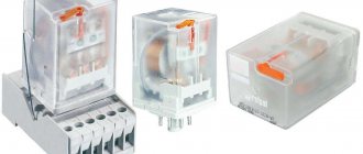
The traditional dilemma here is what to actually commute with. As many have learned from their sad experience, Chinese relays do not have the proper reliability - when switching a powerful inductive load, the contacts spark strongly, and at one point they may simply stick. You have to install two relays - the second one to protect against opening.
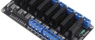
Instead of a relay, you can install a triac or solid-state relay (essentially the same thyristor or field-effect device with a logical signal control circuit and an opto-isolator in one package), but they have another disadvantage - they heat up. Accordingly, a radiator is needed, which increases the dimensions of the structure.
I want to tell you about a simple and quite obvious, but at the same time rarely seen scheme that can do this:
- Galvanic isolation of input and load
- Switching of inductive loads without current and voltage surges
- No significant heat generation even at maximum power
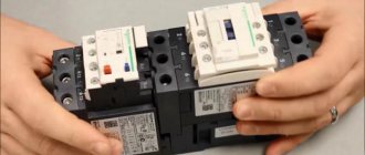
But first, a few illustrations. In all cases, TTI relays of the TRJ and TRIL series were used, and a 650 W vacuum cleaner was used as the load.
Classic scheme - we connect the vacuum cleaner through a regular relay. Then we connect an oscilloscope to the vacuum cleaner (Caution! Either the oscilloscope or the vacuum cleaner - or better yet, both - must be galvanically isolated from the ground! Don’t put your fingers or eggs in the salt shaker! They don’t joke with 220 V!) and take a look.
I had to reach almost the maximum mains voltage (trying to tie an electromagnetic relay to the zero crossing is a disastrous task: it is too slow). A short surge with almost vertical fronts boomed in both directions, and interference flew in all directions. Expected.
A sudden loss of voltage on an inductive load does not bode well - the surge will fly upward. In addition, do you see this noise on the sine wave milliseconds before the actual shutdown? This is the sparking of the relay contacts that have begun to open, which is why they will one day become stuck.
So, it is bad to switch an inductive load with a “naked” relay. What will we do? Let's try to add a snubber - an RC chain of a 120 Ohm resistor and a 0.15 µF capacitor.
Better, but not much. The ejection decreased in height, but was generally preserved.
Same picture. The debris remained, moreover, the sparking of the relay contacts remained, although greatly reduced.
Conclusion: with a snubber it is better than without a snubber, but it does not solve the problem globally. However, if you want to switch inductive loads with a regular relay, install a snubber. The ratings must be selected for a specific load, but a 1-W resistor at 100-120 Ohms and a capacitor at 0.1 µF seem to be a reasonable option for this case.
Related literature: Agilent - Application Note 1399, “Maximizing the Life Span of Your Relays.” When operating the relay on the worst type of load - a motor, which, in addition to inductance, also has a very low resistance at start - good authors recommend reducing the rating life of the relay by five times
.
Now let’s make a knight’s move - we will combine a triac, a triac driver with zero detection and a relay into one circuit.
What's in this diagram? On the left is the entrance. When “1” is applied to it, capacitor C2 is almost instantly charged through R1 and the lower half of D1; Optorelay VO1 turns on, waits for the next zero crossing (MOC3063 - with a built-in zero detector circuit) and turns on triac D4. The load starts.
Capacitor C1 is charged through a chain of R1 and R2, which takes approximately t=RC
100 ms. These are several periods of mains voltage, that is, during this time the triac will have time to turn on, guaranteed. Next, Q1 opens and relay K1 turns on (as well as LED D2, shining with a pleasant emerald light). The relay contacts bypass the triac, so then - until it turns off - it does not take part in the operation. And it doesn't heat up.
Switching off is in reverse order. As soon as “0” appears at the input, C1 is quickly discharged through the upper arm of D1 and R1, the relay turns off. But the triac remains on for about 100 ms, since C2 is discharged through the 100-kilo-ohm R3. Moreover, since the triac is held open by current, even after VO1 is turned off, it will remain open until the load current drops in the next half-cycle below the holding current of the triac.
Beautiful, isn't it? Moreover, when using modern triacs that are resistant to rapid changes in current and voltage (all major manufacturers have such models - NXP, ST, Onsemi, etc., names begin with “BTA”), a snubber is not needed at all, in any form.
Moreover, if you remember the smart people from Agilent and look at how the current consumed by the motor changes, you get this picture:
The starting current exceeds the operating current by more than four times. During the first five periods - the time by which the triac is ahead of the relay in our circuit - the current drops by approximately half, which also significantly softens the requirements for the relay and prolongs its life.
Yes, the circuit is more complex and more expensive than a regular relay or a regular triac. But often it's worth it.
Methods for transmitting packets in networks
Datagram method
Datagram method - transmission is carried out as a set of independent packets. Each packet moves through the network along its own route and the user receives the packets in random order.
- Easy transfer process
- Low reliability due to the possibility of packet loss and the need for software to assemble packets and restore messages
Logical channel
A logical channel is the transmission of a sequence of packets linked in a chain, accompanied by the establishment of a preliminary connection and confirmation of the receipt of each packet. If the i-th packet is not received, then all subsequent packets will not be received
Virtual channel
A virtual channel is a logical channel with the transmission of a sequence of packets connected in a chain along a fixed route.
- The natural sequence of data is preserved; sustainable traffic routes; resource reservation possible
- Hardware complexity
Automatic release methods
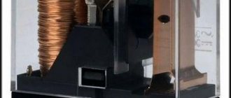
Protective switching devices have relays in their design. They are part of the releases. Relays can be electromechanical or statistical. The specified parameters of semiconductor materials are monitored and compared. This principle is inherent in introductory machines.
Read also: OKFS code, how to find out by tax identification number
Electromechanical varieties can be made on the basis of electrothermal, electromagnetic or combined elements. The input switching device of the presented type is installed in apartments, houses, industrial facilities, etc.
Releases may not have a set time interval when tripping occurs. Also on sale are devices with independent time delay or operation with an inverse dependence on current.
Calculation of lumens per square meter for different rooms
Types of switches
Switching devices, which belong to the type of switches, in turn, are divided into subgroups. There is a disconnector, a switch and a short circuit. In the first case, the device interrupts the supply of electricity to a circuit that has insignificant current. This type of device is used to inspect or repair the system. The disconnector has a distance between contacts for insulation.
Switches transfer electrical current from one circuit to another. The short circuiter is not produced and is not used in modern equipment. It creates a short circuit.
There are devices on sale that combine the functions presented. For example, this could be a disconnect switch. This is a switch with a chamber for extinguishing the arc. It can work in both one and two directions. If such a switch does not have a chamber for extinguishing the arc, this device belongs to the group of disconnectors.
How is the second law of commutation formulated?
According to the second law of commutation
the voltage on the capacitor cannot change abruptly (that is, it (the voltage) changes smoothly with any changes in the circuit (although there are incorrect
switchings
in which this is not noticeable)). ...
Interesting materials:
How to create a new layer in Illustrator? How to create an ISO disk image in alcohol? How to create a clipping mask in InDesign? How to create a clipping mask? How to create a public page in Viber? How to create a folder in Thunderbird? How to create a lookalike audience? How to create a sudo user? How to create a private channel in Telegram? How to create a private channel in Telegram?
4.1. Switching system structure
A switching system is
a set of equipment designed to receive and distribute incoming information along communication lines.
Table 4.1 – Classification of switching systems
| Classification feature | Switching system |
| Type of switching and control equipment | · decade-step · coordinate · quasi-electronic · electronic |
| Signal presentation form | · analog · digital |
| Type of information transmitted | · telephone · telegraph · data transmission · broadcasting |
| Space occupied in a telecommunications network | · central · nodal · terminal · transit · incoming message nodes (IMS) Outgoing message nodes (UIS) |
| Territorial division | · intercity · urban · rural · institutional |
| Capacity | · small capacity medium capacity · large capacity |
| Channel Separation | · with spatial division · with time division |
| Switching method | · channel switching packet switching · message switching |
To perform its functions, the switching system must include the following types of equipment (Figure 4.1):
1) Subscriber line blocks
(BAL) connect subscriber lines (AL) to the system.
2) Trunk blocks
(BSL), to which trunk lines (CL) are connected through CCL (trunk line sets) for communication with other switching systems.
3) Commutation field
(KP) switches incoming lines with outgoing lines. The switching field can be built on the basis of spatial separation of channels and then multiple coordinate connectors (MCC), reed relays, and ferrids are used as switching elements. The time division switching field is based on the use of pulse code modulation (PCM) and uses semiconductor storage devices and logic integrated circuits as elements.
4) Control system
(SU) – performs all logical functions for managing connection establishment processes.
5) Generating equipment
– generates acoustic signals.
Figure 4.1 – Generalized structure of the switching system
Controlled electric drive
Constant voltage is widely used to provide efficient speed control of electric motors. Every year, controlled electric drives are increasingly penetrating into those areas in which the use of a conventional uncontrolled drive was previously considered sufficient. Experts are confident that the combination of an inverter plus an asynchronous (or valve) electric motor in the near future will increasingly crowd out traditional types of drives. And for such an inverter drive, DC power supply is natural and most efficient.
Drive and releases
The drive of the switching device is driven manually or contactlessly. There are systems with a combined control system. Switching off is done using springs. They are set in motion after the release is released. This detail eliminates the possibility of keeping the contacts in the on position in the event of an emergency.
The release is a system of ligamentous articulated levers. They connect the actuator with movable contacts, which, in turn, are adjacent to the tripping spring.
It is the releases that are responsible for maintaining the required parameters of the circuit they protect. If the system exhibits deviations from the normal value, these elements turn off the power.
Switches
Switching is rightfully considered one of the most popular modern technologies. Switches all over the front are crowding out bridges and routers, leaving the latter only to organize communications through the global network. The popularity of switches is primarily due to the fact that they allow increasing network performance through segmentation. In addition to dividing the network into small segments, switches make it possible to create logical networks and easily regroup devices in them. In other words, switches allow you to create virtual networks.
In 1994, IDC gave its definition of a local network switch: a switch is a device designed in the form of a network hub and acting as a high-speed multiport bridge; The built-in switching mechanism allows you to segment the local network, as well as allocate bandwidth to end stations in the network.
Switches first appeared in the late 1980s. The first switches were used to redistribute bandwidth and, accordingly, increase network performance. We can say that switches were originally used exclusively for network segmentation. Nowadays, there has been a reorientation, and now in most cases switches are used to connect directly to end stations.
The widespread use of switches has significantly improved network efficiency by distributing bandwidth evenly among users and applications. Although the initial cost was quite high, they were nevertheless much cheaper and easier to set up and use than routers. The widespread use of switches at the workgroup level can be explained by the fact that switches can increase the efficiency of an existing network. At the same time, to improve the performance of the entire network, there is no need to change the existing cabling system and end-user equipment.
General term switching
used for four different technologies:
- configuration switching,
- frame switching,
- cell switching,
- conversion between frames and cells.
Configuration switching is based on finding a match between a specific switch port and a specific network segment. This mapping can be programmatically adjusted as users connect or move around the network.
When switching frames, frames from Ethernet networks, Token Ring, etc. are used. When a frame enters the network, it is processed by the first switch on its path. The term processing refers to the entire set of actions performed by the switch to determine its output port to which it is necessary to send a given frame. After processing, it is transmitted further through the network to the next switch or directly to the recipient.
ATM technology also uses switching, but its switching units are called cells. Conversion between frames and cells allows stations on an Ethernet, Token Ring, etc. network to communicate directly with ATM devices. This technology is used to emulate a local network.
Switches are divided into four categories:
- Simple stand-alone workgroup network switches allow some network devices or segments to exchange information at the maximum speed for a given cabling system. They can act as bridges to communicate with other network segments, but do not translate protocols or provide increased throughput with individual dedicated devices such as servers.
- Workgroup switches of the second category provide high-speed communication of one or more ports with a server or base station.
- Enterprise departmental network switches, which are often used to interconnect workgroup networks. They provide greater administration capabilities and improve network performance. Such devices support a tree-like communications architecture, which is used to transmit information over backup channels and filter packets. Physically, such switches support redundant power supplies and allow you to quickly change modules.
- Enterprise network switches that dispatch traffic to determine the most efficient route. They can support a large number of logical network connections. Many enterprise switch manufacturers offer ATM modules as part of their products. These switches translate Ethernet protocols into ATM protocols.
general characteristics
The purpose of switching devices is reduced to the process of passing electricity through closing and opening the circuit. Today, all existing units of this type can be divided into two categories. The first group includes contact (mechanical) devices, and the second group includes non-contact (semiconductor or gas-discharge) varieties.
The most common switching type devices are switches, knife switches, contactors, relays, and fuses. They have certain features that must be taken into account when choosing. It is necessary to purchase a switching device in accordance with the operating conditions.
The presented units may have several poles in their design. Their number can be from one to four. In accordance with this indicator, devices are also divided into groups. Most often, bipolar products are on sale. They have two positions - “off” or “on”.