About grounding
Before you do anything with electricity, you need to make sure there is a good grounding in your home.
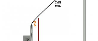
You won’t be able to simply take and connect a regular household gasoline/diesel/gas generator to the electrical network at home. Precautions must be taken. The first is that your generator must be well grounded. Then you have a good chance of not getting an electric shock when the static from your favorite sweater penetrates the insulation of the generator winding. In general, you should not touch a running generator unnecessarily. It is worth remembering that the network is not always 220V. Switching on lines, lightning discharges in the distance, and static discharges produce such interference that short pulses of several kilovolts are not uncommon in the network. They combat this by installing arresters and surge protection devices at the entrance to the house, but this is a very rare practice in the Russian Federation. So let the spark go into the ground, and not through you - make good grounding throughout the house. Without this, you simply cannot do anything further!
How does the automation system for a generator work?
If the main network is lost, the autostart system panel controller attempts to start the generator and, if successful, after warming up the generator, switches the load from the main network to the backup one. If the startup attempt fails, the controller makes repeated startup attempts. When the main network appears, the controller, after a fixed waiting time, switches the load to the main network, and after cooling the generator, turns it off. The system operation algorithm is presented in Fig. 1.
Figure 1. How the generator autostart system works
About generators
By the way, many household gasoline generators have windings that are not connected to ground in any way.
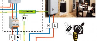
And this is quite normal when you are powering one power tool from a generator. But when you need to connect the generator to the house, you need to make a neutral wire (N) and a phase wire (L). To do this, one of the terminals of the generator is grounded and from this grounding point two wires must be independently led into the house - one will be the neutral N, and the second will be the protective ground (PE). When choosing a generator, you need to pay attention to whether its output can be grounded; sometimes this is prohibited in the instructions for the generator, then such a generator will not suit you. Often on the Internet you can see diagrams for connecting a generator without grounding and separating the N and PE lines. Don't do this, you'll live longer. Such schemes work well until the first unfortunate set of circumstances. Typical power supplies for modern electronic devices contain capacitors from lines L, N to ground. If N is not grounded at the generator, then due to these capacitors on line N there will be, if you're lucky, 110 volts relative to ground. By the way, many gas boilers stop working altogether in this mode. I already wrote above about the influence of statics without the presence of grounding.
Principle of operation
High-quality automatic transfer of a reserve for a generator is expensive, so many home craftsmen decide to make this device with their own hands, using the same parts as in standard factory units. The main and most expensive part is the multifunction controller.
To ensure the power part of the master, contactors are used, which are used to guarantee switching from the main line to the local network. In order to compactly place all the parts, you need to prepare a fairly spacious cabinet or panel, which will best suit the size of the unit being manufactured.
What kind of lighting do you prefer?
Built-in Chandelier
The traditional ATS circuit is always equipped with an automated control mechanism that operates using normal DC voltage. The high-quality implementation of this idea is entrusted to the power supply. Most often, specialists use a standard high-power battery, since under increased loads a low-power unit quickly discharges.
When choosing a controller, you need to check the presence of an inverse air damper. This unit is especially useful in situations where the consumer is using a generator with a mechanical damper.
When buying durable contactors, you need to focus on throughput indicators. When the equipment does not have electromechanical protection, it must be purchased separately.
When all the elements are in stock, you can safely begin manufacturing the AVR. You need to start by installing all the elements and components in the internal compartment of the electrical panel. This process must occur in such a way that no intersections are formed between the conductors, and all contacts and terminals are easily accessible. Next, the power section and controllers are connected.
During the connection process, the presence of two powerful cables that are included in the automatic backup panel must be taken into account. One of them must be designed for the main network, and the second - for the backup power line. Their alternate use is due to different operating algorithms of the equipment. But at the output, only one power cable is pulled to the consumer.
The abbreviation AVR is an abbreviation for automatic reserve entry. Sometimes it is deciphered as “automatic transfer switch”, which, however, does not affect the functions that this device performs. It works on the principle of an electric relay: it automatically switches the consumer from the main network to a backup source of electricity if the voltage in the first one disappears.
Installing an ATS on a generator
involves several stages:
- We determine which connection scheme will be used.
- We select the equipment on the basis of which the ATS connection diagram
, according to the customer’s requirements. - We install automatic transfer of reserve and connect it to the main power source.
- We install the generator and connect control systems to it.
- We carry out commissioning work and put the ATS system into operation.
Before connecting the ATS to the generator
, you should decide on the installation location of the device and the electric generator. The choice of location is important, since it is not advisable to expose the ATS unit to sudden temperature changes. Therefore, installing it in cold rooms and outdoors is not advisable.
The electric generator itself must be installed in places where exhaust gases can be removed. In cold weather, it is better to install it in warm rooms to ensure quick start-up and the engine reaching operating temperature. This is especially important for diesel devices, the power plant of which is more susceptible to the effects of cold. In one of our previous articles, we talked about how to start a diesel generator in severe frost .
Make sure that the battery is charged and there is fuel in the tank.
Expert opinion
It-Technology, Electrical power and electronics specialist
Ask questions to the “Specialist for modernization of energy generation systems”
Do-it-yourself automation for a generator 7 Remote automatic starting of the generator from a key fob You can add a radio module to the system and you can start the generator remotely, via a radio channel. Ask, I'm in touch!
About AVR schemes
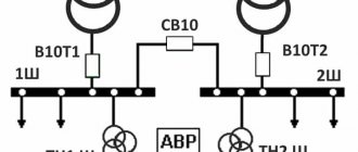
There are several different schemes for implementing ATS. Next I will write about the safest, from my point of view, single-phase ATS circuit. I do not advise economically making an ATS on one contactor or with switching only one phase wire. Only together with neutral.
In the diagram shown, power from the network and from the generator is supplied through inputs 1 and 2. They are protected by paired circuit breakers. The switching and indication circuits are powered through additional circuit breakers. It can be seen that the relay coils are electrically interlocked. For the sake of simplicity, a microcontroller not shown in the diagram, which closes the circuits at the switching point TK1 or TK2, is responsible for turning on one or another input.
The fundamental point is the presence in the ATS of 2 interlocking circuits - mutual mechanical interlocking of the contactor switching inputs and mutual electrical interlocking of the contactors. In order to save money, home-made people sometimes neglect these blockings in their designs, but in vain. A circuit without interlocks can work for some time, but at some point the contacts will burn, the return springs will weaken and a short circuit will occur between the inputs. Firstly, it threatens a big bang if both lines are energized, but this is not the biggest problem. It is much more important that your generator, unexpectedly for the electricians repairing the wiring, can release voltage into the general network - in an unfavorable combination of circumstances, the electricians repairing the line may die. For you this is already a criminal article.
How to assemble an AVR with your own hands.
If you are familiar with the basics of electrical engineering, you can try to make an ATS yourself, based on the diagram. But it is better, of course, to entrust this to a specialist with experience in assembling electrical panels.
To assemble the AVR unit with our own hands, we will need:
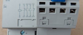
- Three-pole starters with blocks of additional contacts (1NO and 1NC) – 2 pcs. The power is selected based on the input circuit breaker installed in your panel.
- Automatic switches: Three-pole, current corresponding to contactors - 2 pcs (QF1, QF2) and 1 pc. to protect the voltage control relay - 3p S6A (QF3). Single-pole – B6A – 1 piece (QF4).
- Voltage monitoring relay CM-PVE or equivalent (KV).
- Modular contactor with 220V coil and three contacts (2NO and 1NC) (KL1). How to assemble an AVR with your own hands.
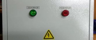
- Signal lamps for 220V, one red and one green (HL1, HL2).
- A metal cabinet with a mounting plate and dimensions corresponding to the equipment being installed (everything should not be end-to-end, and there should not be too much free space).
- DIN rail – approximately 0.5 m.
- DIN rail terminals - if desired, you can do without them by connecting cables directly to breakers and contactors.
Below is an approximate location of the equipment in the shield. Then everything is simple, first we wire the power lines using the mounting wire PV3 or PuGV (the cross-section is not lower than the cable coming from the network), and then the control circuits with the same wire are only 1mm2. PuGV and PV3 are necessarily pressed into NShVI tips.
Approximate location of the equipment in the panel.
Expert opinion
It-Technology, Electrical power and electronics specialist
Ask questions to the “Specialist for modernization of energy generation systems”
Services for connecting and setting up ATS If the total power of consumers available in the house exceeds the capabilities of the generator or the unit itself is not powerful enough, only those devices and equipment that are really necessary to ensure the normal functioning of the facility are connected to its line until the main one is turned on power supply Ask, I'm in touch!
About contactors
Thus, the use of conventional relays is out of the question for us; only specialized contactors are suitable.
For higher powers there is also an option with motorized drives, but this is expensive and redundant for typical home use. To make a mechanical interlock, you need to select contactors that can work in pairs. Typically, mutual interlocking is achieved by installing identical contactors next to each other and installing an additional option - a mechanical interlock. It is sold separately from contactors and costs pennies.
Mutual electrical interlocking is possible if the contactor has additional signal contacts that operate to open. Sometimes they are immediately built into the contactor, sometimes they can be purchased and installed as an option.
Leading contactor manufacturers have such equipment in their lines. So finding and buying a kit is not difficult. True, prices for branded contactors are an order of magnitude higher than ours/Chinese ones. Since the number of switching cycles is not expected to be large, the choice of Chinese contactors is quite justified. The only disadvantage is that the contactor coils hum quite loudly during operation.
More about the switching power. The contactor contacts must be able to handle the maximum amount of power you are allowed to draw in your home. For me it is 10 kW, so I chose contactors for a permissible current through one contact of approximately 50 amperes. It is worth noting that for some reason the switched power for a typical three-phase contactor is indicated in the passport as the total for all three phases, so you need to carefully look at what the permissible current is through exactly one contact.
How to automate generator startup?
The generator start automation system only works with generators equipped with an electric starter. If your generator does not have an electric starter, then you can check with the generator manufacturer whether it is possible to purchase and install an electric starter.
Fig 2. Honda generator electric starter.
When starting, the engine is spun by a commutator electric motor, which is shown in Figure 2. The commutator electric motor is powered by direct current from the battery (after starting, the battery is recharged from the generator driven by the main engine). But the electric starter has a significant drawback: in order to crank the crankshaft of a cold engine, especially in winter, it needs a large starting current, which is supplied by the battery, which rapidly loses maximum current and capacity as the temperature drops. Sometimes, together with the use of too viscous oil, this makes starting in cold weather impossible. Despite the presence of these disadvantages, using an electric starter is the most convenient way to start the engine of both gasoline and diesel, as well as gas generators.
To avoid problems starting the generator in winter, it is better to keep the generator in a warm room (or in a special box for the generator). But statistics show that on average 40% of our customers leave their generator outside. In such cases, we recommend changing the spark plugs in winter and using all-season semi-synthetic oil.
About the control scheme
When I was creating an AVR, I had several special requirements for its operation:
- My electricity doesn’t go out that often, so I decided that I didn’t need the autostart of the generator, but I decided not to give up the automatic stop of the generator: when the network is restored, the generator itself goes quiet and it’s immediately clear that now everything is fine with the power supply, and gasoline is saved
- After starting the generator, you need to give it time to warm up and only after warming up give it a load. Those. I needed a timer to turn on the ATS after applying voltage from the generator
- After the network voltage was restored, repeated outages often occurred after a short period of time, so I needed a timer that would wait a while before switching from the generator to the network and would not immediately turn off the generator
- They say it is useful for the generator to run a little without load before turning it off. And for this I also needed a timer
Thus, the picture emerged that I needed a controller with several timers.
At that time, I was interested in coding on AVR, so I decided to make such a controller on Atmega 8a. It would be nice if the controller worked for a long time and reliably. Besides, I couldn’t think of anything else to make a complete galvanic isolation and equip the controller with a watchdog timer. Well, make the diagram and program as simple as possible. Since I was doing everything for myself, I decided to leave all the settings and calibrations in the code - the entire UI was reduced to one LED)
The main task of the controller is to monitor the voltage at the inputs and, if necessary, switch the inputs. In this case, input from the village network has priority.
It is worth noting here that the quality of the network is such that fluctuations from 150 V to 250 V are quite common. Therefore, the concept of good mains power is very vague. After some time, I solved this problem when I installed one powerful 11 kW thyristor voltage stabilizer for the whole house. But, it’s important, the stabilizer can only be installed before the AVR, and not after! It is strictly not recommended to turn on the stabilizer for the generator. There is a danger that under a certain combination of loads, especially any powerful pumps, the system of a generator and stabilizer will become unstable and enter into self-oscillations.
After some thought, I drew such a diagram in Eagle.
The circuit has two identical transformer power supplies; if there is voltage at any of the inputs, the circuit is provided with power. A voltage of 600V is possible between the inputs, so the insulation of the transformers must be good. Power is taken after the QF3 and QF4 packets, respectively.
Each source has a resistive voltage divider, protected from overvoltage by a zener diode - from it, the network voltage is measured using a microcontroller ADC using simple calculations.
To switch the contactor coils, a standard circuit from the datasheet is used to control semistores. 2 pieces ). Coils are an inductive load, so snubber circuits at the resistor and capacitor output are required.
I had a relay module with Ali that is used to stop the generator. In the diagram it is just a rectangle with three pins.
Among the features, the TL431 is also used as a reference voltage generator. Otherwise, everything is included as standard for Atmega 8. There are LEDs to indicate the presence of supply voltage at the inputs and one device status LED. The circuit is clocked using an external quartz at 16 MHz.
Eagle gave me this printed circuit board. No SMD, triacs and stabilizer with light radiators.
Two toroidal transformers are installed directly on the board. The board was made using the traditional amateur radio method using photoresist. After installation, I covered it with three layers of acrylic varnish. I hope the high voltage doesn't break through.
ATS with generator autostart
How will the generator start if the power from both inputs disappears? Contact No. 12 is used to connect an external +12V power supply to the ATS.
When you lose voltage on two inputs, all contacts K1, K2, K3 are in an open state. In this case, the internal contact of relay K4 automatically closes. Due to this, a start signal for the generator is generated.
Most generators with ATS capability control the damper with their own automation. To do this, they only need a start signal. You just serve it.
If you don’t have this, then you can make such a system yourself.
After the pulse is given, the diesel generator set starts and warms up. When it warms up, the voltage on relay KV1 reaches normal. KV1 is something like a three-phase motor protection relay.
It is necessary to control the voltage of a 3-phase network (correct phase rotation and their nominal value). For example, this would be suitable - CKF-317.
After operation, relay KV1 closes its contact KV1.1 and the voltage reaches connector No. 16. U also goes to pin No. 9 (it controls the internal circuits of the AVR) and No. 22.
AVR sees this and sends a signal to close relay K3 and coil KM3. After which the power contacts of the KM3.1 generator starter are turned on. The entire load is powered from the generator.
Technical characteristics of the AVR shield
| Specifications | Meaning |
| Rated voltage, V | 220; 380 |
| frequency Hz | 50 |
| Rated current, A | 16; 25; 40; 63; 100; 160; 250; 400; 630 |
| Type of climate control panel | UHL 3.1 according to GOST 15150-69 |
| Switching time, s no more | 0.2 |
| Controlled parameters | Loss of at least one of the phases; symmetrical or asymmetrical reduction in voltage of one of the phases; change of phase sequence |