Greetings, friends!
Have you heard this word - datasheet? In recent years, our vocabulary has been considerably enriched with Anglicisms.
People who work in electronics and tinker with computers are probably familiar with this term. For those who are just getting ready to plunge into this exciting business, read on!
Datasheet is transliterated data sheets, reference sheets with information. It is an official document of the manufacturer of electronic components.
It contains a technical description of the component, its parameters, operating modes, switching diagrams and other information.
Features of reading circuits
In circuit diagrams, conductors (or tracks) are indicated by lines.
This designates conductors that intersect, but they do not have a common connection and are not electrically connected to each other.
And this is what they look like if there is a connection between them. The black dot is a node in the circuit. A node is a connection of several conductors or parts together. They are electrically connected to each other.
Common point
Beginner radio amateurs often have a question: what is this symbol on the diagram?
This is the common point (GND, ground). Previously, it was called the common wire. This is how a single power wire is designated. Usually this is a minus of nutrition. Previously, in the diagrams they could make the common wire and the power plus. In this case, the diagram without a common point would look like this:
A common point with unipolar power supply looks visually better and more compact than if you simply make a single line between them.
It is also called a common point because any other points on the diagrams can be measured relative to it. For example, place the multimeter probe on a common point, and with the second probe you can check any part of the circuit in the diagram.
Why can it be called ground (GND)? Previously, the chassis of the device body could be used as a common wire. This has caused confusion between grounding and earth. It is interpreted in the context of the schema. The circuit that was discussed above - the common point (ground) is simply a minus of the power supply. Another thing is bipolar current sources and grounding.
Bipolar power supply and common point
In a bipolar supply, the common point is the middle contact between plus and minus.
Grounding
An example of grounding would be a filter in computer power supplies.
From the capacitor filter, noise goes to the power supply housing. This is grounding. And from the power supply they must go into the outlet if you have a ground connection, otherwise the body of the power supply itself may be energized. The currents there are not large, they are not life-threatening. This is done to reduce impulse noise in the power supply and safety.
Sometimes in power supplies, instead of the housing, noise from the capacitor goes to a common point. It all depends on the design and circuitry. In this case, there will be more interference than with grounding.
In general, there are different grounding connections on the diagrams. For example, in digital technology, analog ground is separated from digital ground. so as not to disrupt the operating modes of the circuit. Pulse noise can affect the analog part of the circuit.
Contents of the document
The most common question users ask about the datasheet is: “What is it and how to read it?” If the first question has been addressed, the second remains to be studied.
Electronics engineers pay attention to the following sections of the document.
- Tsokolevka.
Describes the purpose of each pin of a microcircuit or transistor. The designer is interested in the terminals marked Vcc and GND. The first of them is intended for supplying supply voltage (most often +5 V), the second is for connecting the ground. Microcontrollers may have several of these pins. Their location depends on the type of housing (PDIP/TQFP/MLF).
- Device diagram (Block Diagram).
Depicts the internal contents of a component. For example, for a microcontroller, the memory, clock generator, and input/output ports included in it are shown.
- Circuit Schematic.
Defines the typical connection of the device. In practice, the circuits differ from those given in the documentation, since in each specific case a microcircuit or transistor is part of a complex electronic device, in which all its components must be taken into account.
- Temperature and electrical parameters.
These values are presented in the form of graphs reflecting the dependence of one parameter on another.
Ratings of radio components
In general, there are disagreements in this regard. According to GOST at the moment, the nominal values of parts are not indicated on circuit diagrams. This is done in order not to clutter the diagram with information.
The circuit diagram is accompanied by a list of parts, wiring and structural diagrams, as well as a printed circuit board.
There is another generally accepted standard. The diagrams indicate the ratings of some parts and their operating voltages.
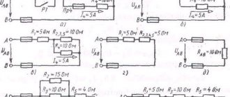
For example, in this circuit there are two resistors.
By default, resistance without a prefix is written only as a number. R2 has a resistance of 220 Ohms. And R3 has a letter after the number. The resistance of this resistor reads 2.2k ohms (2,200 ohms).
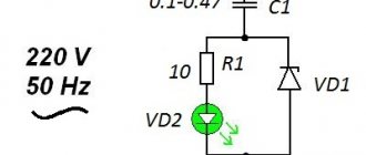
Consider two capacitors in the diagram.
In this case, C5 is a non-polar capacitor with a capacitance of 0.01 µF. Microfarads can be designated either uF or uF. And capacitor C6 is polar and electrolytic. This is indicated by the plus sign near the UGO. Capacitance C6 is 470 μF. The rated operating voltage is indicated in volts. Here for C6 it is 16 V.
Nanofarads are denoted as nF.
If there is no microfarad (uF) or nanofarad (nF) prefix on the circuit, then the capacitance of this capacitor is measured in picofarads (pF, pF). This condition is not common, so carefully study the diagram you are about to read or assemble. There are few capacitances in farads (F), so µF, nF and pF are used.
What is a datasheet and why is it needed?
Datasheet is a technical specification that provides complete information about a radio component. All technical information, basic connection diagram, parameters and types of housings are indicated in this document.
Datasheets come in different languages, mostly in English. There are also translated versions.
Documentation for the NE555 chip. The body and appearance of the part are drawn.
The microcircuit, its parameters and operating conditions are described in detail here.
Such documentation is available for any detail. This is very convenient and informative, especially when searching for analogues. And with the help of the Internet, searching for analogue parts or diagrams has become even easier.
The datasheet also allows you to identify an unknown part or microcircuit. Just write its name in a search engine, add the word datasheet, and all the documentation will be in the search results.
A little history
Now the vast majority of electronic components on the market are manufactured by foreign manufacturers. In the Soviet Union it was the other way around: in the manufacture of electronics, mostly domestic components were used.
For each component, the manufacturer supplied technical specifications (TS), which could only be found in factories where electronic equipment was manufactured. They were not freely available.
The technical specifications contained everything (and even more) that is available in current datasheets. There were paper reference books that contained the most necessary information, which were easier to find.
Now any data sheets can be found very easily. The need for thick paper reference books has disappeared.
How to learn to read circuit diagrams
There are really only a few ways. This is theory and practice. If you learn the designation of radio components, this does not mean that you have learned circuit design. It's like learning your ABC's, but without grammar and practice you won't learn the language.
Theory is circuit design, books, a description of the principle of operation of the circuit. Practice involves assembling devices, repairing and soldering.
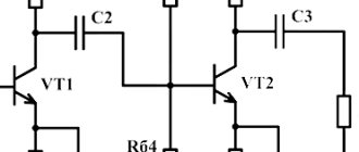
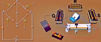
For example, a simple amplifier circuit with one transistor.
Input X1 plus (left or right channel), X2 minus. The sound signal is sent to electrolytic capacitor C1. It protects transistor VT1 from short circuiting, since transistor VT1 is constantly open using a voltage divider across R1 and R2. The voltage divider sets the operating point at the base of transistor VT1, and the transistor does not distort the input signal. Resistor R3 and capacitor C2, which are connected to the emitter of transistor VT1, perform the function of thermal stabilization of the operating point as the temperature of the transistor increases. Electrolytic capacitor C3 accumulates and filters the supply voltage. The BF1 dynamic head serves as an audio signal output.
Is it possible to understand this only by learning the designations of radio components without circuit design and theory? Unlikely.
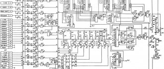
The situation is even more complicated with digital technology.
What kind of microcontroller is this, what functions does it perform, what firmware and what fuses are installed in it? And the second microcircuit, what amplifier is it? Without datasheets and a description of the circuit, it will not be possible to understand its operation.
Study circuit design, theory and practice. Simply learning the names of the parts will not help you understand the circuitry. The designation of radio components can be learned on its own with practice and accumulation of knowledge. It all depends on the chosen industry. Signalmen have one circuit design, mobile equipment repairmen have another. And those who deal with sound will not really understand electricians. As well as vice versa. To understand another industry, its circuitry and operating principles, you need to immerse yourself in it.
Circuit diagrams are a kind of language that has different dialects.
Therefore, one should not create illusions. Study circuit design and assemble circuits.
Schematic diagrams help to assemble devices, and when studying the theory, to understand the operation of the device. Without knowledge and experience, a diagram is just a diagram.
Search Maxim datasheet on the international stock website
1) Go to the stock site, for example, Avnet: 2) Enter the batch number of the microcircuit in search field 1 and click on the search icon 2. In field 3, the system recommends possible variants of the component.
3) In the search results, we look for the version of the batch number we need and click on its name and go to the detailed description of the Maxim chip:
4) In the product card, find the Datasheet icon and click on it.
5) As a result, the file will be saved on your computer.