Most popular models
Currently, the most popular generators are models from, U-Polemag, Vega, and Verano-Co.
They occupy a large part of the device market. Vega produces devices that operate on the principle of magnetic induction. This idea was realized by the famous physicist Adams. The price often depends on the power and size of the device. The minimum cost is 45 thousand rubles. This manufacturer has a number of advantages:
- Products from are very environmentally friendly.
- The generators are completely silent, which allows them to be installed anywhere.
- The devices are relatively compact.
- The manufacturer has quite a few models, the power of which starts from 1.5 kW and reaches up to 10 kW.
"Verano-Co" is a Ukrainian manufacturer that uses only high-quality components for its products. It produces generators for both domestic and industrial purposes. The operating principle of the alternative energy source is the same as that of other magnetic units. The cheapest model costs 50 thousand rubles. Prices for devices reach 200 thousand rubles.
U-Polemag is a Chinese manufacturer. Represents the largest variety of generator models. The standard efficiency of the devices is 93%. Maximum energy loss is 1%. Often purchased for household use. It has compact dimensions, low noise level and light weight. The package includes cooling systems. The maximum duration of use reaches 15 years. Prices for the model range start from 30 thousand rubles. and reach 90 thousand rubles.
Energizistem produces vertical devices. Consumers do not have a clear opinion about the quality and power of devices. Prices for generators are a little high and start at 50 thousand rubles.
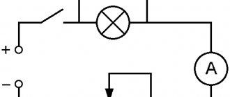
Power supply circuit
For the initial start-up, a circuit is required that supplies a pulse of energy to the Tesla generator transformer. Next, the generator switches to self-oscillating mode and does not constantly need external power.
In developer slang, the power supply device is called a “kacher”. Those familiar with electronics know that the correct name for the device is a blocking oscillator (shock oscillator). Such a circuit solution generates a single powerful electrical impulse.
Many variants of blocking generators have been developed, which are divided into three groups:
- On vacuum tubes;
- On bipolar transistors;
- On field-effect transistors with an insulated gate.
A tube electromagnetic generator using powerful generator tubes operates with high output parameters, but its design is hampered by the availability of components. In addition, not two, but three winding transformers are required, so tube blocking oscillators are now rare.
Tube blocking generator
The most widely used devices are those based on bipolar transistors. Their circuitry is well developed, setup and adjustment are simple. We use domestically produced transistors of the 800 series (KT805, KT808, KT819), which have good technical parameters, are widespread and do not cause financial difficulties.
Blocking oscillator based on a bipolar transistor
The proliferation of powerful and reliable field-effect transistors has made it possible to design blocking oscillators with increased efficiency due to the fact that MOSFET or IGBT transistors have better parameters for voltage drop across transitions. In addition to increasing efficiency, the problem of cooling transistors becomes less problematic. Proven circuits use IRF740 or IRF840 transistors, which are also inexpensive and reliable.
Field effect transistor circuit
Before assembling the generator into a finished structure, double-check the workmanship of all components. Assemble the structure and supply power to it. The transition to self-oscillating mode is accompanied by the presence of voltage on the windings of the transformer (at the output of the secondary). If there is no voltage, then it is necessary to adjust the frequency of the blocking generator in resonance with the frequency of the transformer.
Important! When working with a Tesla generator, extreme caution must be exercised, since when starting, high voltage is induced in the primary winding, which can lead to an accident.
Assembling the device
The device can be assembled either on a printed circuit board or by surface mounting in compliance with the rules for RF mounting. The topology and type of my board are shown below: This board is designed for a transistor type MRF19125 or PTFA211801E . For it, a hole is cut in the board corresponding to the size of the source (heat sink plate). One of the important points in assembling the device is to ensure heat removal from the source of the transistor. I used various radiators to suit the size. For short-term experiments, such radiators are sufficient. For long-term operation, you need a radiator of a sufficiently large area or the use of a fan circuit. Turning on the device without a radiator is fraught with rapid overheating of the transistor and failure of this expensive radio element.
For experiments, I made several generators with different transistors. I also made flange mounts for the stripline resonators so that they could be changed without constantly heating the transistor. The photographs below will help you understand the installation details.
Flange for mounting resonators RF generator with replaceable resonators
HF generator with replaceable resonators The HF generator operates even at a voltage of 3.6 volts, consuming a current of 2.5A. The back side of the HF generator is a piece of PCB - also a resonator))) Flange for a replaceable resonator RF generator on a small MOSFET MRF284 with removable 875 MHz resonators. 5W. without much stress...
RF generator on a small MOSFET MRF284 with removable resonators A family of RF generators on MOSFET transistors of various powers
Removal of resonator energy to the gate using a capacitor
Two-transistor RF multivibrator
Modulator for RF generator
Experiments with a two-transistor RF multivibrator Modulator-multivibrator-ballast resistance Powerful generator-multivibrator using transistors PTFA211801
Small generator on MRF284 1300-1500 MHz. Small generator on MRF284 1300-1500 MHz.
Small generator on MRF284 1300-1500 MHz. Sandwich of 3 transistors MRF19125 Experimental RF generator based on 3 MOSFET transistors
Experimental RF generator based on 3 MOSFET transistors
Experimental RF generator based on 3 MOSFET transistors
Experimental RF generator based on 3 MOSFET transistors Self-oscillator - multivibrator Collector board of a three-transistor generator
Checking the operation of the RF generator on PTFA211801E. 6.5 V at a current of 4.6 A. HF generator with a resonator with an organic glass insert (to fix the shape of the resonant plates).
Checking the operation of the RF generator.
Powerful RF generator board with a cutout for a MOSFET transistor.
The back side of the HF generator: switching, fuse, capacitors and radiator RF generator board, view from the main installation side. RF multivibrator + amplifier
RF multivibrator + MOSFET amplifier Oscillator board 950-1100 MHz Oscillator 950-1100 MHz (experimental)
Principle of operation
To understand the main principle by which such devices operate, you first need to remember one rule - the voltage at each point of the device is directly proportional to the square of the current that flows through the conductor. When an electric current appears, a field always appears around the latter. It is capable of spreading its effect over long distances. It is easy to create free energy in the Romanov generator according to the instructions with your own hands.
The circuit is provided by a constant pumping of energy from an external source. It is formed due to alternating HF current. The result is that the field begins to pulsate and spread its signal. Energy characteristics thus appear in kinetic form. If you force this process, you can get an interesting ethereal effect. It manifests itself as a wave with a powerful shock characteristic. Electromagnetic installations work differently.
Interesting. The situation is conducive to the transition to high-capacity operations.
Tesla generators are devices in which this process can be implemented. A natural analogue is the ethereal discharge of lightning; electric generators can also create such energy.
Free electricity from magnets
How does a frequency generator work?
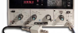
In order to observe the waveform produced by the frequency generator, we will use a digital oscilloscope.
So, we want to get a sinusoidal signal with a frequency of 2 MHz and an amplitude of 5 Volts. To do this, I set the frequency on my generator to 2 MHz, sine, signal swing to 10 Volts. Peak-to-peak = 2 signal amplitudes.
and I get this oscillogram. As you can see, the frequency generator did its job perfectly.
Triangle signal
square wave
DIY Tesla generator for 220 volts
Materials:
- dielectric base for the screen (thick cardboard, plastic panel, plywood);
- foil material;
- the wire;
- electrolytic capacitor (voltage from 180 to 400 V);
- To regulate the voltage, it is possible to install a resistor (resistance).
A similar set of materials is almost always available in the house.
Grounding
It is enough to connect the wire to a metal rod and bury it in the ground. At the dacha, you can throw a wire on any metal pipe in the ground. In the apartment, the wire is connected to water supply pipes, gas metal pipes, and the grounding phase in the socket.
Tesla generator screen
Receives light radiation with positively charged particles from sources (from a light source, the sun).
It’s not difficult to make; just cover the dielectric panel with foil. The layers are overlapped. The larger the screen is to trap positively charged particles, the higher the voltage in the circuit. Several shielded surfaces are also connected to each other. They form a chain of screens for Tesla's fuel-free generator. According to the expansion of the area of the collecting panels, it is necessary to increase the capacitance of the capacitor and the dissipation power of the resistor.
It is necessary to connect and connect the elements of the Tesla fuel-free generator circuit. One wire (contact) is connected to the foil screen, the second leads from grounding. The contacts are closed at the poles of the capacitor. The moment the circuit is closed, the battery begins charging.
Materials for fuel-free Tesla generator
Tesla's fuel-free generator is ready. You can check it by connecting the contacts of the light bulb to a battery, it will light up.
Push-pull generator for hard workers
The other generator that we will consider is also a push-pull generator. However, it contains an oscillatory circuit, which makes its parameters more stable and predictable. Although, in essence, it is also quite simple.
Here he is
What do we see here?
We see the oscillatory circuit L1 C1, And then we see a pair for each creature: Two transistors: VT1, VT2 Two feedback capacitors: C2, C3 Two bias resistors: R1, R2
An experienced eye (and not a very experienced one) will find in this circuit similarities with a multivibrator. Well, that’s how it is!
What is special about this scheme? Yes, because due to the use of push-pull switching, it allows you to develop double power, compared to circuits of 1-cycle generators, at the same supply voltage and provided that the same transistors are used. Wow! Well, in general, she has almost no flaws