2.11. Design parameters of complex loads
When calculating short-circuit currents from complex loads, their parameters of direct, negative and zero sequences should be taken into account. Recommended values of line resistance ( Z
1) and reverse (
Z
2) sequences of individual elements of the complex load are given in table.
1. The values of the impedance modules of the direct ( Z
1НГ), reverse (
Z
2НГ) and zero (
Z
0НГ) sequences of some load nodes, depending on their composition, can be determined as indicated in the appendix. Z.
In approximate calculations for units containing up to 70% asynchronous motors, it is allowed to take the values of the complex load impedance modules equal to = = 0.4; = 3.0.
Table 1
Parameters of complex load elements
| Complex load consumers | Symbols on diagrams | Cos jnom | Resistance values, rel. units | |
| Asynchronous electric motors | HELL | 0,8 | 0,07 + j 0,18 | 0,07 + j 0,18 |
| Synchronous electric motors | SD | 0,9 | 0,03 + j 0,16 | 0,03 + j 0,16 |
| Incandescent lamps | LN | 1,0 | 1,0 | 1,33 |
| Gas discharge light sources | LH | 0,85 | 0,86 + j 0,53 | 0,38 + j 0,24 |
| Converters | P | 0,9 | 0,9 + j 0,44 | 1,66 + j 0,81 |
| Electrothermal installations | EU | 0,9 | 1 + j 0,49 | 0,4 + j 0,2 |
2.4. Active and inductive resistance of cables
The values of the parameters of positive (reverse) and zero sequence of cables used in electrical installations up to 1 kV are used as specified by the manufacturer or in the appendix. B.
When determining the minimum value of the short-circuit current, it is recommended to take into account the increase in the active resistance of the cable at the time of disconnection of the circuit due to heating of the cable by the short-circuit current. The value of the active resistance of the cable in millioms, taking into account its heating by short-circuit current (), is calculated using the formula:
(7)
where is a coefficient that takes into account the increase in the active resistance of the cable (for approximate calculations, the value of the coefficient can be taken equal to 1.5); – active resistance of the cable at a temperature equal to plus 20 °C, mOhm.
2.7. Active and inductive resistances of current transformers
When calculating short-circuit currents in electrical installations with voltages up to 1 kV, one should take into account both the inductive and active resistance of the primary windings of all multi-turn instrument current transformers that are present in the short-circuit circuit. The values of active and inductive zero-sequence resistances are taken equal to the values of positive-sequence resistances. The parameters of some multi-turn current transformers are given in the appendix. D. The active and inductive resistance of single-turn transformers (for currents more than 500 A) can be neglected when calculating short-circuit currents.
2.2. Active and inductive reactance of reactors
Active resistance of current-limiting reactors ( r
1p =
r
2p =
r
0p) in milliohms is calculated using the formula:
(5)
where D P
R. nom – active power losses in the reactor phase at rated current, W; Iр. nom – rated current of the reactor, A.
Inductive reactance of reactors ( x
1p =
x
2p =
x
0p) in milliohms is taken as specified by the manufacturer, or calculated using the formula:
(6)
where w
– angular frequency of the network voltage, rad/s;
L
– inductance of the three-phase reactor coil, H;
M
– mutual inductance between the phases of the reactor, H.
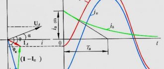
and synchronous electric motors
When calculating the initial value of the periodic component of the short-circuit current, autonomous sources, as well as synchronous electric motors, should be taken into account by the subtransient resistance along the longitudinal axis of the rotor (), and when determining the decay time constant of the aperiodic component of the short-circuit current - by the inductive reactance for negative sequence currents x
2 and the active resistance of the stator winding
r
.
For approximate calculations, take: = 0.15; x
2 = ; r = 0.15.
Checking the response time of the machine in 0.4 kV networks
In most cases, cable line protection is carried out by automatic switches (or, as they are usually called, circuit breakers). The circuit breaker protects the cable line in two ways: from overload (thermal cut-off) and from short circuit (electromagnetic cut-off).
And if you are faced with the problem of choosing the right circuit breaker, then choosing it based on overload is quite simple. You know (or can calculate) the load current. The rating of the circuit breaker must be greater than the load current. This one is simple.
We’ve sorted out the machine’s rating, all that remains is to select its response characteristics. In total, there are five characteristics of the operation of the machine: B, C, D, K, Z. Machines with operation curves K and Z are very rarely used; machines with operation characteristics B, C, D are mainly used. The most common are machines with characteristic C. Operation curves They have a similar shape and differ only in the magnitude of the electromagnetic cutoff or the frequency of operation. The operation frequency is the ratio of the emergency current value at which the machine is switched off to the rated current of the machine. Ik/Inom. For machines with characteristic B, this value ranges from 3...5. For machines with characteristic C - 5...10. For machines with characteristic D - 10...20.
Let's consider a machine with characteristic C. The manufacturer guarantees that the machine will operate if the short circuit current exceeds the rated current of the machine by 10 times. But it can also work when exceeded by 5 times. It depends on external conditions: ambient temperature; whether the circuit breaker was under load when the short circuit occurred, or was it turned off and turned on for short circuit from a “cold” state.
What happens if the short circuit current is less than the cutoff? The machine may still turn off, because... The thermal cut-off will already work. But this will not happen instantly, but after some time. The permissible response time of the machine is strictly regulated by the Electrical Installation Rules (PUE) and depends on the value of the phase voltage. According to the requirements of clause 1.7.79, the maximum permissible protective automatic shutdown time at a phase voltage of 220/230 V for a TN grounding system should not be more than 0.4 s.
So, it is necessary to check the tripping time of the circuit breaker. This calculation is also called “phase-zero loop calculation”. For example, let's check a machine with a rated current of 16 A with characteristic C. The machine is installed in a group switchboard. The panel is powered by the main switchboard, and the main switchboard by the transformer substation.
Transformer parameters: Rated power of the transformer Sn = 630 kVA, Short circuit voltage of the transformer Uk% = 5.5%, Short circuit loss of the transformer Pk = 7.6 kW.
Supply line parameters: Gr.27 from ShchO 1.2 – 60 m cable 1x[VVGng LS 3×2.5], ShchO 1.2 from GrShch3 – 80 m cable 1x[AVVGng LS 5×50], GrShch3 from TP 1126 – 217 m cable AVVGng 2x (4×185).
Switch parameters: Rated current of the circuit breaker Inom = 16 A Cut-off ratio K = 10.
Transformer reactance: Xt = 13.628 mOhm
Transformer active resistance: RT = 3.064 mOhm
Active cable resistance: Rк = 580.38 mOhm
Cable reactance: Xk = 17.36 mOhm
Power system resistance: Xc = 1.00 mOhm
Total reactance of the section: XΣ=Xc+Xт+Xк=31.984 mOhm
Total active resistance of the section: RΣ=Rt+Rk=583.444 mOhm
Total total resistance: RΣ=583.444 mOhm
Single-phase short circuit current: IK1=190 A > IminK1 = 10×16 = 160 A Therefore, the circuit breaker will turn off instantly (electromagnetic cut-off will work, shutdown time.
To calculate in Word, click on the button:
In order not to count manually on a calculator each time and transfer the numbers to Microsoft Word, I implemented these calculations directly in Word. Now you just need to answer the questions he asks. This is what it looks like:
The entire calculation took two and a half minutes.
Subscribe and receive notifications of new articles by e-mail
power transformers
Active and inductive resistance of positive sequence of step-down transformers ( r
t,
x
t) in milliohms, reduced to the lowest voltage stage of the network, are calculated using the formulas:
(3)
(4)
where is the rated power of the transformer, kV×A; – short circuit losses in the transformer, kW; – rated voltage of the low voltage winding of the transformer, kV; And
k – short circuit voltage of the transformer, %.
Active and inductive zero-sequence resistances of step-down transformers, the windings of which are connected according to the D/ Y
0, when calculating a short circuit in a low voltage network, it should be taken equal to the active and inductive positive sequence resistances, respectively. For other connection schemes of transformer windings, active and inductive zero-sequence resistances must be taken in accordance with the manufacturers' instructions.
2.10. Parameters of asynchronous electric motors
When calculating the initial value of the periodic component of the short-circuit current from asynchronous electric motors, the latter should be introduced into the equivalent circuit with a subtransient inductive reactance. If it is necessary to carry out refined calculations, the active resistance of the stator must also be taken into account. It is recommended to determine the values of asynchronous motors as indicated in the appendix. G. For approximate calculations, the following are taken: supertransient inductive reactance of an asynchronous motor = 0.18; active stator resistance of an asynchronous motor = 0.36.
ads
retriever writes:
1. because mega is 1000,000, and kilo is 1000. dividing a million by a thousand we get what? thousand. 2. look at what the dog is powered from. if it is a step-down transformer, then consider its resistance, this is the system resistance. if this is a cable from another PS, look for the power supply unit in the diagram, take the resistance of the transformer there and add the resistance of the cable to it. In my opinion, it is better to take into account the active component of the cable resistance, it is large
Thank you! But I still don't understand. Here is my calculation, please tell me where I am wrong. It seems like I’m doing everything by the book.
Added: 2018-09-28 12:25:57
Added: 2018-09-28 12:27:01
Good day! Still, I found some of the books I was looking for and began to study. By coincidence, I am the only “relay guy” in this office. The management gave the task, they say, a new gas power plant is being built, you will service it, and you will calculate the settings! I honestly admit that, except in technical school, I have never had to calculate short-circuit currents anywhere, with the exception of several attempts that were outlined on this forum (but nothing came of it). I looked at the single-line diagram and decided to start calculations with the simplest cell (in my opinion), this is the cell feeding the TSN. I immediately figured out the set of necessary protections (cut-off, MTZ, reload, dugout) and decided that I had made the right choice. I opened M.A.’s book. Shabad “Protection of 10 kV transformers”, and began to plunge into the world of “high matters”. Okay, let’s move away from the lyrics and begin to outline the essence of my calculations (looking ahead, I’ll say that the problem arose already in the second formula). From the book by M.A. Shabad “Protection of 10 kV transformers” “Calculation of three-phase short-circuit current from the value of the short-circuit voltage of the transformer. Most simply, the maximum current value (in amperes) of a three-phase short circuit behind a transformer is calculated from the value of the short-circuit voltage of the transformer: I(3)k=100*Inom. tr/Uk+r; where Uk is the short-circuit voltage from the passport in %; Inom.tr - nom. tr-ra current on the LV or HV side from the passport; p=100*Snom/Sk where Snom is nom. tr-ra power Sk - the power of a three-phase short circuit of the supply power system at the point where the transformer is connected, i.e. at its HV terminals, if the power of the power system is relatively high, then p=0.” Further in the book there are examples of calculations, but in all examples he uses the value Sk = 100 MVA (apparently an arbitrary value). I started looking for where to get this value, how to calculate it, or ask someone). I came across the textbook “Calculation of short circuit currents and testing of electrical equipment” by S.V. Khavronichev, I. Yu. Rybkina (I don’t know if this is an advertisement or not), so it says there: “For practical calculations, it is important to determine whether in this particular case the supply system can be considered a system of unlimited power. If the total power of the system generators is known, but if one of the conditions is met Xc*S/U^2<=3; Sc/S(3)<=3; where U is the phase-to-phase voltage of the system, kV; S(3) — three-phase short circuit power on substation buses, MVA; Sc—system power, MVA; Xc is the system resistance, Ohm, I take the system to be a system of unlimited power.” Well, I think that’s it, now I’ll plug in the numbers and that’s it, it’s all in the bag. I took a closer look at the formulas, S(3) is unknown, which means that the second inequality cannot be verified, and I began to study the first formula. 11 gas compressor units with a capacity of 2148 KVA and a rated voltage of 6.3 kV will be installed. It remains to find out Xs. I searched the Internet and why I came to the conclusion that Xc is the same as X”d, because 11 GPUs operate in parallel, making up an equivalent circuit, we get 0.015 (since X"d of one generator is 0.16). I substituted the obtained values into the formula: 0.015*(2.148*11)/6.3^2=0.0089 < 3; To be honest, the result confused me, but you can’t argue with the numbers. Later I found one formula for calculating Xc Xc= X»d*Sb/Sn Xc=0.16*(2148*11)/2148=1.76 (since 11 GPUs work in parallel, making up the equivalent circuit we get 0.16) 0, 16*(2.148*11)/6.3^2=0.095 < 3 So we think that the system has infinite power?! (is this correct?) Let's go back to M.A.'s book. Shabad “Protection of 10 kV transformers” Inom.in = S/(1.73*U)=1000/(1.73*6.3)=91.75 A Inom.nn = S/(1.73*U)=1000/(1.73*0.4) =1445.1 A I(3)k=100*Inom. tr/Uk+r= I(3)k=(100*91.75)/(6+0)=1529.17A; I(3)k=100*Inom. tr/Uк+р= I(3)к=(100*1445.1)/(6+0)=24085А; Too big numbers confuse me! But the book provides a second method of calculation: From the book by M.A. Shabad “Protection of 10 kV transformers” “Calculation of three-phase short-circuit current from the transformer impedance Ztr. The value of this resistance and its components: active Rtr and inductive Xtr. …. The transformer impedance Ztr is determined by: Ztr=Uk*Unom^2/(100*Snom)=6*6.3^2/100*1000=0.00238 I(3)=Uav/(1.73*Ztr)=6300/ (1.73*0.00238)=1536585 A According to the idea, the calculations I(3)= 1536585 A and I(3)k=1529.17A should be equal, but you can see for yourself! Next comes the calculation of the short circuit in the minimum mode, but that’s a completely different story...
Please help me figure all this out! I understand, of course, that it’s easiest to write “read the textbook,” but I think everyone present here (or the majority) learned experience from their mentors and colleagues, but it so happened that I have no one to take experience from, but a dry text from “ textbook" is not always easy to understand. In general, don’t judge strictly, I just want to learn!
Post's attachments IMG_20180401_093818.jpg
3.11 MB, 3 downloads from 2018-04-01
You don't have the permssions to download the attachments of this post.
don't judge too harshly), I'm just learning!