Code marking
According to IEC standards, in practice there are four ways to encode the nominal capacity.
Three digit encoding
The first two digits indicate the capacitance value in picofarads (pF), the last two digits indicate the number of zeros. When the capacitor has a capacitance of less than 10 pF, the last digit may be "9". For capacitances less than 1.0 pF, the first digit is “0”. The letter R is used as a decimal point. For example, code 010 is 1.0 pF, code 0R5 is 0.5 pF.
Table 1
* Sometimes the last zero is not indicated.
Four digit encoding
4-digit coding options are possible. But even in this case, the last digit indicates the number of zeros, and the first three indicate the capacity in picofarads (pF).
table 2
Capacitance marking in microfarads
The letter R may be used instead of the decimal point.
Mixed alphanumeric marking of capacity, tolerance, TKE, operating voltage
Unlike the first three parameters, which are marked in accordance with standards, the operating voltage of different companies has different alphanumeric markings.
Examples:
Picture 1
How are large capacitors marked?
To correctly read the technical specifications of a device, some preparation is necessary. You need to start studying with units of measurement. To determine capacitance, a special unit is used - farad (F). The value of one farad for a standard circuit seems too large, so household capacitors are marked in smaller units. The most commonly used is mF = 1 µF (microfarad), which is 10-6 farads.
In calculations, an off-label unit can be used - millifarad (1mF), which has a value of 10-3 farads. In addition, designations can be in nanofarads (nF) equal to 10-9 F and picofarads (pF) equal to 10-12 F.
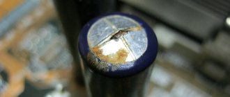
Capacitance markings for large capacitors are applied directly to the housing. In some designs, the markings may differ, but in general, you need to be guided by the units of measurement mentioned above.
Designations are sometimes written in capital letters, for example, MF, which actually corresponds to mF - microfarads. The marking fd is also found - an abbreviated English word farad. Therefore mmfd will correspond to mmf or picofarad. In addition, there are designations that include a number and one letter. This marking looks like 400m and is used for small capacitors.
In some cases, it is possible to apply tolerances, which are an acceptable deviation from the rated capacitance of the capacitor. This information is of great importance when, when assembling certain types of electrical circuits, capacitors with precise capacitance values may be required. If we take the marking 6000uF + 50%/-70% as an example, then the maximum capacitance value will be 6000 + (6000 x 0.5) = 9000 µF, and the minimum 1800 µF = 6000 – (6000 x 0.7).
Color coding
In practice, several color marking techniques are used to color code permanent capacitors.
* Tolerance 20%; a combination of two rings and a dot indicating a multiplier is possible.
** The color of the housing indicates the operating voltage.
The “+” terminal may have a larger diameter.
To mark film capacitors, 5 colored stripes or dots are used:
The first three encode the value of the nominal capacitance, the fourth - the tolerance, the fifth - the rated operating voltage.
Some notes and tips on working with capacitors
It must be remembered that capacitors with a higher rated voltage should be selected as the ambient temperature increases, creating a larger voltage reserve to ensure high reliability. If the maximum constant operating voltage of the capacitor is specified, this refers to the maximum temperature (unless otherwise stated). Therefore, capacitors always operate with a certain margin of safety. And yet, it is desirable to ensure that their actual operating voltage is at a level of 0.5-0.6 nominal.
If a limit value for alternating voltage is specified for a capacitor, then this applies to a frequency of (50-60) Hz. For higher frequencies or in the case of pulsed signals, the operating voltages should be further reduced to avoid overheating of the devices due to dielectric losses. High-capacity capacitors with low leakage currents are able to retain the accumulated charge for a long time after the equipment is turned off. To ensure faster discharge, for greater safety, you should connect a resistor with a resistance of 1 MOhm (0.5 W) in parallel with the capacitor.
Related material: How to connect a capacitor
TKE marking
Capacitors with non-standardized TKE
* Modern color coding. Colored stripes or dots. The second color can be represented by the color of the body.
Capacitors with linear temperature dependence
* The actual spread for imported capacitors in the temperature range -55...+85'С is shown in brackets.
** Modern color coding. Colored stripes or dots. The second color can be represented by the color of the body.
Capacitors with nonlinear temperature dependence
* Designation according to EIA standard, IEC in parentheses.
**Depending on the technologies that the company has, the range may be different.
For example, the PHILIPS company for the Y5P group normalizes -55...+125 °C.
***According to EIA. Some companies, such as Panasonic, use a different encoding.
Features of coding capacitors made in the USSR
In the USSR, IEC standards were followed, so you can use the above data, but there were also minor differences.
The coded designation of nominal capacities consists of two or three numbers and a letter. The code letter is a multiplier that makes up the capacitance value (see table) and determines the position of the decimal fraction.
The permissible deviation of the capacitance value as a percentage of the nominal value is indicated by the same letters as the tolerances for the resistance of resistors, however, with some additions (see table). For capacitors with a capacitance of less than 10 pF, the permissible deviation is set in picofarads :
Capacitors are marked with a code in the following order:
- rated capacity;
- permissible deviation of capacity;
- TKE and (or) rated voltage.
Here are examples of coded marking of capacitors.
The abbreviated alphanumeric marking on the 33pKL capacitor indicates a nominal capacitance of 33 pF with a tolerance of ±10% and temperature instability of the M75 group (75x10-6 °C-1). The inscription m10SF indicates 100 µF (0.1 millifarads) with a tolerance of -20...+50% and a nominal voltage of 20 V.
A nominal capacitance of 150 pF can be designated 150p or n15; 4700pf - 4n7; 0.15 µF - µ15; 2.2μF - 2μ2.
| Capacity | ||
| Factor | Code | Meaning |
| 10-12 | p | picofarads |
| 10-9 | n | nanofarads |
| 10-6 | h | microfarads |
| 10-3 | m | millifarads |
| 1 | F | farads |
Note. The old tolerance designation is indicated in parentheses.
| Eg. IN | Lit. designation | Eg. IN | Lit. designation | Eg. IN | Lit. designation | Eg. IN | Lit. designation | Eg. IN | Lit. designation |
| 1,0 | I | 6.3 | B | 40 | S | 100 | N | 350 | T |
| 2,5 | M | 10 | D | 50 | J | 125 | P | 400 | Y |
| 3.2 | A | 16 | E | 63 | K | 160 | Q | 450 | U |
| 4.0 | C | 20 | F | 80 | L | 315 | X | 500 | V |
Alphanumeric designation
If you disassemble old Soviet equipment, then everything will be quite simple - on the cases it says “22pF”, which means 22 picofarads, or “1000 uF”, which means 1000 microfarads. Old Soviet capacitors were usually large enough to allow such “long texts” to be written on them.
Global, so to speak, alphanumeric marking involves the use of letters of the Latin alphabet:
- p – picofarads,
- n – nanofarads
- m – microfarads.
At the same time, it is useful to remember that if we conventionally take picofarad as a unit of capacity (although this is not entirely correct), then the letter “p” will denote units, the letter “n” – thousands, the letter “m” – millions. In this case, the letter will be used as a decimal point. Here is a clear example, a capacitor with a capacity of 2200 pF, according to this system will be designated 2n2, which literally means “2.2 nanofarads”. Or a capacitor with a capacity of 0.47 µF will be designated m47, that is, “0.47 microfarads”.
It will be interesting➡ Capacitor - in simple words about the complex
Moreover, domestically produced capacitors have similar markings in Cyrillic, that is, picofarads are designated by the letter “P”, nanofarads by the letter “N”, microfarads by the letter “M”. But the principle is the same: 2H2 is 2.2 nanofarads, M47 is 0.47 microfarads. For some types of miniature capacitors, “μF” is designated by the letter R, which is also used as a decimal point, for example:
1R5 =1.5 µF.
Capacitor symbols
In Russia, there is a system of conventional graphic symbols, including the UGO of the capacitor. A separate GOST, which is part of the Unified System of Design Documentation, is dedicated to the visual representation of these devices, as well as resistors. International standards – IEEE – are also used.
Constant capacitor
Such elements are produced with and without polarization. Small non-polarized products have a wide range of applications and can be connected in different directions. In the diagram they are indicated by two parallel short lines located at right angles to the connection lines. The device’s casing indicates its capacity, often without units of measurement (0.1 is 1 microfarad).
Capacitor number code
The first pair of characters shows the capacity, the number after them shows the number of zeros. The unit of measurement is picofarad. Sometimes such markings contain letters; they indicate the percentage tolerance and the rated voltage.
Polarized capacitors
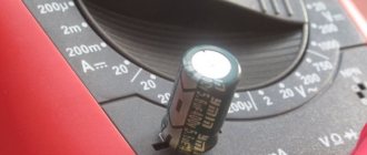
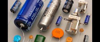
The most common type of polar capacitor element is electrolytic. Such products are produced in the form of cylinders or in axial design. The first option is somewhat more compact and cheaper. Its terminals are located on one side, while the axial options are on different sides. Since the devices are relatively large, the rated voltage (it is relatively low) and capacitance are indicated on their cases.
Important! When connecting these products, the polarity must be strictly observed, otherwise they may malfunction or even explode. This is how polarized elements are shown in diagrams
Tantalum capacitors
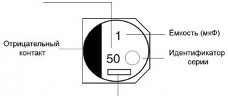
These products are extremely compact; they are used in cases where it is important to minimize dimensions. In the past, they were marked with two colored stripes (each color corresponding to a number) and a speck of white or gray (in the first case, the microfarad value of the stripes was divided by 10, in the second by 100). If you turn the object with the spot facing you, there will be a “plus” pole on the right side
A stripe indicating voltage was also drawn near the terminals. Modern models are marked with digital parameter values
If you turn the object with the spot facing you, there will be a plus pole on the right side. A stripe indicating voltage was also drawn near the terminals. Modern models are marked with digital parameter values.
Variable capacitors
Due to the very low capacitance, these parts have a narrow scope of application - they are mainly used in radio circuits. Graphically, variable elements are represented by the traditional symbol of a pair of short parallels crossed out with an inclined arrow. Capacity is indicated not by a clear number, but by a range.
Capacitor trimmers
These are superminiature products mounted directly on a printed circuit board. Since the capacity indicator changes only during adjustment work, such elements are called tuning elements. The graphical representation differs from the standard one for variable capacitors only in that instead of a point, the arrow is equipped with a perpendicular dash.
This product has a two-layer structure and a fairly large capacity (up to 10 F). At the interface of the electrode surface and electrolyte in such devices, a space of static charge carriers appears. Unlike electrolytic variations, the method of storing energy here is an electrostatic field. The combination of a large surface area and a small thickness of space provides such a high capacity value. Denoted as a symbol of a capacitor element with a vertical line perpendicular to it, placed in a circle. At the same time, in the upper right and lower left quarters, into which the symbol and vertical divide the circle, there are lines similar to the graph of a half-sine wave.
Polymer solid capacitors
All devices of this type can be said to be polymer because the inside of this device uses a solid polymer instead of a liquid electrolyte. The use of solid material in standard solid capacitors has provided the following advantages:
- at high frequencies - low equivalent resistance;
- high ripple current;
- the service life of the capacitor is significantly longer;
- more stable operation at high temperatures.
In more detail, for example, lower ESR means lower energy consumption, which means less heating of the capacitor under the same loads. A higher degree of current ripple ensures stable operation of the entire board as a whole. Naturally, it was the replacement of the liquid electrolyte with a solid one that led to the fact that the service life increased significantly.
By appearance
If the markings are worn out or unclear, determining the polarity of the capacitor is sometimes possible by analyzing the appearance of the case. In many containers with terminals located on one side and not mounted, the positive leg is longer than the negative leg. Products of the ETO brand, now obsolete, look like 2 cylinders placed on top of each other: a larger diameter and small height, and a smaller diameter, but significantly higher. The contacts are located in the center of the ends of the cylinders. The positive terminal is mounted at the end of a cylinder with a larger diameter.
For some powerful electrolytes, the cathode is located on the body, which is connected by soldering to the chassis of the electrical circuit. Accordingly, the positive terminal is isolated from the housing and located on its upper part.
The polarity of a wide class of foreign, and now domestic, electrolytic capacitors is determined by the light stripe associated with the negative pole of the device. If the polarity of the electrolyte cannot be determined either by the markings or by its appearance, then even then the problem of “how to find out the polarity of a capacitor” is solved by using a universal tester - a multimeter.