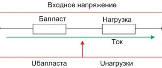
A switching power supply is an inverter system in which the input AC voltage is rectified, and then the resulting DC voltage is converted into pulses of high frequency and a set duty cycle, which are usually supplied to a pulse transformer.
Pulse transformers are manufactured according to the same principle as low-frequency transformers, only the core is not steel (steel plates), but ferromagnetic materials - ferrite cores.
Rice. How does a switching power supply work?
The output voltage of the switching power supply is stabilized , this is done through negative feedback, which allows you to keep the output voltage at the same level even when the input voltage and load power at the output of the unit changes.
Negative feedback can be implemented using one of the additional windings in the pulse transformer, or using an optocoupler that is connected to the output circuits of the power source. The use of an optocoupler or one of the transformer windings allows for galvanic isolation from the alternating voltage network.
The main advantages of switching power supplies (SMPS):
- low weight of the structure;
- small sizes;
- high power;
- high efficiency;
- low cost;
- high stability;
- wide range of supply voltages;
- many ready-made component solutions.
The disadvantages of SMPS include the fact that such power supplies are sources of interference, this is due to the operating principle of the converter circuit. To partially eliminate this drawback, shielding of the circuit is used. Also, due to this disadvantage, in some devices the use of this type of power supply is impossible.
Switching power supplies have become virtually an indispensable attribute of any modern household appliances that consume power from the network in excess of 100 W. Computers, televisions, and monitors fall into this category. To create switching power supplies, examples of specific implementations of which will be given below, special circuit solutions are used. Thus, to eliminate through currents through the output transistors of some switching power supplies, a special form of pulses is used, namely, rectangular bipolar pulses with a time interval between them.
The duration of this interval must be greater than the time of resorption of minority carriers in the base of the output transistors, otherwise these transistors will be damaged. The width of control pulses can be changed using feedback to stabilize the output voltage. Typically, to ensure reliability in switching power supplies, VU transistors are used, which, due to technological features, do not differ for the better (they have low switching frequencies, low current transfer coefficients, significant leakage currents, large voltage drops at the collector junction in the open state).
This is especially true for now outdated models of domestic transistors such as KT809, KT812, KT826, KT828 and many others. It is worth saying that in recent years a worthy replacement for bipolar transistors, traditionally used in the output stages of switching power supplies, has appeared.
These are special high-voltage field-effect transistors of domestic and, mainly, foreign production. In addition, there are numerous microcircuits for switching power supplies.
Adjustable width pulse generator circuit
Bipolar symmetrical pulses of adjustable width can be obtained using a pulse generator according to the circuit in Fig. 1. The device can be used in circuits for auto-regulating the output power of switching power supplies. The DD1 chip (K561LE5/K561 LAT) contains a rectangular pulse generator with a duty cycle of 2.
The symmetry of the generated pulses is achieved by adjusting resistor R1. The operating frequency of the generator (44 kHz), if necessary, can be changed by selecting the capacitance of capacitor C1.
Rice. 1. Circuit of a shaper of bipolar symmetrical pulses of adjustable duration.
Voltage comparators are assembled on elements DA1.1, DA1.3 (K561KTZ); on DA1.2, DA1.4 - output keys. Rectangular pulses are supplied to the inputs of comparator switches DA1.1, DA1.3 in antiphase through forming RC diode chains (R3, C2, VD2 and R6, SZ, VD5).
The charging of capacitors C2, SZ occurs according to an exponential law through R3 and R5, respectively; discharge - almost instantly through diodes VD2 and VD5. When the voltage on capacitor C2 or SZ reaches the operating threshold of the comparator switches DA1.1 or DA1.3, respectively, they are turned on, and resistors R9 and R10, as well as the control inputs of the keys DA1.2 and DA1.4, are connected to the positive pole of the source nutrition. Since the switches are switched on in antiphase, such switching occurs strictly one by one, with a pause between pulses, which eliminates the possibility of through current flowing through switches DA1.2 and DA1.4 and the converter transistors controlled by them, if a bipolar pulse generator is used in a switching power supply circuit.
Smooth control of the pulse width is carried out by simultaneously applying a starting (initial) voltage to the inputs of the comparators (capacitors C2, SZ) from potentiometer R5 through diode-resistive chains VD3, R7 and VD4, R8. The maximum control voltage level (maximum output pulse width) is set by selecting resistor R4. The load resistance can be connected using a bridge circuit - between the connection point of elements DA1.2, DA1.4 and capacitors Ca, Cb. Pulses from the generator can also be supplied to a transistor power amplifier. When using a bipolar pulse generator in a switching power supply circuit, the resistive divider R4, R5 should include a regulatory element - a field-effect transistor, an optocoupler photodiode, etc., which allows, when the load current decreases/increases, to automatically adjust the width of the generated pulse, thereby controlling the output converter power. As an example of the practical implementation of switching power supplies, we provide descriptions and diagrams of some of them.
Operating principle
The operation of a simple design UPS is as follows. If the input current is AC, as in most household appliances, then the voltage is first converted to DC. Some unit designs have switches that double the voltage. This is done in order to connect to a network with different voltage ratings, for example, 115 and 230 volts.
The rectifier equalizes the alternating voltage and outputs direct current, which enters the capacitor filter. The current from the rectifier comes out in the form of small pulses of high frequency. The signals have high energy, which reduces the power factor of the pulse transformer. Due to this, the dimensions of the pulse unit are small.
To correct the decrease in power in new power supplies, a circuit is used in which the input current is obtained in the form of a sine. Blocks are installed in computers, video cameras and other devices according to this scheme. The pulse unit operates from a constant voltage passing through the unit without changing. Such a block is called flyback. If it serves 115 V, 163 volts is needed to operate at constant voltage, this is calculated as (115 × √2).
For a rectifier, such a circuit is harmful, since half of the diodes are not used in operation, this causes overheating of the working part of the rectifier. In this case, durability is reduced.
UPS operation diagram
In network blocks, the input and output are isolated from each other; in pulse blocks, the current is applied to the high-frequency primary winding. The transformer creates the required voltage on the secondary winding.
For output voltages greater than 10 V, silicon diodes are used. At low voltages, Schottky diodes are installed, which have the following advantages:
- Fast recovery, which makes it possible to have small losses.
- Low voltage drop. To reduce the output voltage, a transistor is used; the main part of the voltage is rectified in it.
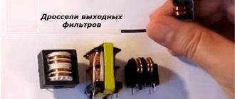
Next, the voltage is smoothed by a filter that includes a capacitor and inductor. Higher switching frequencies require components with low inductance and capacitance.
Minimum size pulse block circuit
In a simple UPS circuit, a choke is used instead of a transformer. These are converters for lowering or increasing voltage; they belong to the simplest class; one switch and a choke are used.
Some types of UPS
- A simple UPS based on IR2153, common in Russia.
- Switching power supplies based on TL494.
- Switching power supplies based on UC3842.
- Hybrid type, from an energy-saving lamp.
- For an amplifier with increased data.
- From electronic ballast.
- Adjustable UPS, mechanical device.
- For UMZCH, highly specialized power supply.
- Powerful UPS with high performance.
- At 200 V - for a voltage of no more than 220 volts.
- 150 watt network UPS, network only.
- For 12 V - works normally at 12 volts.
- For 24 V – works only on 24 volts.
- Bridge – a bridge circuit is used.
- For a tube amplifier - characteristics for tubes.
- For LEDs – high sensitivity.
- Bipolar UPS, distinguished by quality.
- Flyback, has increased voltage and power.
Peculiarities
A simple UPS can consist of small transformers, since as the frequency increases, the efficiency of the transformer is higher and the requirements for core dimensions are smaller. This core is made of ferromagnetic alloys, and steel is used for low frequencies.
The voltage in the power supply is stabilized by negative feedback. The output voltage is maintained at the same level and does not depend on the load and input fluctuations. Feedback is created using different methods. If the block has galvanic isolation from the network, then connection of one winding of the transformer is used at the output or using an optocoupler. If decoupling is not needed, then use a simple resistive divider. Due to this, the output voltage is stabilized.
Features of laboratory blocks
The operating principle is based on active voltage conversion. To remove interference, filters are placed at the end and beginning of the circuit. Saturation of transistors has a positive effect on the diodes, and there is voltage regulation. Built-in protection blocks short circuits. The power cables are used in a non-modular series, the power reaches 500 watts.
The case has a cooling fan, the fan speed is adjustable. The maximum load of the unit is 23 amperes, resistance 3 ohms, maximum frequency 5 hertz.
Application of pulse blocks
The scope of their use is constantly growing both in everyday life and in industrial production.
Switching power supplies are used in uninterruptible power supplies, amplifiers, receivers, televisions, chargers, for low-voltage lighting lines, computer, medical equipment and other various devices and devices for general purposes.
Advantages and disadvantages
The UPS has the following advantages and disadvantages:
- Light weight.
- Increased efficiency.
- Low cost.
- The supply voltage range is wider.
- Built-in safety locks.
The reduced weight and dimensions are due to the use of elements with linear mode cooling radiators and pulse control instead of heavy transformers. The capacitor capacity is reduced by increasing the frequency. The rectification circuit has become simpler; the simplest circuit is half-wave.
Low frequency transformers lose a lot of energy and dissipate heat during transformations. In a UPS, maximum losses occur during transient switching processes. At other times, the transistors are stable, they are closed or open. Conditions have been created for energy conservation, efficiency reaches 98%.
The cost of UPS has been reduced due to the unification of a wide range of elements in robotic enterprises. Power elements from controlled switches consist of semiconductors of lower power.
Pulse technologies make it possible to use power networks with different frequencies, which expands the use of power supplies in various energy networks. Semiconductor modules with small dimensions and digital technology are protected against short circuits and other accidents.
Flaws
Switching power supplies operate by converting high-frequency pulses and create noise that escapes into the environment. There is a need to suppress and combat interference using different methods. Sometimes noise suppression does not have an effect, and the use of pulse blocks becomes impossible for some types of devices.
Replacement must be made only with a permitting tolerance for certain parameters , which you can find for any radio element in specialized literature or in the diagram supplied with the device. This is a safe method, because switching power supplies are very insidious with their electrical discharges.
Switching power supply circuit
The switching power supply (Fig. 2) consists of mains voltage rectifiers, a master oscillator, a rectangular pulse shaper of adjustable duration, a two-stage power amplifier, output rectifiers and an output voltage stabilization circuit.
The master oscillator is made on a K555LAZ type microcircuit (elements DDI .1, DDI .2) and produces rectangular pulses with a frequency of 150 kHz. An RS trigger is assembled on elements DD1.3, DD1.4, the output frequency of which is half as low - 75 kHz. The switching pulse duration control unit is implemented on a K555LI1 type microcircuit (elements DD2.1, DD2.2), and the duration is adjusted using optocoupler U1. The output stage of the switching pulse shaper is assembled using elements DD2.3, DD2.4. The maximum output power of the pulse shaper reaches 40 mW. The preliminary power amplifier is made on transistors VT1, VT2 type KT645A, and the final amplifier is made on transistors VT3, VT4 type KT828 or more modern. The output power of the cascades is 2 and 60...65 W, respectively. A circuit for stabilizing the output voltage is assembled using transistors VT5, VT6 and optocoupler U1. If the voltage at the output of the power supply is below normal (12 V), the zener diodes VD19, VD20 {KS182+KS139) are closed, transistor VT5 is closed, transistor VT6 is open, a current flows through the LED (U1.2) of the optocoupler, limited by resistance R14; The resistance of the photodiode (U1.1) of the optocoupler is minimal.
The signal taken from the output of element DD2.1 and supplied to the inputs of the coincidence circuit DD2.2 directly and through an adjustable delay element (R3 - R5, C4, VD2, U1.1), due to its small time constant, arrives almost simultaneously at the inputs of the circuit matches (element DD2.2).
At the output of this element, wide control pulses are formed. Bipolar pulses of adjustable duration are formed on the primary winding of transformer T1 (outputs of elements DD2.3, DD2.4).
Rice. 2. Switching power supply circuit.
If for any reason the voltage at the output of the power supply increases above normal, current will begin to flow through the zener diodes VD19, VD20, transistor VT5 will open slightly, VT6 will close, reducing the current through the optocoupler LED U1.2.
In this case, the resistance of the photodiode of the optocoupler U1.1 increases. The duration of the control pulses decreases, and the output voltage (power) decreases. When the load is short-circuited, the optocoupler LED goes out, the resistance of the optocoupler photodiode is maximum, and the duration of the control pulses is minimal. Button SB1 is designed to start the circuit. At the maximum duration, positive and negative control pulses do not overlap in time, since there is a time gap between them due to the presence of resistor R3 in the forming circuit.
This reduces the likelihood of through currents flowing through the output relatively low-frequency transistors of the final power amplification stage, which take a long time to absorb excess carriers at the base junction. The output transistors are installed on finned heat sinks with an area of at least 200 cm^2. It is advisable to install resistances of 10...51 Ohms in the base circuits of these transistors. The power amplification stages and the circuit for generating bipolar pulses are powered by rectifiers made on diodes VD5 - VD12 and elements R9 - R11, C6 - C9, C12, VD3, VD4. Transformers T1, T2 are made on ferrite rings K10x6x4.5 ZOOONM; TZ - K28x16x9 ZOOONM. The primary winding of transformer T1 contains 165 turns of PELSHO 0.12 wire, the secondary winding contains 2×65 turns of PEL-2 0.45 (winding in two wires).
The primary winding of the T2 transformer contains 165 turns of PEV-2 0.15 mm wire, the secondary windings contain 2x40 turns of the same wire. The primary winding of the TZ transformer contains 31 turns of MGShV wire, threaded into a cambric and having a cross-section of 0.35 mm^2, the secondary winding has 3 × 6 turns of PEV-2 wire 1.28 mm (parallel connection). When connecting transformer windings, it is necessary to phase them correctly. The beginnings of the windings are shown in the figure with asterisks. The power supply is operational in the mains voltage range of 130...250 V. The maximum output power with a symmetrical load reaches 60...65 W (stabilized voltage of positive and negative polarity 12 S and stabilized AC voltage with a frequency of 75 kHz, removed from the secondary winding of transformer T3) . The ripple voltage at the output of the power source does not exceed 0.6 V. When setting up the power source, the mains voltage is supplied to it through an isolation transformer or a ferroresonant stabilizer with an output isolated from the mains. All resoldering in the source can only be done when the device is completely disconnected from the network.
It is recommended to turn on a 60 W 220 V incandescent lamp in series with the output stage while setting up the device. This lamp will protect the output transistors in case of installation errors. Optocoupler U1 must have an insulation breakdown voltage of at least 400 V. Operation of the device without load is not allowed.
Design features and operating principle
Of the several methods of converting voltage to power electronic components, two that are most widespread can be identified:
- Analog, the main element of which is a step-down transformer, in addition to its main function, it also provides galvanic isolation.
- Impulse principle.
Let's look at how these two options differ.
PSU based on a power transformer
Simplified block diagram of an analog power supply
The next block performs two functions: it smoothes the voltage (a capacitor of appropriate capacity is used for this purpose) and stabilizes it. The latter is necessary so that the voltage does not “drop” when the load increases.
The given block diagram is greatly simplified; as a rule, a source of this type has an input filter and protective circuits, but this is not important for explaining the operation of the device.
All the disadvantages of the above option are directly or indirectly related to the main design element - the transformer. Firstly, its weight and dimensions limit miniaturization. In order not to be unfounded, we will use as an example a step-down transformer 220/12 V with a rated power of 250 W. The weight of such a unit is about 4 kilograms, dimensions 125x124x89 mm. You can imagine how much a laptop charger based on it would weigh.
Step-down transformer OSO-0.25 220/12
Secondly, the price of such devices is sometimes many times higher than the total cost of the other components.
Pulse devices
As can be seen from the block diagram shown in Figure 3, the operating principle of these devices differs significantly from analog converters, primarily in the absence of an input step-down transformer.
Figure 3. Block diagram of a switching power supply
Let's consider the operating algorithm of such a source:
Now, as promised, let’s look at the operating principle of the main element of this device – the inverter.
Here we will talk about switching power supplies (UPS), which are the most widely used today and are successfully used in all modern radio-electronic devices.
Here we will talk about switching power supplies (UPS), which are the most widely used today and are successfully used in all modern radio-electronic devices.
First of all, this article is dedicated to beginners in the repair of electronic equipment, so the material will be presented in a simplified form and will help to understand the basic principles of UPS operation.
The basic principle underlying the operation of the UPS is to convert the AC mains voltage (50 Hz) into an alternating high-frequency rectangular voltage, which is transformed to the required values, rectified and filtered.
The conversion is carried out using a powerful transistor operating in switch mode and a pulse transformer, together forming an RF converter circuit. As for the circuit design, there are two possible converter options: the first is made according to a pulse self-oscillator circuit (for example, this was used in the UPS of TVs 3 - 4 USST) and the second is with external control (used in most modern radio-electronic devices).
Since the converter frequency is usually selected from 18 to 50 kHz, the dimensions of the pulse transformer, and, consequently, the entire power supply, are quite compact, which is an important parameter for modern equipment.
The UPS uses two principles for implementing tracking circuits - “direct” and “indirect”. The method described above is called “direct”, since the feedback voltage is removed directly from the secondary rectifier. With “indirect” tracking, the feedback voltage is removed from the additional winding of the pulse transformer (Figure 2).
A decrease or increase in the voltage on winding W2 will lead to a change in voltage on winding W3, which is also applied through resistor R2 to pin 1 of the PWM controller.
Low frequency transformers lose a lot of energy and dissipate heat during transformations. In a UPS, maximum losses occur during transient switching processes. At other times, the transistors are stable, they are closed or open. Conditions have been created for energy conservation, efficiency reaches 98%.
Network switching power supply
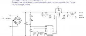
Network switching power supply (Fig. 3) is designed for telephone sets with automatic caller identification or for other devices with a power consumption of 3...5W, powered by a voltage of 5...24V.
The power supply is protected against output short circuit. The instability of the output voltage does not exceed 5% when the supply voltage changes from 150 to 240 V and the load current is within 20... 100% of the nominal value. A controlled pulse generator provides a signal with a frequency of 25...30 kHz based on the VT3 transistor. Chokes L1, L2 and L3 are wound on magnetic cores of type K10x6x3 from pressed permalloy MP140. The inductor windings L1, L2 contain 20 turns of 0.35 mm PETV wire and are each located on its own half of the ring with a gap between the windings of at least 1 mm.
Choke L3 is wound with 0.63 mm PETV wire turn to turn in one layer along the inner perimeter of the ring. Transformer T1 is made on a magnetic core B22 made of M2000NM1 ferrite.
Rice. 3. Diagram of a network switching power supply.
Its windings are wound on a collapsible frame turn to turn with PETV wire and impregnated with glue. The first winding I is wound in several layers, containing 260 turns of 0.12 mm wire. A shielding winding with one terminal is wound with the same wire (shown with a dotted line in Fig. 3), then BF-2 glue is applied and wrapped with one layer of Lakot-kani.
Winding III is wound with 0.56 mm wire. For an output voltage of 5V, it contains 13 turns. Winding II is wound last. It contains 22 turns of wire 0.15...0.18 mm. A non-magnetic gap is provided between the cups.
Pulse modulating cycloconverters
Traditionally, cycloconverters (CC) are understood as thyristor frequency converters with direct coupling, i.e., without an intermediate filter element of direct voltage (capacitor) or direct current (reactor) [2, 3]. The principle of operation of a classic cycloconverter is associated with a single conversion of alternating current electricity of an unstable (usually increased) frequency into alternating current electricity of a constant frequency (for example, 400 or 50 Hz) through cyclic heteropolar rectification of alternating current with amplitude (or phase) modulation of the average rectified voltage.
Compared to a frequency converter (FC) with an intermediate DC reactor link (Lр), the CC is distinguished by higher efficiency, better weight and size parameters (with the same quality of output voltage) and the possibility of common grounding of network neutrals (Fig. 1).
However, a common disadvantage of CCs and inverters with Lp is the poor quality of the input and output current, namely, the low value of the power consumption factor and the high value of the nonlinear distortion (harmonics) coefficient of the output current. The consequence of this is a low overall conversion efficiency (due to large heat losses in the circuits of the primary and secondary networks), large weight and dimensions of the output filters and the primary power supply, and high noise emissions (poor EMC parameters).
In contrast to the indicated traditional (earlier) understanding of the term “converter” as “a reducing agent of the same type, but with changed quality parameters,” this work uses a later and narrower interpretation of this term in power electronics, namely a DC-DC converter to constant (broader: constant or unipolar pulsating voltage to similar, but with different quality parameters).
In the above context of a broad interpretation of the term “converter,” a pulse modulating cycloconverter (PMCC) is understood as a pulse converter with a cyclically repeating law of high-frequency pulse-width modulation of a constant or rectified pulsating supply voltage (with a sinusoidal envelope) followed by reactor demodulation and polarity switching to isolate low-frequency sinusoidal envelope - output current.
To implement these processes, the modulating pulse converters discussed above, as well as the reactor demodulators and output current polarity switches discussed below, are used as part of autonomous inverters and frequency converters.
High voltage constant voltage source
To create a high voltage (30...35 kV at a load current of up to 1 mA) to power an electroeffluvial chandelier (A.L. Chizhevsky’s chandelier), a DC power source is designed based on a specialized microcircuit of the K1182GGZ . The power supply consists of a mains voltage rectifier on a diode bridge VD1, a filter capacitor C1 and a high-voltage half-bridge oscillator on a DA1 chip of the K1182GGZ type. The DA1 chip, together with transformer T1, converts direct rectified mains voltage into high-frequency (30...50 kHz) pulsed voltage. The rectified mains voltage is supplied to the DA1 microcircuit, and the starting circuit R2, C2 starts the microcircuit's self-oscillator. Chains R3, SZ and R4, C4 set the frequency of the generator. Resistors R3 and R4 stabilize the duration of the half-cycles of the generated pulses. The output voltage is increased by winding L4 of the transformer and supplied to a voltage multiplier using diodes VD2 - VD7 and capacitors C7 - C12. The rectified voltage is supplied to the load through limiting resistor R5. Line filter capacitor C1 is designed for an operating voltage of 450 V (K50-29), C2 - of any type for a voltage of 30 V. Capacitors C5, C6 are selected within the range of 0.022...0.22 μF for a voltage of at least 250 V (K71-7, K73 -17). Multiplier capacitors C7 - C12 type KVI-3 for voltage 10 kV. It is possible to replace it with capacitors of types K15-4, K73-4, POV and others with an operating voltage of 10 kV or higher.
Rice. 4. Circuit diagram of a high voltage DC power supply.
High-voltage diodes VD2 - VD7 type KTs106G (KTs105D). Limiting resistor R5 type KEV-1. It can be replaced with three MLT-2 type resistors of 10 MOhm each.
A television line transformer, for example, TVS-110LA, is used as a transformer. The high-voltage winding is left, the rest are removed and new windings are placed in their place. Windings L1, L3 each contain 7 turns of 0.2 mm PEL wire, and winding L2 contains 90 turns of the same wire. It is recommended to include a chain of resistors R5, which limits the short circuit current, in the “negative” wire, which is connected to the chandelier. This wire must have high-voltage insulation.
Types of power supplies
There are two principles for converting electricity in devices: based on an analog transformer and on switching power supplies (UPS).
Transformer power supplies.
The peculiarity of power supplies of this type is the use of a power transformer to change the voltage in the network. The devices reduce the amplitude of the sinusoidal harmonic and direct it to a rectifier consisting of power diodes. Smoothing occurs due to a parallel connected capacitance. The final stabilization of the supply voltage is carried out in a semiconductor circuit with resistors.
Until recently, transformer converters were the only ones of their kind, but had disadvantages:
- heavy weight and large dimensions;
- high cost, often many times higher than the price of other network components.
Pulse power supplies.
The design of the device does not include a step-down transformer. Almost all modern equipment uses switching power supplies as the most compact and efficient ones.
Power factor corrector
The device, called a power factor corrector (Fig. 5), is assembled on the basis of a specialized TOP202YA3 microcircuit (Power Integration) and provides a power factor of at least 0.95 with a load power of 65 W. The corrector brings the shape of the current consumed by the load closer to a sinusoidal one.
Rice. 5. Power factor corrector circuit based on the TOP202YA3 microcircuit.
The maximum input voltage is 265 V. The average frequency of the converter is 100 kHz. The efficiency of the corrector is 0.95.
Switching power supply with microcircuit
The diagram of a power supply with a microcircuit from the same company Power Integration is shown in Fig. 6. The device uses a semiconductor voltage limiter - 1.5KE250A.
The converter provides galvanic isolation of the output voltage from the mains voltage. With the ratings and elements indicated in the diagram, the device allows you to connect a load that consumes 20 W at a voltage of 24 V. The efficiency of the converter approaches 90%. Conversion frequency - 100 Hz. The device is protected from short circuits in the load.
Rice. 6. Circuit diagram of a 24V switching power supply on a microcircuit from Power Integration.
The output power of the converter is determined by the type of microcircuit used, the main characteristics of which are given in Table 1.
Table 1. Characteristics of TOP221Y - TOP227Y series microcircuits.
| Chip type | Рmax, W | Protection current, A | Open transistor resistance, Ohm |
| TOP221Y | 7 | 0,25 | 31,2 |
| T0P222Y | 15 | 0,5 | 15,6 |
| T0P223Y | 30 | 1 | 7,8 |
| T0P224Y | 45 | 1,5 | 5,2 |
| T0P225Y | 60 | 2 | 3,9 |
| T0P226Y | 75 | 2,5 | 3,1 |
| T0P227Y | 90 | 3 | 2,6 |
Introduction
In recent years, a large number of modular secondary power supplies, both foreign and domestic, have appeared on the Russian power electronics market, which are positioned for use in highly reliable systems, such as telecommunications equipment and industrial automation equipment. However, in practice it often turns out that these products do not meet modern reliability requirements, and the level of circuit design solutions is at the turn of the late 80s of the last century. This is largely explained by the specifics of our market: it is often difficult for consumers to understand why products from different companies that seem to have similar electrical characteristics differ in price by 2-4 times. He gets the answer to this question in the first year of operation, when the first statistics on equipment failures appear. In this article we will look at the main circuit solutions and compare their effectiveness in terms of minimizing losses and increasing reliability.