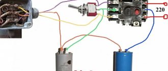
Asynchronous motors are actively used in everyday life and in production. When starting, in some cases there may not be enough torque for them. To solve this problem, a starting circuit with a specially selected capacitor is used. To choose and use it correctly, you need to know why a capacitor is needed in an electric motor and how to correctly determine its characteristics.
Connection diagram for starting and running capacitors Source shenrok.blogspot.com
What is a starting capacitor
When the electric motor is in operating mode, its movement is provided by the windings. However, when at the moment of start you need to start rotating, the usual engine efforts are not enough. Without the use of additional means, it will only begin to tremble slightly.
Typically one of the engine elements is a run capacitor. It accumulates a charge that is capable of exceeding the operating voltage, and then releases it at the right moment. However, its work is not enough to start it. To do this, you need to connect another capacitor in parallel, which is called a starting capacitor.
Selection of a working capacitor Source sdelaysam-svoimirukami.ru
It is launched for a short time, which does not exceed a few seconds. Sometimes this is done by briefly pressing the start button, and sometimes the shutdown is done automatically after the engine begins to pick up speed.
The use of a starting capacitor is especially important in cases where the engine needs to be started under load. In this case, it will be necessary to increase the starting torque during the first seconds of operation.
In some cases, the engine is started with a light load. In this case, a starting capacitor may not be needed. This applies to motors whose power does not exceed 1 kW. Refusal to use it will simplify the scheme and reduce costs. Sometimes the load can be related to design features. In this case, you can take measures to reduce it, which will make it easier to start the engine in the future.
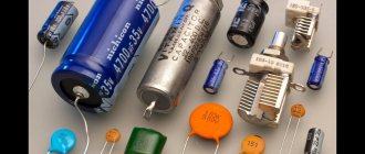
Various starting capacitors Source antemion.ru
Monitor inverter repair. Part I. Capacitors.
Classic LCD monitor power supply.
Diagnostics of any LCD monitor begins with a simple operation, replacing all electrolytic capacitors. It would seem that such banal advice is described on many Internet resources, and there should not be any difficulties in its implementation. But recently, more and more often we have come across monitors that are brought in for repair with a diagnosis that they cannot be repaired, but in fact, when replacing capacitors, 1-2 capacitors were missed, and the replacement of which turned out to be fatal. We will try to present the material from a perspective - minimum theory, maximum practice and with a minimum set of specialized tools
Theory.
Impulse power block.
We will consider common truths, but which for some unknown reason are forgotten by repairmen who take on monitor repair for the first time. This item is intended for those specialists who confidently understand how voltage differs from current, but under certain circumstances slept during lectures on switching power supplies. Most modern power supplies up to 100 watts are designed using a flyback design, including the monitor power supply.
Classic switching power supply for LCD monitor.
Most monitors have exactly this set of capacitors, high-quality monitors have a little more capacitors, and cheap monitors have a little less, but the logic of capacitor distribution is exactly this:
- 80uF*450V – 1 pc.
- 1000uF*25V – 3 pcs.
- 470uF*35V — 3 pcs.
- 47uF*63V — 1 pc.
Capacitors that are always changed during repair/diagnosis are highlighted in bold. Since the switching power supply operates at a high frequency, it means that during proper repairs, capacitors with low ESR, that is, silver or gold, should be installed.
Practice.
Capacitors
If during a one-time repair the cost of capacitors has practically no effect on the cost price, then during a flow, the use of capacitors with low ESR is quite expensive and has little justification. A classic 105C capacitor from a trusted manufacturer also does its job well and has a service life of 2 to 5 years. In addition, the gold and silver stripe on the capacitor indicates that the capacitor MAYBE has a low ESR, due to a lot of fakes on the market. Opening the monitor without a set of main capacitors (1000uF*25V - 3 pcs. 470uF*35V - 3 pcs. 47uF*63V - 1 pc.) does not make any sense at all.
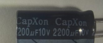
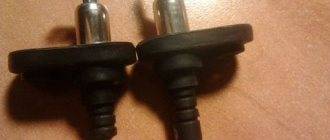
Start capacitor
Start capacitor
It is this capacitor that is the reason for all the “impossible” repairs for beginners. The reason is simple: the capacitor never swells, which means it visually appears to be in good working order. On the other hand, the capacitance of this capacitor determines the total capacitance of the output capacitors; with a starting capacitor capacity of 47 μF, the total capacitance of the output capacitors should not exceed 2500 μF. This is a practical and very approximate formula; the use of chokes in secondary circuits can significantly change the total capacitance of the output capacitors.
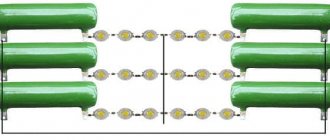
Power supply with two starting capacitors
It should be noted that there is a certain category of PWM in which two starting capacitors are used; therefore, both capacitors are changed.
+12V circuit
+12V circuit
The first capacitor after the rectifier diode must be with low ESR; if it is impossible to set Low ESR, a capacitor with a higher operating voltage is installed. Whatever the capacitor is, a 1000 µF * 25V (1000 µF * 35V) capacitor is installed here; after it, a choke is usually installed and again a capacitor, but this time at 470 µF * 35V. After the +12V rectifier, a fuse or jumper is usually installed, which is used to diagnose the +12V power supply. Two 470uF*35V capacitors are installed behind the power supply in close proximity to the inverter switches; formally, these capacitors are installed in the inverter. There is an important note here, if the first capacitor is 1000 µF, then the remaining capacitors are set to 470 µF, this is not saving - greater filtering cannot be achieved here, RF interference creeps in from the side of the HF transformer through the rectifier, but RF interference also comes from the inverter side, so these capacitors are between two fires, so these capacitors are between two fires, which is why it is not the capacitance that is so important here, but the operating voltage. If you install all 1000uF capacitors, then there is a chance that the starting capacitor will not be able to start the power supply because its capacity is not enough to charge the output capacitors. Considering that the voltage then goes to drive the HF transformers of the inverter, there are no strict requirements for the +12V voltage, and in this circuit you can easily have a voltage of up to +15.6V instead of the required +12V
+5V circuit
+5V circuit
The first capacitor after the rectifier diode must be with low ESR; if it is impossible to set Low ESR, a capacitor with a higher operating voltage is installed. Whatever the capacitor is, a 1000 µF * 25V capacitor is installed here. After it, a choke and a capacitor are usually installed, usually 47 μF * 10V, instead of which we always install a capacitor 1000 μF * 16V (1000 μF * 25V). The feedback circuit is started precisely from the +5V circuits. The +5V themselves do not enter the power supply circuit, but go directly to the scalar.
Rectifier circuit.
Rectifier circuit
The most expensive capacitor in the power supply and for this reason is very rarely changed. In most cases, the malfunction is determined by visual inspection; if capacity is lost, the power supply does not produce full power, since it is this capacitor that determines the output power of the flyback power supply. Universal replacement for 100 µF*450V (80 µF*450V).
Replacing capacitors.
An inherently simple procedure, sometimes it ends sadly for beginners; after watching enough videos on YouTube, they replace faulty ones with known good ones and... the monitor does not start. This is due to the use of active flux; beginners can easily use it to replace capacitors.
An example of a board after soldering with active flux, the board did not start, but the consequences of even a short-term start are impressive.
On the picture:
- The textolite around the leg of the HF transformer burned out and became conductive. This leg was not soldered; a drop of flux got there through negligence.
- Under the influence of surface RF currents, the capacitor became charred.
- The flux, of course, evaporated, but the resistance of the light areas of the PCB became 4-6 MΩ instead of the required more than 100 MΩ.
An example of a board after soldering with active flux, the board did not start, the PCB burned out under the capacitor of the high-voltage rectifier.
What is a capacitor
This part contains two metal plates, between which there is a dielectric layer. When voltage is applied to the plates, a charge accumulates on them. The electrical is inside the capacitor. The stronger the charge is on the plates, the stronger it is.
If you disconnect the voltage from the plates, the capacitor begins to release charge. If alternating current is used, the polarity of the voltage will periodically change. In this case, the plates will alternately have a positive and a negative charge.
The capacitance of a capacitor is its most important characteristic. It characterizes how much energy he is able to pass through himself. It is measured in farads. Since we are talking about a very large quantity, prefixes are usually used to indicate how small a part is used. The most commonly used is microfarads (this unit is equal to 0.000001 farads).
Motor connection procedure Source kabel-house.ru
There is a voltage rating for each capacitor. With it, this part is able to work for a long time and reliably. The maximum operating time value, which is expressed in the number of hours, must be indicated.
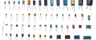
There are different types of capacitors:
- Polar are designed for use in DC circuits. An important feature is the need to connect in accordance with the polarity indicated on them. They are usually small in size and have a relatively large capacity.
- Non-polar ones can be connected regardless of polarity. They are used in alternating current circuits. They are larger in size than the polar ones.
- Electrolytic. They use sheets of foil as plates, and the dielectric is a thin layer of oxide.
Electrolytic ones are best suited for use as a starting capacitor. They are often used with an AC frequency of 50 Hz and a voltage of 220-600 volts. Capacitors can have a fairly high capacity; it can be hundreds of thousands of microfarads.
These parts are highly vulnerable to overheating. If the thermal regime is violated, they quickly fail. Non-polar capacitors do not have this disadvantage, but are several times more expensive.
Single-phase asynchronous motor Source asutpp.ru
When connected in parallel, the containers add up. In the event that it is not enough, you can connect an additional part in parallel to increase it. In this situation there is no need to reassemble the trigger circuit.
Other types of capacitors are also used. For example, these can be vacuum, liquid, gas and others. However, they are not used as starting capacitors.
Sometimes the capacitor that is included in the design fails to start. In this case, it is recommended to remove it and replace it with one that has a larger capacity. For low-power motors, it is permissible for one capacitor to perform the functions of working and starting.
The use of polar capacitors in alternating voltage conditions is possible when the connection is made through a diode. Now the polarity of the contacts will not change. However, if the diode is faulty, the part will fail.
Construction of an asynchronous motor Source elektrikexpert.ru
Advantages and disadvantages
Advantages of electrolytic capacitors:
- Large capacity;
- Compactness.
Flaws:
- Over time, the electrolyte dries out and capacity is lost;
- Works only at low frequencies;
- Operating limitations and risk of swelling/explosion.
Let's take a closer look at the advantages and disadvantages of electrolytes.
Large capacity
Electrolytic capacitors have a large capacity, and this is their distinctive and most important feature among other capacitors.
Capacitance is indicated in microfarads (μF), since electrolytes with lower values are not produced.
They are usually produced from several microfarads to several f (1,000,000 microfarads).
Compactness
Thanks to chemical sources, high-capacity capacitors are much more compact than if they were made from ceramic or film.
The capacitance of a capacitor can be increased only due to its plates, dielectric and geometry. Therefore, electrolytes lead in terms of capacity/dimensions ratio.
Ionistors
A type of electrolytic capacitors are ionistors. They have a larger capacity (for example, 3000 F), and operate primarily as a backup or self-contained low-voltage power supply for the circuit. And also supports the circuit in sleep mode without another source.
Electrolyte drying out
The main problem with such capacitors is drying out of the electrolyte. Typically, this problem manifests itself due to the fact that the equipment is not used for a long time or the operating conditions are violated (overheating of the case). Because of this, the electrolyte begins to dry out, resulting in a loss of capacity.
It is possible to restore the capacitor's capacity by diluting the dried electrolyte with distilled water (like a battery), but this is not profitable. The best and most reliable way is to replace the old one with a new one, similar in parameters.
Low Frequency Operation
This is more of a feature than a drawback. Large capacitances mean high reactance for high frequencies.
Therefore, such capacitors are used in low-frequency circuits. For example, in power supplies as filters and ripple smoothing.
When a capacitor swells and explodes
Since capacitors of this type are chemical sources, the polarity of the connection must be observed.
Capacitors, like batteries, can swell and explode. Sometimes this happens due to improper activation or overheating.
If you connect the minus of the source to the plus of the capacitor and the plus of the source to the minus of the capacitor, then boiling of the electrolyte will immediately begin. This effect occurs due to a reverse chemical reaction. The capacitor may explode.
In old capacitors of the K-50 type, the body was monolithic, and it exploded loudly and quite destructively.
In modern electrolytes, there is a small cut on the body, which, if the electrolyte boils, allows hot steam to escape.
Sometimes they are simply blown in without breaking the seal, and there are also cases when the capacitor completely loses its seal.
However, the notch on the case has greatly reduced explosions, so capacitors are now more likely to swell rather than explode.
On the housings of modern capacitors, a vertical line indicates the negative contact.
Carefully set and record the previous position, because many manufacturers put their own designations.
For example, among radio amateurs, negative contacts are usually drawn in the form of a square.
On the contrary, printed circuit board manufacturers draw square contact pads for the plus of the capacitor. And then, not everyone does this.
Since there is such confusion among both radio amateurs and manufacturers, always pay attention to this. where the positive contact is indicated. And write down the previous position of the part, otherwise it is fraught with an explosion.
Use of asynchronous motors
Three-phase and single-phase asynchronous motors are actively used in various sectors of the economy. There are several reasons for this:
- Simplicity of design.
- Reliability and durability during use.
- In order to start the engine, there is no need to use expensive and scarce devices.
- The motor does not require too frequent maintenance.
By appearance, you can easily distinguish three-phase motors from single-phase ones. The former always have 6 terminals, while the latter have two or four.
For three-phase motors, the windings are connected in two ways: star or delta. They assume the use of a voltage of 380 volts. However, it is rarely used in everyday life. To use such a motor, you need to know how to connect it correctly.
This is done using a phase-shifting capacitor. This will allow the use of three-phase motors when connected to a single-phase network. In this case, the motor power will be equal to 50% -60% of the nominal.
Checking the starting capacitor Source antemion.ru
Optimal operation of a three-phase motor is ensured by using a variable capacitance. To do this, at the first stage, working and starting capacitors are used, and at the second, only the first of them.
Asynchronous single-phase motors are often used in everyday life. Additional winding is usually required to start.
When choosing the capacitance of a capacitor, it is necessary to take into account how the magnitude of the starting torque depends on it. As this characteristic increases, the force increases. At a certain value it becomes maximum. After a further increase, the starting torque will begin to fall.
Calculation of capacitor parameters Source uk-energotekhservis.rf
Specifics of circuits with capacitors
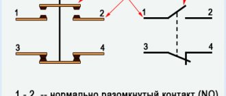
When selecting the types of switching on of electric machines using starting and working two-terminal circuits for a 220 volt network, the following are distinguished:
- inclusion in the “triangle”;
- star connection.
For your information. What are the differences between starting and working two-terminal networks? “Starting” are elements that are used only for starting, and “working” are those that are constantly used in operation.
Connection diagrams for a 380 V line
There is no need to use capacitive elements when connecting a 3-phase motor to a 380 volt network.
Schemes for connecting to a single-phase network
When installing a single-phase motor in a single-phase line, it is started using an additional winding. Such a motor has three outputs:
- from the working coil;
- from additional;
- common output for both windings.
What characteristics are taken into account when choosing
The installation of the capacitor must be done strictly according to the relevant regulations. Its selection is made based on the following information:
- Motor type (single-phase or three-phase) and winding connection method (delta or star).
- The power supply network used. In everyday life you can most often find 220 V. A supply voltage of 380 V is also used, provided that the network is three-phase. The latter option is often used in industrial settings.
- Engine power.
- The power factor in most cases is 0.9.
- Electric motor efficiency.
This data can be obtained from the operating instructions for the electric motor. Electrical grid data must be available from other sources. For calculations, you can use an online calculator or do the calculations yourself.
There are additional parameters that also need to be taken into account:
- Permissible deviation from the calculated value.
- The temperature range in which the part should operate. For some varieties, going beyond it may cause damage.
- The resistance level of the dielectric used.
- Loss tangent.
These parameters are not critical. Therefore, they are often forgotten. However, the more carefully the starting capacitor is selected, the more reliable and durable the operation of the motor will be.
Additionally, you need to pay attention to the size and location of the part. Typically, as the capacity increases, the dimensions of the part increase. Sometimes there may be a choice between brands from different manufacturers. You need to choose those that produce higher quality and more reliable parts.
Starting capacitor SVV-60 Source aliradar.com
Subscribe to the newsletter
Three-phase motors are designed for an operating voltage of 380 V. But such voltage is not always available in everyday life. Therefore, a problem arises: how to connect an electric motor through a capacitor to a household network? The most acceptable and widely available method is to use a phase-shifting capacitor. In this mode, 50–60% of the nominal power can be achieved. Note that not all asynchronous motors will work equally well when connected to a single-phase network. The engines most adapted to these conditions are those with a squirrel-cage rotor made in the form of a double cage.
Optimal operation of the electric motor is achieved only if the capacitance of the capacitor changes as the rotation speed increases. In practice it is very difficult to implement this requirement. In this regard, two-stage motor control is adopted. Starting is carried out using two capacitors (starting - Sp and working - Wed). Then, when the desired rotation speed is reached, the starter must be turned off. Its main function is to increase the starting torque.
The calculation of a capacitor for an electric motor can be done in this way. The calculation formula looks like: Ср = К*(In/U). The following notations are used here:
current strength (nominal) - In (A);
voltage (nominal) - U (V);
K is a dimensionless coefficient.
The value of K is determined by how the engine is turned on. K = 2800 when the engine is turned on in a star configuration. If it is switched on according to the “triangle” circuit, then the value K = 4800 (Fig. 1).
It is recommended to choose paper capacitors for starting an electric motor, in particular:
- paper, sealed, in a metal case, marked KBG-MN (Fig. 2);
- paper, heat-resistant, symbol BHT;
- metal-paper, frequency, MBGCH.
If it is necessary to change the direction of rotation of the motor, it is enough to swap the wires connected to the terminals of the capacitor. It is better to start an electric motor using a capacitor using a delta circuit. In this case, you can achieve maximum output power (up to 70%).
As an example, consider the AO2 engine. Its rated power is 2.2 kW, rotation speed is 1420 rpm. To start it in idle mode (or when there is a load), you will need 2 capacitors: the first with a capacity of 230 μF (working) and the second with a capacity of 150 μF (starting).
To ensure reliable operation of the electric motor, starting capacitors are used.
The greatest load on the electric motor occurs at the moment of its start. It is in this situation that the starting capacitor begins to work. We also note that in many situations the start-up is carried out under load. In this case, the load on the windings and other components is very high. What design allows you to reduce the load?
All capacitors, including starting capacitors, have the following features:
- as a dielectric . In this case, an oxide film is often used, which is applied to one of the electrodes.
- Large capacity with small overall dimensions is a feature of polar storage devices.
- Non-polar ones are more expensive and larger, but they can be used without regard to polarity in the circuit.
This design is a combination of 2 conductors that are separated by a dielectric. The use of modern materials can significantly increase the capacity indicator and reduce its overall dimensions, as well as increase its reliability. Many with impressive performance indicators have dimensions of no more than 50 millimeters.
How to choose a starting capacitor
For it to work most effectively, you need to choose the right container. To calculate it, various formulas are used, depending on the method of connecting the windings. The calculations are performed as follows:
- It is necessary to determine the operating current and voltage of the motor. When carrying out calculations, the designations I and U are used for them. The current value is taken from the operating instructions for the motor, and as U we take the one provided by the supply voltage.
- Capacity is determined by the formula C = (K x I) / U.
If the windings are connected in a triangle, K = 4800 is used, and when connected in a star, K = 2800 should be used. The result of the calculation is the capacitance expressed in microfarads.
Connecting a single-phase asynchronous motor Source sibay-rb.ru
When making calculations, the rated current must be taken into account. We are talking about the maximum permissible operating current under conditions when the engine is operating in normal mode. In practice, its value depends on the available load. If it is not there, then the value will be minimal.
This value is called no-load current. It is actually compensation for losses associated with energy losses in windings, dielectrics, friction and other similar reasons.
Connecting a three-phase motor to a single-phase network Source stroysvoy-dom.ru
If you gradually increase the load, the current will increase. Then it will reach the nominal value. With a subsequent increase, the current will continue to increase, but the speed will begin to fall. Prolonged stay in this mode will lead to increased wear of the equipment and possible breakdown.
You can determine the rated current not only from the operating instructions, but also measure it yourself. In the latter case, its value will be determined more accurately. This measurement can be done as follows:
- Disconnect the capacitors.
- Start the engine in operating mode.
- Using a current clamp, the current strength is determined.
Based on the obtained value, the required capacity is determined. Then they purchase the required part and install it. In this case, deviation from the calculated value is allowed by no more than 15%.
Schemes for connecting a three-phase motor to a single-phase network Source orenburgelectro.ru
When connecting a single-phase motor, the capacity of the working capacitor is determined as follows. You need to take 7 microfarads for every 100 watts of rated power. For starting, the capacity is chosen 2-3 times larger. Single-phase asynchronous motors are often used in home appliances.
For this purpose, capacitors of the following designs are usually chosen:
- metal-paper, high-frequency, which are designated MBGCH;
- heat-resistant paper type belonging to the BHT variety;
- paper in a sealed metal case - KBG-MN.
If the motor needs to rotate in the reverse direction, the connection to the capacitor will need to be changed. To do this, it will be enough to simply swap the terminals. If we are talking about replacing an existing part, then it is most convenient to choose it with the same characteristics as before.
As a working one, you must use a non-polar capacitor designed for use with alternating current. This is due to the fact that the polarity will constantly change during operation. However, it is permissible to use a polar one as a starter. In order to prevent the voltage sign from changing, it is necessary to connect this part via a diode.
Using starting and running capacitors for connection Source uk-parkovaya.ru
Capacitorless starting of three-phase electric motors from a single-phase network
As is known, to start a three-phase electric motor (EM) with a squirrel-cage rotor from a single-phase network, a capacitor is most often used as a phase-shifting element. In this case, the capacity of the starting capacitor should be several times greater than the capacity of the working capacitor. For electric motors most often used in households (0.5 - 3 kW), the cost of starting capacitors is comparable to the cost of an electric motor. Therefore, it is desirable to avoid the use of expensive starting capacitors that only work for a short time. At the same time, the use of working, constantly switched on phase-shifting capacitors can be considered appropriate, since they allow the engine to be loaded at 75.
85% of its power when switched on 3-phase (without capacitors its power is reduced by about 50%). A torque quite sufficient to start the indicated electric motors from a single-phase 220 V/50 Hz network can be obtained by shifting the currents in phase in the phase windings of the electric motor, using for this purpose bidirectional electronic switches, which are turned on at a certain time.
Based on this, to launch 3-phase electric motors from a single-phase network, the author developed and debugged two simple circuits. Both schemes were tested on an electric motor with a power of 0.5. 2.2 kW and showed very good results (start-up time is not much longer than in three-phase mode). The circuits use triacs controlled by pulses of different polarities and a symmetrical dinistor, which generates control signals during each half-cycle of the supply voltage.
The first circuit (Fig. 1) is intended for starting electric motors with a rated rotation speed equal to or less than 1500 rpm, the windings of which are connected in a triangle. The basis for this scheme was taken from scheme [1], which was simplified to the limit. In this circuit, an electronic switch (triac VS1) ensures a current shift in winding “C” by a certain angle (50. 70°), which provides sufficient torque.
The phase shifting device is an RC circuit. By changing resistance R2, a voltage is obtained on capacitor C that is shifted relative to the supply voltage by a certain angle. A symmetrical dinistor VS2 is used as a key element in the circuit. At the moment when the voltage on the capacitor reaches the switching voltage of the dinistor, it will connect the charged capacitor to the control terminal of the triac VS1 and turn on this bidirectional power switch.
The second circuit (Fig. 2) is intended for starting electric motors with a rated rotation speed of 3000 rpm, as well as for electric motors operating mechanisms with a high resistance moment during starting. In these cases, a significantly larger starting torque is required. Therefore, an “open star” connection scheme for the EM windings was used ([2], Fig. 14, c), which provides maximum starting torque. In the indicated circuit, the phase-shifting capacitors are replaced by two electronic switches. One switch is connected in series with the winding of phase “A” and creates an “inductive” (lagging) in it.
current shift, the second is connected in parallel to the winding of phase “B” and creates a “capacitive” (advanced) current shift in it. Here it is taken into account that the EM windings themselves are displaced in space by 120 electrical degrees relative to each other.
The adjustment consists of selecting the optimal shift angle of the currents in the phase windings, at which the electric motor is reliably started. This can be done without the use of special devices. It is performed as follows.
Voltage is supplied to the electric motor by a push-type “manual” starter PNVS-10, through the middle pole of which a phase-shifting chain is connected. The middle pole contacts are closed only when the “Start” button is pressed.
By pressing the “Start” button, by rotating the trimmer resistance R2, the required starting torque is selected. This is what you do when setting up the circuit shown in Fig. 2.
When setting up the circuit in Fig. 1, due to the passage of large starting currents, the electric motor hums and vibrates strongly for some time (before turning around). In this case, it is better to change the value of R2 in steps when the voltage is removed, and then, by briefly applying voltage, check how the EM starts. If the voltage shift angle is far from optimal, then the ED hums and vibrates very strongly. As it approaches the optimal angle, the engine “tries” to rotate in one direction or another, and at the optimal angle it starts quite well.
The author debugged the circuit shown in Fig. 1 on an electric motor of 0.75 kW 1500 rpm and 2.2 kW 1500 rpm, and the circuit shown in Fig. 2 on an electric motor 2.2 kW 3000 rpm .
At the same time, it has been experimentally established that it is possible to select the values of R and C of the phase-shifting chain corresponding to the optimal angle in advance. To do this, you need to connect a 60 W incandescent lamp in series with a key (triac) and plug them into the network
220 V. By changing the value of R, you need to set the voltage on the lamp to 1 70 V (for the circuit in Fig. 1) and 1 00 V (for the circuit in Fig. 2). These voltages were measured by a pointer device of the magnetoelectric system, although the voltage shape across the load is not sinusoidal.
It should be noted that optimal current shift angles can be achieved with various combinations of values of R and C of the phase-shifting chain, i.e. By changing the capacitance value of the capacitor, you will have to select the corresponding resistance value.
Experiments were carried out with triacs TS-2-10 and TS-2-25 without radiators. They worked very well in this scheme. You can also use other triacs with bipolar control for the corresponding operating currents and voltage class not lower than 7. When using imported triacs in a plastic case, they should be installed on radiators.
The symmetrical DB3 dinistor can be replaced with the domestic KR1125. It has a slightly lower switching voltage. Perhaps this is better, but this dinistor is very difficult to find on sale.
Capacitors C are any non-polar, designed for an operating voltage of at least 50 V (preferably 100 V). You can also use two polar capacitors connected in back-to-back series (in the circuit in Fig. 2, their nominal value should be 3.3 μF each).
The appearance of the electric drive of the grass chopper with the described startup circuit and 2.2 kW 3000 rpm motor is shown in photo 1.
Installation check
Once a suitable starting capacitor has been selected, it must be tested. To do this you need to do the following:
- First you need to turn off the power from the electric motor.
- It is necessary to de-energize the capacitor, since a residual charge could remain on it. To do this, you need to short-circuit its windings.
- Now you need to remove one of the terminals and connect a device to measure capacitance.
- The probes are connected to the terminals of the capacitor. After this, the measuring device will show the exact capacitance value.
When using a multimeter, you must first set the main switch to capacitance measurement mode.
When carrying out calculations, you can use a simplified version. It is known that the starting current can exceed the rated current by 3-8 times. Therefore, you can simply use a capacity 2-3 times larger than that of the working capacitor. If the starting capacity is not enough, you can simply take a more suitable capacitor.
Detailed characteristics of the starting capacitor Source electrikexpert.ru
Connecting an electric motor with your own hands
How to choose a capacitor for a single-phase motor is already clear. The selection of capacitors for a three-phase motor is considered. How to practically mount a circuit to start an engine, what is necessary for this?
The circuit consists of the following components:
- engine (up to 3 kW);
- capacitors: starting and running, which differ in capacity;
- 220 V PVS start button.
Why do you need a start button? For short-term connection of an electrolytic two-terminal network and starting the motor rotation. The circuit is assembled according to the diagram in the picture below. All connections are made using bolted clamps. Bare sections of wires are subject to mandatory insulation.
The use of starting and operating capacitors makes it possible to start motors in any circuit. The capacity of the two-terminal circuits should be sufficient to start rotation and stable operation under load. It is preferable to use new parts.
Difference between start and run capacitors
To better understand why a starting capacitor is needed and what the features of their application are, you need to know about their differences. The main ones are the following:
- They have different installation locations. The worker is part of the circuit of working motor windings. The starter is part of the motor starting circuit.
- Capacitors differ in exactly when they are supposed to work. The starter is connected to the circuit during the first few seconds after starting. Then it is turned off in manual or automatic mode. The worker performs his functions during the entire time the engine is running.
- Each of them has its own functions. The starting one provides a phase shift between the windings to provide the main force when initially starting the motor. The worker ensures the rotation of the phases necessary for normal operation of the electric motor.
- Each capacitor type has different operating voltage requirements. The starting unit must be designed for one that exceeds the supply by 2-3 times. The worker must be designed for one that is 1.15 times greater than the incoming one.
In both cases, capacitors of the MBGO and MBGCh types are most often used.
Purpose and benefits
Capacitors of the type in question are used in the connection system of an asynchronous motor. In this case, it works only at the time of start-up, until the operating speed is reached.
The presence of such an element in the system determines the following:
- The starting capacitance makes it possible to bring the state of the electric field closer to circular.
- is being carried out .
- increases and engine performance improves significantly.
Without the presence of this element in the system, the service life of the engine is significantly reduced. This is due to the fact that a complex start-up leads to certain difficulties.
The advantages of a network that has a similar element are as follows:
- Easier engine starting.
- service life is significantly longer.
The starting capacitor operates for several seconds when the engine starts.
How does the load size affect the choice of capacitors?
If the part is selected in accordance with the calculations given here, then it will fit well under a uniform load. An example of such a situation is the operation of a fan.
If the load changes, then in this case you can use the following trick. For example, you can consider a circular saw, which is used to cut boards and logs. In the first case, it is obvious that the load is less, and in the second - more.
For example, if calculations were made based on the rated current and a capacitance equal to 10 microfarads was obtained, then you need to use such a working capacitor when sawing boards. It will most likely not be enough to work with logs. In this case, when performing work, two such parts are connected in parallel.
If this is not done, the engine will lose power. As a result, it will begin to overheat and to work on it you will need to take breaks to allow the motor to cool down.
To start the engine you need to connect a starting capacitor Source chipmaker.ru
Which type to use
The requirements for capacitors for starting electric motors are simple:
- the capacity is sufficient to start the engine;
- the rated voltage is selected 10-15% higher than the connected one;
- The two-terminal network must work with the applied type of current.
There are small nuances for electric machines that differ in operating principles.
For operation with a three-phase electric motor
In this case, the part carries out a phase shift in the winding of an asynchronous machine, and its capacitance must be high. Creation of a starting torque and further operation under load require a more precise selection of this element characteristic.
Switching on with a single-phase electric motor
Starting capacitors are used here to connect an additional winding. It is designed to start the motor and can be turned on either permanently, through a two-terminal network, or briefly without it.
Part selection features
The selected starting capacitors correspond to the applied voltage. The size of their capacity should not allow the engine to overheat during operation and should be easy to start when turned on. There are no particular difficulties with the selection of elements.
The most common models in Russia
Most often you can find the following brands on sale:
- Capacitors of the SVV-60 brand with a metallized polypropylene version. They have a relatively high price.
- HTC film brands have a fairly high level of quality, but cost a little less than SVV-60.
- E92 are a budget option for starting capacitors. They have a relatively low price, but are inferior in quality and reliability to the previous two options.
There are also a number of other models, but they are less common.
Procedure for connecting capacitors Source uk-parkovaya.ru
Star connection diagram
If there are 6 terminals on the electric motor terminal block, you should ring them separately and determine which terminals are connected to each other. In the motor passport you need to find the purpose of the pins. After this, the circuit is reconnected, forming the usual “triangle”.
For this purpose, the jumpers are removed and the contacts are assigned symbols from A to F. Next, the contacts are connected in series: A and D, B and E, C and F.
Now contacts D, E and F will become the neutral, working and phase wires, respectively. The capacitor is connected to them in exactly the same way as in the previous case.
When you turn it on for the first time, you need to carefully ensure that the windings do not overheat. In this case, you should immediately turn off the device and determine the cause of overheating.
Tips for use
Determining the required characteristics and choosing a model usually requires considerable effort. In this regard, it makes sense to take into account a few tips:
- It is mandatory to use a starting capacitor when working with high-power motors or in cases where it is necessary to start rotation of the shaft with a load.
- Motors smaller than 1 kW can usually be operated without the use of a starting capacitor. Such motors are often used in household appliances.
When connecting the starting circuit, you must carefully follow all the necessary rules. An error can lead to a breakdown or emergency.
Announcements on NN.RU – Construction
Milan kitchen table new with free delivery to your doorstep in the city of Nizhny Novgorod Dzerzhinsk. Size: 1154*752*756 mm frame: legs. Price: 4,500 rub.
OPGS in bags and in bulk! Seven days a week! Delivery throughout the city and region! Any form of payment! Price: 1,350 rub.
Set of kitchen corner table stools new free delivery within the city of Nizhny Novgorod Dastorg factory offers - kitchen corners with. Price: 8,050 rub.
I will deliver a new ash orchid set for free around the city of Nizhny Novgorod, Dzerzhinsk. There are other colors and models from RUB 5,000 on sale. Price: 7,500 rub.
There is a real construction boom in Nizhny Novgorod. In every district of the city, new houses are appearing that will be rented out in the coming years.
Connection methods
In the most common case, the first capacitor is connected to the gap in one of the windings of an asynchronous electric motor, which is also often called “auxiliary”. The other is connected directly to the electrical network, and the third remains unused. This type of circuit is called “star”. There is also a triangle connection. It varies in connection method and complexity.
The second capacitive element, unlike the working one, is connected in parallel to the latter through a button or centrifugal switch. In the first case, control is carried out by a person, and in the second - by the drive itself. Both of these switches briefly close this circuit when the electric motor starts, and after it reaches operating mode, they open it.
Differences between them
They lie in their purpose, capacity, method of connection, as well as operating conditions. The first difference is that the run (first) capacitor serves to shift the phases . As a result, a rotating magnetic field appears between the windings, which is necessary to drive the motor, which is without mechanical load. Such an electric motor is used, for example, in a grinding machine.
Starting (second) provides an increase in the starting torque of the motor , which is under mechanical load, due to which it more easily reaches the desired mode. The resources of one worker may not be enough, which is why the engine rotor simply does not start rotating. The use is justified in conjunction with machines, lifting mechanisms, pumps and similar heavy equipment. It can also be used with a more powerful three-phase motor if there is not enough work force to start it reliably.
The capacity of both capacitors will also be different. It is directly proportional to the power of the electric motor and inversely to the network voltage. Depending on the winding connection diagram, a correction factor is introduced. The starting capacity can be twice that of the working one.