Fluorescent lamps, despite the widespread use of LED lighting, still remain one of the most common types of lamps in homes, garages and industrial premises.
When such a lamp stops burning, the first step is to blame the lamp itself or the starter. And if they are not to blame, how to check another equally important element: the accelerator?
What is a throttle, appearance and device
A choke is a type of inductor; it is a special copper wire wound around a core. But not everything is so simple, they also come without a core, called frameless or air. Outwardly, some look like a transformer. The difference is that the inductor has only one winding, while the transformer has two or more. If there are only two outputs, then this is definitely not a transformer.
Coreless chokes are wire wound in a spiral. We’ve figured out what a choke looks like in electrical engineering, now let’s talk about its design.
What is a choke: it is copper wire wound in a spiral with or without a core
As has already been said, the inductor may or may not have a core. The core can be made of a conductive material - metal, or maybe magnetic. The presence or absence of a core, as well as its type (not only material, but also shape) affect the parameters of the inductor.
Elements without cores are used to cut off high frequencies, while elements with a core are often used for energy storage. There is one more point: if you compare chokes with the same parameters with and without a core, then those that have one are much smaller in size. The better the conductivity of the core, the less wire there is and the smaller the element has dimensions.
Schematic representation of a choke with and without a magnetic core
A few words about the wire that is used to wind the inductor. This is a special insulated wire. Insulation is a thin layer of dielectric varnish, it is invisible, but insulates well. So, when winding a coil yourself, do not use regular wire, only special wire coated with insulation.
The choke in the diagram is indicated by a graphical representation of a half-wave. If it has a magnetic core, a dash is added. If any special metal is required, this is also indicated next to the schematic illustration. The wire diameter (L1) may also be indicated.
↑ Attempt number one, with whistle and technical break
For a start, of course, it’s not bad, and the solution as a whole is workable, but for EL 34 I need a good 100 anode milliamps (not counting 15 mA for the second grid), and they turned out somehow with difficulty, I’m already silent about the interference from the thyristor on standing nearby on a shelf, and a randomly turned on radio. But when testing the circuit, a new problem emerged: as soon as the 34 warmed up, it suddenly became excited, and the peacefully singing receiver suddenly whistled and wheezed like a robber nightingale with a cold. The anode current doubled, and the voltage actually dropped under such a load.
I run to turn everything off and think: what kind of mess is there in my household? Well, yes, the anode does not have enough power, which in this case is just good. And what’s very good is that my EL escaped with a slight fright, unlike me. Why am I so happy? But because there are a lot of wires and a lot of parasitic installation capacitances.
Since changing my lamp is temporarily “out of the question,” I, by a willful decision, short-circuited the 1st grid through a capacitor to the ground. The excitement probably took offense at me, but immediately disappeared.
Of course, it would be possible to make a high-voltage anode power supply using bipolar or field-effect transistors, but it is also prone to self-excitation, burns out if shorted, and I didn’t have 250 Volt zener diodes in my bins.
After some thought, I decided to use LATR to install the anode, but the trouble is that I still haven’t bought it.
I didn’t like the price of 170 evergreens, and the sizes were somehow too large. Plus galvanic connection to the network. Here I again had a long-term technical break...
In the end, everything turned out differently, and much better. Once I successfully bought an ancient transformer with a bunch of taps on the secondary. It honestly once powered the TV, but now, although with the original switch, it was left not only homeless, but also completely without a housing. And here he is, in person.
Properties, purpose and functions
Now let's look at what a throttle is from an electrical point of view. In short, this is an element that smoothes the current in the circuit, which is clearly visible in the graph. If we apply alternating current to it, we will see that the voltage on the coil increases gradually, with some delay. After the voltage is removed, current continues to flow in the circuit for some time. This happens because the coil's field continues to "push" electrons thanks to the stored energy. That is, the current in the inductor cannot appear and disappear instantly.
The current through the inductor increases smoothly and decreases just as smoothly. Looking at these graphs, it becomes clear that the inductor is an element that smoothes the current
This property is used when it is necessary to limit the current, but there are heating restrictions (it is advisable to avoid it). That is, the inductor is used as an inductive reactance that delays or smoothes out current surges. Like a resistor, an inductor has a certain resistance, which causes a voltage drop and limits the current. It just heats up a lot less. Therefore, it is often used as an inductive load.
The inductor has two properties that are also used in circuits.
- since it is a subtype of inductor, it can store charge;
- cuts off current at a certain frequency (the delayed frequency depends on the parameters of the coil).
In some devices (fluorescent lamps), a choke is installed specifically to accumulate charge. In all kinds of filters it is used to suppress unwanted frequencies.
How to measure capacitance and inductance?
The most common methods for measuring resistance, capacitance and inductance are the indirect measurement method (using a voltmeter and ammeter), the resonant method and the bridge method. Measuring the resistance of a resistor by the indirect method can take place on direct and alternating current....
Interesting materials:
How to block a person on VK so that he does not see? How to block another person's phone number? How to block a transfer from a Sberbank person? How to block transfers from a person to Sberbank online? How to block transfers from a person in Sberbank? How can I pick up an item from Wildberry for another person? How to forget a person and not think about him? How does air pollution affect human life? How to close Direct from one person? How to close messages on VK from one person?
Types and examples of use
In order to more accurately understand what a choke is, let's talk about the specific application of this element in circuits. It can be seen in almost any scheme. They are installed if it is necessary to decouple (make independent of each other) sections operating at different frequencies. They smooth out sharp current surges (increases and drops) and are used to suppress noise. In some circuits they work as starting circuits, helping to increase the voltage at the moment of start. Depending on the purpose, they are divided into the following types:
- Smoothing. Due to inductance, they prevent a sharp increase or decrease in current.
- Filtering. Specially selected parameters cut off (suppress) surges at certain frequencies (or in the entire range). They are also placed at the input of static capacitors.
- Network. Installed in devices powered by a single-phase network. Serve to protect equipment from overvoltage.
- Motor. They are placed at the input of electric drives to smooth out starting currents.
Almost every circuit has this element.
How to test a throttle with a multimeter
We have figured out what a throttle is and what it is used for, now it’s also worth learning how to determine its performance. If the multimeter can measure inductance, everything is easy. We're just taking a measurement. If the throttle parameters are unknown to us, we set the largest measurement limit. Usually it's a few hundred Henrys. On the jackal they are designated by the Russian Gn or the Latin letter H.
Having set the multimeter switch to the desired position, we touch the coil terminals with the probes. A number appears on the screen. If the numbers are small, move the switch to one of the following positions, guided by the previous indicators.
Not all multimeters have an inductance measurement function.
For example, if 10 mH is displayed, we set the measurement limit to the nearest larger one. After this, we repeat the measurements. In this case, the inductance of the measured inductor will be displayed on the screen. Having passport data, you can compare real indicators with declared ones. They shouldn't be much different. If the difference is large, the throttle needs to be changed.
If the multimeter is simple, it does not have an inductance measurement function, but there is a resistance measurement mode, you can also check its performance. But in this case we will measure not inductance, but resistance. By measuring the winding resistance, we can simply understand whether the inductor is working or whether it is broken.
This way you can check the serviceability of the choke for fluorescent lamps
To test the throttle with a tester, move the multimeter switch to the resistance measurement position. We set the measurement limit, it is better to set the lower one in order to see the winding resistance. Next, use probes to touch the ends of the winding. Some resistance should appear. It should not be infinitely large (break) and should not be zero (short). In both cases, the throttle is not working, all other values are a sign of operability.
To make sure that there is no short circuit on the inductor turns, you can switch the multimeter to continuity mode and touch the leads with the probes. If it rings, there is a short, there is a breakdown somewhere, and this means that another choke is needed.
In the broad sense of the word, the throttle is a special limiting element.
Before you check the inductor with a multimeter, you need to remember that testing is performed in several ways, including the use of a control or known-good lighting element, as well as a special device.
Preparing the multimeter for work
We take the device out of the case or case. First of all, we carry out a visual inspection. The case must be intact, the battery compartment cover must be installed without distortion. Visually assess the integrity of the wires and probes. The lack of insulation, which can simply crumble from time to time, is restored with electrical tape. Heat-shrink tubing, if available, will also help. The probes should also be inspected, and chips should be wrapped if necessary. Set the multimeter selector to ohm measurement mode, at 200 ohms. We plug the black cable with the probe into the Com socket. Red - into the socket with symbols of measured quantities named after Alessandro Volta, Andre-Marie Ampere and Georg Ohm - V, A and Omega.
The indicator should show one. If this is not the case, the device needs repair. We short-circuit the probes. The display should show zero. If this happens, the device is working properly. If the numbers change and are displayed dimly, try replacing the device’s battery with one that is known to be fresh and working. It didn’t help - the multimeter needs to be repaired. To check the light bulb, set the multimeter selector to the open circuit search symbol. A diode is shown schematically on the case in this place.
Design features
The softness of the luminous flux is determined by a specially selected gas composition, so the lighting device can generate a light source:
- in yellowish tones;
- in cool white colors;
- in warm white colors.
Completely safe operation of a fluorescent lamp is ensured by the presence in the design of the lighting device of a special element called a choke. In terms of its external characteristics, such a device is similar to an inductor, supplemented with a core based on ferrimagnetic alloys.
Connection diagram for burnt out lamps
Fluorescent lamps often become unusable due to filament burnout. You can restore a second life to such a lamp using an unconventional starting scheme, repeatedly tested by folk craftsmen.
From the table you can find out the nominal values of radioelements for LDS with different powers. Limiting resistors R1 must be made of wire.
You can repair LDS at home if you follow the diagrams and follow certain instructions. Such knowledge makes it possible to extend the operational period of the lighting device.
Throttle Features
Regardless of the design, the purpose of the choke of fluorescent light sources is presented:
- protection against voltage surges;
- heating the cathode;
- creating a voltage level sufficient to start the lamp;
- limiting the power indicators of the electric current immediately after startup;
- stabilization of the operating processes of the lighting device.
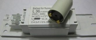
It is economically feasible to connect one throttling device to a pair of lighting fixtures at once. A standard electromagnetic ballast, in addition to the choke, is represented by a starter and a pair of capacitors.
Characteristics of electronic ballasts
Electromagnetic type chokes are characterized by affordable cost, simple design and high reliability, and the main disadvantages of such devices are presented:
- pulsating light flux, causing visual fatigue;
- about 10-15% loss of electrical energy;
- noisy operation at the starting moment;
- insufficiently stable startup in low temperature conditions;
- large size and noticeable weight;
- long start of the light source.
As a rule, the kit is represented by lamps and chokes, and replacing the balance yourself involves purchasing an element with similar parameters.
Characteristics of electronic ballast
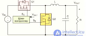
Electronic ballasts belong to the category of modern devices in which the disadvantages of an electromagnetic choke are almost completely eliminated. Schematically, such an element is a single unit that starts the lighting device and supports the combustion process by forming a certain sequence in changing the voltage level.
The advantages of electronic ballast are presented:
- any launch speed;
- no need to install a starter;
- flicker is excluded;
- maximum luminous efficiency;
- compact size and light weight of the device;
- optimal operating conditions.
This is what electronic ballast looks like
Electronic ballasts are an order of magnitude higher than electromagnetic devices, which is due to the complexity of the circuit with the presence of filters that correct the power factor of moments, an inverter and ballast. Some models of electronic devices are complemented by a system of protection against turning on the lighting device without a lamp.
The ease of use of electronic ballasts in energy-saving fluorescent lamps is due to the installation of light sources directly into the base of standard sockets.
Replacing the ignition coil
The process of replacing a part is quite simple. Opening the hood, you will immediately see the wires going to the cylinder head. Their number will coincide with the number of engine cylinders. On a 4-cylinder unit, there will accordingly be 4 wires. They are connected directly to the coil that needs to be replaced. After disconnecting the wires, loosen the fasteners securing the coil. If the bolts are stuck, apply WD-40, which can loosen the rust. After waiting a certain time, remove the element.
Before installing a new part, clean the seat from dirt, oil and rust. After this, perform the procedure in reverse order: install the part, secure it with bolts and connect the new ignition coil
It is important to install the wire in the position it was originally in
Most common malfunctions
As a rule, sources of malfunction that are associated with the operation of fluorescent lamps are represented by malfunctions in the electrical circuit of the ballast and starter. By assessing the characteristic visual effects, the causes of the malfunction can be reliably determined:
- the presence of a “fiery snake” curling inside the flask is the result of exceeding the permissible current values and instability of the electrical discharge;
- a dark bulb in the area where the output base contacts are located indicates a discrepancy between the current indicators for starting and operation with the current-voltage characteristics;
- Burnout of spirals in fluorescent lamps may result from insulating wear of the winding of the ballast.
Quite often there are problems accompanied by the appearance of a burning smell or third-party sounds. In this case, we can assume the appearance of an interturn short circuit on the induction coil.
How to check a fluorescent lamp choke with a multimeter
The most wear-resistant element in the design of luminaires with fluorescent lamps is the inductor, the breakdown of which is quite rare. A malfunction of such an element can be represented by a break or winding burnout, or violations of interturn insulation in electrical wires.
Both faults can be detected by connecting a tester in the form of a multimeter to the choke terminals to measure resistance. The presence of infinite resistance indicates a break and burnout.
Starter and choke for fluorescent lamps
As a rule, burnout is accompanied by the appearance of an unpleasant odor emanating from the part that has become unusable.
Any verification processes described above are valid only in the case of using electromagnetic ballasts, since electronic ballasts exclude the presence of a starter in the circuit.
How to check a fluorescent lamp starter
The process of checking fluorescent-type lighting devices involves not only monitoring the spiral integrity inside the bulb, but also the performance of the throttle and starter systems.
- capacitors that should not be swollen, deformed or burst under the influence of excess voltage in the electrical network;
- light source bulb, which should not be blackened.
Capacitor integrity is checked using a multimeter in ohmmeter mode with the maximum possible resistance measurement limits.
If the readings on the tester are less than 2.0 MOhm, then it can be assumed that there is an unacceptable current leakage in the capacitor. As practice shows, the best option when carrying out independent repair work is to completely replace all elements that have become unusable (starter and throttle) with new devices of a similar type.
Purpose and device
In some devices, chokes are installed in order to pass pulse currents of a certain frequency range. This range depends on the design of the inductor, that is, on the wire used in the coil, its cross-section, the number of turns, the presence of a core and the material from which it is made.
Structurally, the inductor is an insulated wire wound around a core. The core can be metal, made up of insulated plates, or ferrite. Sometimes the choke can be made without a core. In this case, a ceramic or plastic frame for the wire is used.
The throttle valve is present in the carburetor. It regulates the supply of the combustible mixture, representing a potentiometer. To check the throttle sensor in a car, determine whether the input voltage of the device corresponds to the throttle position .
Selection rules
To choose the right starting inductance, you need to pay attention to the device body. It indicates the load power that it can power. The power of the ballast depends on the cross-section of the winding wire: the larger it is, the more significant current the device can produce.
Powerful coils have significant dimensions and a higher cost, so it is necessary to optimally select the starting inductance. You can use one coil to power several lamps - this is often done in double lamps, which can often be found in office spaces.
In lamps
In luminaires designed for the use of fluorescent lamps, in addition to the lamps themselves, components such as a starter and a choke are used.
The starter, as the name suggests, starts the glow process in the lamp and does not participate further in the process. The choke functions as a current and voltage stabilizer during the entire period of the lamp's glow.
If the choke is faulty, the lamp does not light or does not burn steadily, its glow is not uniform along its entire length, and areas with a brighter glow may appear inside, moving from one electrode of the lamp to another. Sometimes you can notice the flickering effect of the light.
If the throttle is faulty, the lamp may not light up the first time, and the starter will turn on repeatedly until the lighting process finally starts. As a result, dark spots will appear on the lamp bulb where the spirals are installed. This is due to the fact that the coils operate for a longer time than is set for normal starting.
Design
An LED is a semiconductor element similar in design to a diode. When current passes through the LED, optical radiation visible to the eye is created. This part consists of:
- An anode through which a positive charge is applied.
- A cathode through which a negative charge is applied.
- Reflector of light fluxes.
- Emitting semiconductor chip or crystal.
- Glow diffuser.
This is the standard design for lamps of all shapes. To achieve brightness, manufacturers only increase the number of layers or the number of crystals. These values directly affect power.
Checking in lamps
The throttle must be checked if one of the above-described phenomena is observed when the fluorescent lamp is operating, as well as if a characteristic smell of burning insulation is noticed, sounds that are not typical for the operation of the device are observed, and also if the lamp does not turn on.
Before checking the lamp choke, the lamp itself and the starter are checked.
A malfunction of the inductor may consist of a break or burnout of the coil wire or an interturn short circuit caused by breakdown or burning of the insulation.
Both malfunctions can occur either due to a long period of use of the device, or as a result of any mechanical impact. It is possible for the coil wire to burn out as a result of supplying it with a current greater than the maximum for which the inductor is designed.
In the event of a wire break or burnout, you can identify the fault with a conventional tester or multimeter. Due to the fact that the inductor passes direct current, closing the tester circuit through the coil, you can understand by the glow of the control lamp or its absence whether there is a break or not.
If, when measured with a multimeter, the resistance is infinite, the coil wire has broken.
The simplest ways to check the serviceability of electrical radio elements
Testing wirewound and non-wirewound resistors
To check wire and non-wire resistors of constant and variable resistance, you must do the following: carry out an external inspection; check the operation of the driving mechanism of the variable resistor and the condition of its parts; using markings and dimensions, determine the nominal resistance value, permissible dissipation power and accuracy class; use an ohmmeter to measure the actual resistance value and determine the deviation from the nominal value; For variable resistors, also measure the smoothness of the change in resistance when the slider moves. The resistor is operational if there is no mechanical damage, the value of its resistance is within the acceptable limits of a given accuracy class, and the contact of the slider with the conductive layer is constant and reliable.
Checking all types of capacitors
Electrical faults include: breakdown of capacitors; short circuit of plates; change in nominal capacity beyond the tolerance due to dielectric aging, moisture, overheating, deformation; increase in leakage current due to deterioration of insulation. Complete or partial loss of capacity of electrolytic capacitors occurs as a result of drying out of the electrolyte.
The simplest way to check the serviceability of a capacitor is an external inspection, which reveals mechanical damage. If no defects are found during an external inspection, an electrical test is carried out. It includes: checking for short circuit, breakdown, integrity of leads, checking leakage current (insulation resistance), measuring capacitance. In the absence of a special device, the capacitance can be checked in other ways, depending on the capacitance of the capacitors.
High-capacity capacitors (1 μF and higher) are checked with a probe (ohmmeter), connecting it to the terminals of the capacitor. If the capacitor is working, then the arrow of the device slowly returns to its original position. If the leak is large, then the arrow of the device will not return to its original position.
Medium-capacity capacitors (from 500 pF to 1 µF) are tested using telephones and a current source connected in series to the terminals of the capacitor. If the capacitor is working properly, the moment the circuit closes, a click is heard in the phones.
Small capacitors (up to 500 pF) are tested in a high-frequency current circuit. A capacitor is connected between the antenna and the receiver. If the reception volume does not decrease, it means there are no broken pins.
Checking inductors
Checking the serviceability of the inductors begins with an external inspection, during which they are convinced of the serviceability of the frame, screen, and leads; in the correctness and reliability of connections of all parts of the coil with each other; in the absence of visible wire breaks, short circuits, damage to insulation and coatings. Particular attention should be paid to areas of charring of the insulation, frame, blackening or melting of the fill.
Electrical testing of inductors includes checking for opens, detecting shorted turns, and determining the condition of winding insulation. Checking for a break is performed with a probe. An increase in resistance means a break or poor contact in one or more wires. A decrease in resistance means the presence of an interturn short circuit. When the terminals are short-circuited, the resistance is zero.
Checking turn-to-turn short circuit
In the case of an interturn short circuit, checking with a tester will not give a result. In this case, you need to know how to check the throttle using a multimeter.
An interturn short circuit occurs when there is direct galvanic contact between two turns or when the turns come into contact with a metal core. Obviously, in this case the coil resistance decreases.
There may be a rare case when measuring the coil resistance will not give a reliable picture of its condition. This can happen when there is a break and an interturn short circuit at the same time.
In this case, the interturn short circuit may turn out to be parallel to the break, and several turns simply will not participate in the measurement. A seemingly serviceable throttle will not work correctly.
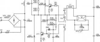
To check the coil for the presence of an interturn short circuit, an analog multimeter in milliammeter mode must be used as part of a device assembled with two transistors.
The diagram of the device is shown in the figure.
The device itself is a low frequency generator. When assembling the circuit, any transistors from the MP39-MP42 line are used (gain factor 40-50).
Diodes can be used type D1 or D2 with any index. Resistors are used of any type, designed for a power of at least 0.12 W. The device is powered from a DC source with a voltage of 7-9 V.
Signs of a broken ignition coil
How to test a transformer using a multimeter
There are several main signs of coil failure:
- back exhaust caused by some of the fuel getting into the exhaust manifold of the car;
- increased gasoline consumption - increased costs for regular car refueling;
- misfires resulting from a violation of the fuel ignition order;
- complete engine stop - the unit stalls due to unstable sparking;
- decrease in power, the appearance of strong jerks, rough idling;
- Difficulties starting the engine - occur when there is only a single faulty coil;
- Check Engine warning light signal with the corresponding fault code being stored.
The appearance of reverse exhaust
Reverse exhaust
- a specific sign of an ignition coil malfunction, which manifests itself at an early stage of such a breakdown.
It is associated with unburned gasoline entering the muffler. Because of this, the driver sees black smoke
combined with a strong smell of fuel coming from the car's exhaust pipe.
Increased fuel consumption
Increased fuel consumption may indicate problems with the coil.
. The malfunction leads to a decrease in the driver’s usual dynamics. It automatically begins to press the gas pedal harder than usual, which increases gasoline consumption. Over time, the cost of refueling a vehicle increases significantly.
Fuel misfire
The coil is one of the main devices in the car ignition
. If a breakdown occurs, the order of ignition of the fuel mixture is disrupted. As a result, a characteristic cracking sound appears. When driving, the problem is expressed in uneven operation of the engine, constant jerking. When starting the engine at idle speed, the driver will feel vibration.
Complete engine stop
If the engine stalls
while driving, the problem may be with the ignition coil. Its failure leads to unstable sparking. During subsequent attempts to start the engine, the car owner may also experience difficulties.
Jerks and loss of power
Another common sign of a breakdown is the appearance of jerks while the car is moving. The engine begins to operate unstably and vibrate at idle. Power drops noticeably, and the convenience of everyday use of the vehicle decreases. When accelerating, characteristic dips may occur.
The listed symptoms are characteristic of a breakdown of the ignition coil. This refers to physical damage to its primary or secondary winding. The device continues to function, but part of the electricity is transferred to the body. As a result, the spark plug cannot operate at full power, and engine dynamics are lost. glow plugs fail.
.
Problems starting the engine
A malfunction of the ignition system is often indicated by poor engine starting.
. Typically this situation occurs when there is one coil. The crankshaft will rotate, but the engine will not start due to lack of spark in the cylinders. The problem can be repeated many times.
Warning lamp signal
The appearance of a Check Engine light in modern cars may indicate problems with the coil. A similar alert occurs for other faults. The vehicle's ECU must store a fault code - P0351. If such signs appear, you should immediately seek diagnostics, which is carried out using a special scanner.
Sequence of action
The verification procedure is as follows:
- The Vk toggle switch turns on. In this case, the multimeter needle should deflect to the middle of the scale;
- depending on the inductance of the coil, the position of the variable resistor R5 is set. The left position corresponds to less, and the right to greater inductance. When checking coils with inductance less than 15 mH, you must additionally press the Kn2 button;
- The inductor terminals are connected to the Lx terminals and contact Kn1 is closed with a button. In this case, if there are no turns in the winding that are short-circuited with each other, the multimeter needle should deviate towards higher values or slightly deviate towards smaller values. If the winding has at least one short circuit between the turns, the arrow returns to zero.
Sometimes the cause of a coil malfunction can be a broken or damaged core. The material from which the core is made, its size and position relative to the coil affect the inductance.
Functions of ballasts
The simplest and cheapest is the electronic ballast circuit with a starter. Its work is carried out as follows. After turning on the power, voltage is supplied to the starter electrodes through the inductor winding and tungsten filaments.
The electrodes heat up very quickly, literally in a split second, after which the lighting switches on smoothly. The lamps turn on just as easily at low temperatures. Ignition is carried out under the influence of a high voltage pulse, then even combustion begins at a constant increased voltage.
What kind of lighting do you prefer?
Built-in Chandelier
Inductance check
The presence in the arsenal of a multimeter of such a useful function as measuring the inductance of the coils will be useful for checking the compliance of the inductor with the characteristics stated in the reference literature. This feature is only available on some digital multimeter models.
To use this feature, you must set your multimeter to measure inductance. The probe contacts are connected to the coil terminals. For the first measurement, the multimeter is set to its largest measurement range, and then the range is reduced to obtain a measurement of sufficient accuracy.
When carrying out all measurements, it is important not to allow your hands to touch the contacts on which certain parameters are measured, otherwise the conductivity of the human body may change the readings of the device.
Where is the ignition coil located?
In cars of earlier years, the ignition coil (or bobbin, as it used to be called) was easy to find. She was always in plain sight. As a last resort, its search could be carried out starting from the central wire of the ignition distributor.
Individual ignition coils are also easy to find: they are located above the cylinder spark plugs. But in some car models, especially with a V-shaped engine, in order to provide access to it, even to remove spark plugs, it is necessary to dismantle the intake manifold, part of the engine structural elements.
Dual ignition coils are usually located on the engine compartment bulkhead. But sometimes manufacturers can place them in places that are difficult to access for replacement and, even more so, for performance monitoring.
For example, in some Rover 200 series models the ignition coil is located under the exhaust manifold in the engine compartment between the engine and the passenger compartment. It is possible to measure its parameters when monitoring performance only from the connector of the engine control unit.
Sometimes ignition coils are mounted on the engine cylinder head (for example, some GAZ models). Although this is convenient for checking, during engine operation they heat up to a temperature of more than 100 degrees Celsius, the insulating compound dries out and cracks, which leads to a decrease in their durability.
In some cars, individual ignition coils are combined into a common, non-separable housing. Even if one coil fails, it is necessary to replace the entire expensive unit.