Ideally, in order to check the windings of an electric motor, it is necessary to have special instruments designed for this, which cost a lot of money. Surely not everyone has them in their home. Therefore, it is easier for such purposes to learn how to use a tester, which has another name: a multimeter. Almost every self-respecting home owner has such a device.
Electric motors are manufactured in various versions and modifications, and their malfunctions are also very different. Of course, not every fault can be diagnosed with a simple multimeter, but most often checking the motor windings with such a simple device is quite possible.
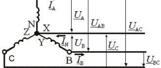
Determination of the same terminals of the stator winding of a three-phase asynchronous electric motor
If the beginnings and ends of the windings are connected at points A and B, then the voltmeter will show approximately the same voltage on each winding. If one of the windings turns out to be “inverted”, the voltage on it will be greater than on the other two. Bye everyone and good luck in the difficult business of being an electrician!
Expert opinion
It-Technology, Electrical power and electronics specialist
Ask questions to the “Specialist for modernization of energy generation systems”
How to determine the beginning and end of the windings of an electric motor: a review of techniques If instead of a triangle circuit, you connect the windings according to a star circuit, then the electric motor will not operate at full power. Ask, I'm in touch!
Types of windings
- The material of the winding wire must be uniform along its entire length.
- The shape and cross-sectional area of the wire must have a certain accuracy.
- In industrial conditions, a layer of insulation in the form of varnish must be applied to the wire intended for winding, which must have certain properties: strength, elasticity, good dielectric properties, etc.
- The winding wire must provide strong contact when connected.
If there is any violation of these requirements, then the electric current will flow under completely different conditions, and the electric motor will deteriorate its performance, that is, the power, speed will decrease, and may not work at all.
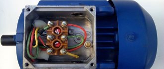
Checking the motor windings of a 3-phase motor . First of all, disconnect it from the circuit. The majority of existing electric motors have windings connected in star or delta configurations.
The ends of these windings are usually connected to blocks with terminals that have the appropriate markings: “K” - end, “N” - beginning. There are options for internal connections, the nodes are located inside the motor housing, and different markings (numbers) are used on the terminals.
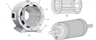
The stator of a 3-phase electric motor uses windings that have equal characteristics and properties, and the same resistance. When measuring the winding resistances with a multimeter, it may turn out that they have different values. This already makes it possible to assume that there is a malfunction in the electric motor.
Possible faults
It is not always possible to visually determine the condition of the windings, since access to them is limited by the design features of the engine. In practice, you can check the winding of an electric motor using its electrical characteristics, since all motor breakdowns are mainly detected:
- A break, when the wire is broken or burnt out, no current will pass through it.
- A short circuit caused by damaged insulation between the input and output turns.
- A short circuit between turns, with the insulation damaged between adjacent turns. As a result, damaged turns are self-excluded from operation. Electric current flows through the winding, which does not involve damaged turns that do not work.
- By breaking through the insulation between the stator housing and the winding.
The first step is to determine the motor windings
The names of the windings are also absolutely arbitrary. Although, if we take into account such a concept as phasing, then correct inclusion gives an accurate idea of in which direction the motor shaft will rotate and nothing more. Set the multimeter to dialing mode, apply one probe to any of the six wires, and use the second probe to find the end that will be dialed. And you mark this pair of ringing ends. Let these be U1 and U2. Four ends remain. Repeat the operation and mark another pair again. Let these be V1 and V2. There are still a couple of ends left, you check them just in case to be sure that the winding is in good condition and also mark them with the remaining markers W1 and W2. Now you have three windings and you know their conclusions. But you don’t know where the beginning and where the end of each winding is. In other words, you do not know which way the magnetic fluxes of these windings are directed according to the existing markings, since they are now random.
Connection diagrams for three-phase electric motors. Determination of the beginning and end of the windings
Hello dear readers and blog guests! In this post I want to talk about circuits for connecting a three-phase electric motor to a network and a method for determining the “beginnings” and “ends” of the stator winding.
In general, all terminals of electric motors must be marked (have tags). But this doesn’t always happen in real life. Often in practice there are no tags, and the leads stick out randomly from the motor box.
As a rule, the conditional “beginnings” of the windings of asynchronous electric motors are marked as C1, C2, C3, and the corresponding “ends” as C4, C5, C6. If the motor is multi-speed, then the first winding is marked 1С1….1С6, the second as 2С1….2С6, etc.
The terminals of the windings of low-power machines are marked with paint of different colors. Phase “A” is yellow, phase “B” is green and “C” is red. The ends of the windings have the corresponding color and are painted black on top.
The windings of three-phase asynchronous electric motors are assembled according to two circuits: “star” and “delta”.
To do this, all three ends or beginnings are connected together, and the remaining terminals are connected to the network phases.
If the network voltage coincides with one of the lower voltages shown on the plate, then a “triangle” connection diagram is used. In this case, the terminals of the windings are connected in this way: the end of the first winding is connected to the beginning of the second, the end of the second to the beginning of the third, the ends of the third to the beginning of the first. Common connection points are connected to the network to the phases.
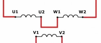
Very often, in many three-phase asynchronous electric motors, the beginnings and ends of the windings are output to the terminal board as follows, as shown in the figure below
Here, to connect the windings according to the “star” circuit, it is necessary to short-circuit the three lower terminals (the upper ones are also possible) and apply them to the remaining terminals of the network phase. To connect according to the “triangle” scheme, you need to connect a pair of clamps vertically and connect the network phases to them. The figure below shows this.
If you connect the windings in a star pattern instead of a triangle circuit, the electric motor will not operate at full power. It will only deliver 1/3 of its rated power. If, at a given network voltage, an electric motor must operate in a star circuit, then in a triangle circuit it is prohibited to be connected to the network. It will quickly overheat and burn! Be careful!
If you want to change the direction of rotation of the electric motor shaft to the opposite, then swap any two phases of the network.
What kind of lighting do you prefer?
Built-in Chandelier
Now let's imagine the following situation. You want to connect an electric motor, open the terminal cover and see 6 pins without any markings or colors. What to do? Quickly close the lid and run away from such electrical equipment! )) the sediment of cedar pine will help you concentrate. But seriously, there are three ways to determine the beginnings and ends of windings.
First you need to identify pairs of winding terminals belonging to different phases. To do this, you can use a 220-volt test lamp, but it is safer to use a tester for this purpose in the ohmic resistance measurement mode (multimeter). I will not describe this process in more detail, since I hope that you already have some basics under your belt.
Expert opinion
It-Technology, Electrical power and electronics specialist
Ask questions to the “Specialist for modernization of energy generation systems”
Connection Diagrams for a Three-Phase Asynchronous Electric Motor and Description If the engine starts and runs normally, then the beginnings and ends of the windings are determined correctly, if the engine hums a lot and does not develop the proper speed, then there is an error somewhere. Ask, I'm in touch!
How to determine the beginning and end of the phases of the winding of an asynchronous motor
Mains voltages and diagrams of the stator windings of the electric motor
If the electric motor's passport indicates, for example, 220/380 V, this means that the electric motor can be connected to both a 220 V network (winding connection diagram - triangle) and a 380 V network (winding connection diagram - star). The stator windings of an asynchronous electric motor have six ends.
According to GOST, the windings of an asynchronous motor have the following designations: Phase I – C1 (start), C4 (end), Phase II – C2 (start), C5 (end), Phase III – C3 (start), C6 (end).
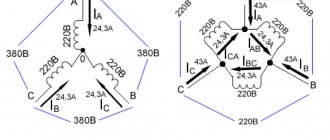
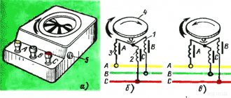
Rice. 1. Connection diagram of the windings of an asynchronous motor: a – in a star, b – in a triangle, c – execution of the “star” and “delta” circuits on the terminal board.
If the voltage in the network is 380 V, then the stator windings of the motor must be connected in a star configuration. In this case, either all the beginnings (C1, C2, C3) or all the ends (C4, C5, C6) are collected into a common point. A voltage of 380 V is applied between the ends of the windings AB, BC, CA. At each phase, that is, between points O and A, O and B, O and C, the voltage will be √ 3 times less: 380/√ 3 = 220 V.
If the voltage in the network is 220 V (with a voltage system of 220/127 V, which is currently found almost nowhere), the stator windings of the motor must be connected in a “triangle” pattern.
At points A, B and C, the beginning (H) of the previous winding is connected to the end (K) of the subsequent winding and to the network phase (Fig. 1, b). If we assume that between points A and B phase I is switched on, between points B and C – phase II, and between points C and A – phase III, then in the “triangle” scheme the following are connected: the beginning of I (C1) to the end of III (C6) , beginning II (C2) with end I (C4) and beginning III (C3) with end II (C5).
On some motors, the ends of the winding phases are brought out onto the terminal board. According to GOST, the beginnings and ends of the windings are output in the order shown in Figure 1, c.
If it is now necessary to connect the motor windings according to the “star” circuit, the terminals to which the ends (or beginnings) are brought out are connected to each other, and the network phases are connected to the motor terminals to which the beginnings (or ends) are brought out.
When connecting the motor windings in a “triangle”, the terminals are connected vertically in pairs and the network phases are connected to the jumpers. Vertical jumpers connect the beginning of I to the end of phase III, the beginning of II to the end of phase I, and the beginning of III to the end of phase II.
When determining the winding connection diagram, you can use the following table:
Voltage indicated in the motor passport, V
Network voltage, V
Determination of matched terminals (beginnings and ends) of the stator winding phases.
The terminals of the stator windings of the motor usually have standard markings on metal crimp rings. However, these crimp rings are lost. The need then arises to define consistent conclusions. This is done in this order.
First, using a test lamp, pairs of terminals belonging to individual phase windings are determined (Fig. 2).
Rice. 2. Determination of phase windings using a test lamp.
One of the six terminals of the motor stator winding is connected to the network terminal 2, and one end of the test lamp is connected to the other network terminal 3. The other end of the test lamp is alternately touched to each of the other five terminals of the stator windings until the lamp lights up. If the lamp lights up, it means that the two terminals connected to the network belong to the same phase.
Second way
We connect any two “found” phase windings in series and connect 220 V to the resulting free ends, and connect a test lamp to the remaining third winding and briefly apply 220 V. We remember how the lamp lights up.
Now we change the connection of the windings that are connected in series, that is, we swap the ends of the second winding and again supply power. The light bulb should light up differently, either brighter or weaker. If it lights up brighter, then our windings are connected in series, in the order beginning - end - beginning - end. So we sign them. We already clearly know two windings.
Now we connect any of the known ones to the unknown one and again we supply 220 V to this pair, and a lamp to the free one. Turn on the power again. Now you can immediately see from the brightness of the filament how the windings are turned on. We apply the appropriate inscriptions.
Transformation method
If the control lamp does not light up, there are two “ends” or two “beginnings” at the common point of the connected phase windings. In this case, the magnetic fluxes cancel each other (Fig. 1, b), therefore, there is no EMF in the third winding - the lamp does not light up, the voltmeter needle does not deviate. The terminals of one of the phase windings are swapped and the circuit is turned on again.
If a lamp or voltmeter detects the presence of voltage in the third winding, then the output of one of the windings connected at point O is marked as “end”, the output of the other as “beginning”.
Then assemble the circuit shown in Fig. 1, c. The lamp (or voltmeter) is connected to one of the two windings with already matched leads and the beginning and end of the third winding are determined, as described above.
Expert opinion
It-Technology, Electrical power and electronics specialist
Ask questions to the “Specialist for modernization of energy generation systems”
How to find the beginning and end of an electric motor winding - expert advice We will need a regular 4.5 V coin cell battery and a combination tester or DC milliammeter. Ask, I'm in touch!
Conclusions of an asynchronous motor. Marking of asynchronous motor terminals
There are various markings for the terminals of the motor windings. Domestic markings from C1 to C6 and international, which you see in the figure.
Nowadays, both markings are found, but for “training” we will use new designations as they are more descriptive. Earlier, I already said that the beginning and end of the windings are absolutely conditional concepts, the main condition that plays an important role is such a connection of the windings when the magnetic fluxes are not directed in the opposite direction. If two identical flows are sent counter, they seem to destroy each other. We need to obtain a consistent direction of magnetic fluxes. The motor has three windings. Roughly speaking, a motor is a transformer with three windings and a stator core. Thus, the windings in the motor are connected by a magnetic flux that flows through the stator, and it is created by a current that flows through the windings. The rotor is just a pleasant “yummy”, the presence of which allows you to convert electrical energy into mechanical energy.
Pin selection method
The pin selection method is convenient to use when determining the “beginnings” and “ends” of motors with power up to 3.5 kW. To implement it, neither a lamp nor a voltmeter is needed, which is most acceptable for V.I. Bondarenko, since he lives in a village where it is probably difficult to find a voltmeter.
Most often, this task is assigned to a winding repairman - a specialist who deals only with restoring the functionality of the motor windings. But having the necessary consumables, a special machine and certain knowledge in electrical engineering, you can start repairing the machine yourself.
The step-by-step instructions for winding the motor are as follows:
- Inspect the mechanism according to the diagrams presented above, identify problem areas, and outline the scope of work.
- Prepare consumables (suitable type of wire, insulation and connecting impregnation).
- Prepare the tilter (winding machine) for work.
- Securely secure the engine starter to the car.
- Make appropriate winding.
- Thoroughly coat the entire surface with impregnating agent.
- Install the insulating layer.
- Saturate the insulation.
- Dry the device in a special drying cabinet.
- Check the quality of the produced winding.
Subject. Study of a three-phase asynchronous motor using the direct load method.
Goal of the work. Study the design of a three-phase asynchronous motor with a squirrel-cage rotor, learn the techniques of experimentally checking the designations of the stator winding terminals and experimentally studying an asynchronous motor using the direct load method.
Familiarize yourself with the design of the engine and the device for its load; write down the engine nameplate data and the data of measuring instruments and adjustment devices.
Rice. 1.1. Connection diagram of a three-phase asynchronous motor with a squirrel-cage rotor
Experimentally check the designation of the stator winding terminals.
Assemble the circuit according to Fig. 5.1 and after checking it by the teacher, carry out a test start and reversal of the engine.
Take data and plot engine performance characteristics.
Draw up a report and make a conclusion about the work done.
Repeat theoretical material [5]: operating principle and structure of a three-phase asynchronous motor; the concept of sliding; electromagnetic torque of an asynchronous motor; dependence of torque on slip; overload capacity of an asynchronous motor; performance characteristics of a three-phase asynchronous motor.
Prepare a table in your workbook for recording the results of the experiment and a coordinate grid for constructing performance characteristics.
Rice. 1.2. Schemes for identifying and marking the terminals of the stator phase windings.
If the preliminary marking of winding terminals A
and
B
was
correct,
then the voltmeter connected to the terminals of phase
C
will not show voltage (the lamp will not light up).
This is explained by the fact that the axis of the resulting flux of the phase windings Au5F = Fl + Fv is directed at an angle of 90° to the axis of the phase winding C
and therefore does not induce an EMF in it.
If the preliminary marking of the terminals of one of the windings, for example winding B,
turned out to be
incorrect
and the diagram looked like shown in Fig.
5.2, c,
then the axis of the resulting flux of windings
A
and
B
coincides with the axis of phase winding
C
and induces some EMF in this winding, while the voltmeter at the terminals of winding C will show the voltage (the lamp will light up).
Switching diagram and test start of the engine. The motor switching circuit (see Fig. 5.1) contains a two-element PW wattmeter designed to measure the active power consumed by the motor from the network. The current coils of this wattmeter are connected to the network through measuring current transformers.
where to,
— transformation ratio of the current transformer;
Cw
- wattmeter division price, W/div.;
Expert opinion
It-Technology, Electrical power and electronics specialist
Ask questions to the “Specialist for modernization of energy generation systems”
How to determine a malfunction We connect any two phase windings found in series and connect 220 V to the resulting free ends, and connect a test lamp to the remaining third winding and briefly supply 220 V. Ask, I’m in touch!
Designation of winding terminals of asynchronous machines
GENERAL ISSUES
TESTING OF ASYNCHRONOUS MACHINES
1.1. Nominal values and basic definitions
According to their design, asynchronous machines are of three-phase and single-phase current, with phase and squirrel-cage rotors, for general industrial and special purposes. Asynchronous machines can operate in motor, generator and electromagnetic brake modes; can be excited from both the stator and rotor sides.
The rated data of an electrical machine are the data indicated on the nameplate and characterizing its rated operating mode: rated power, rated voltage, rated current, rated speed, rated efficiency and power factor. The term “nominal” can also be applied to data not indicated on the nameplate of an electrical machine, but relating to its rated operating mode, for example: rated torque, rated slip. The nominal data of the machine refers to its operation at altitudes above sea level of up to 1000 m and at ambient temperatures up to +40°C.
The nominal operating mode of an electric machine is the mode for which the machine is intended by the manufacturer and in which it must operate throughout its entire service life. According to GOST 183-74 “Rotating electric machines. General technical conditions" consider the following nominal modes of an electric machine: continuous (S1); short-term (S2) and intermittently (S3).
The short-term nominal operating mode of an electric machine is characterized by a working period of 10, 30, 60, 90 minutes, respectively.
The intermittent-short-term operating mode is characterized by a relative ON duration (DS), i.e. the ratio of the duration of the working period to the duration of the cycle (the total duration of the working period and pause). According to the standard, the PV is 15, 25, 40, 60% with a duration of one cycle of no more than 10 minutes, unless otherwise specified in the technical specifications or factory requirements.
The load of an electric machine is the power that the electric machine develops at a given time. The load is expressed in watts or kilowatts, and also as a percentage or fraction of the rated power. The load can be specified by the current consumed or supplied by the electrical machine at a given time, and is expressed in amperes, as a percentage or as a fraction of the rated current. The engine load is determined by the amount of braking torque on the output shaft. To change the engine load, you must change the braking torque on its shaft.
The direction of rotation of an electric motor with a horizontal shaft is determined from the side where it is connected to the working mechanism: clockwise - right rotation, counterclockwise - left rotation.
Designation of winding terminals of asynchronous machines
In electrical machines, winding terminals must be designated in accordance with GOST 183-74 for machines developed before 1987 or being modernized, and in accordance with GOST 26772-85 “Rotating electric machines. Designation of terminals and direction of rotation" for machines manufactured from 01/01/87.
According to GOST 183-74, the terminals of asynchronous machines are designated as follows: stator windings - the letter “C”; rotor windings - letter “P”. Three-phase windings, in addition to letters, are designated by numbers: the beginnings of the phases – by the numbers “1, 2, 3”, the ends of the phases – by the numbers “4, 5, 6”; the zero point (regardless of whether it is grounded or not) is numbered “0”.
If a three-phase machine does not have sectioned and composite windings on the stator, then the designations of the winding terminals on the stator must be made in accordance with Table. 1.1. The designations of the stator winding terminals of single-phase machines are made according to the data given in table. 1.2.
According to the standard, the contact rings of the rotors of three-phase asynchronous motors are designated by letters corresponding to the designations of the rotor winding terminals connected to them (Table 1.3). In this case, the rings are arranged in phase order, and ring P1, corresponding to the first phase, should be the furthest from the rotor winding. With three outputs, the winding zero point is not output.
The corresponding tables show designations in accordance with GOST 26772-85.
Table 1.1. Names of stator winding terminals of asynchronous machines and their designations
| Winding connection diagram | Number of pins | Name of phase and output | Pin designations | ||
| GOST 183-74 | GOST 26772-85 | ||||
| Start | end | Start | end | ||
| Open circuit | First phase | C1 | C4 | U1 | U2 |
| Second phase | C2 | C5 | V1 | V2 | |
| Third phase | C3 | C6 | W1 | W2 | |
| Star connection | or | First phase | C1 | U | |
| Second phase | C2 | V | |||
| Third phase | C3 | W | |||
| Zero phase (star point) | N | ||||
| Triangle connection | First conclusion | C1 | U | ||
| Second conclusion | C2 | V | |||
| Third conclusion | C3 | W |
Table 1.2. Designation of terminals of single-phase machines
| Number of pins | Name of stator winding terminals | Pin designation | ||
| GOST 183-74 | GOST 26772-85 | |||
| Start | end | Start | end | |
| Main winding | C1 | C2 | U1 | U2 |
| Auxiliary winding | IN 1 | AT 2 | Z1 | Z2 |
Table 1.3. Designation of rotor winding terminals
| Number of pins | Name of phase and output | Pin designation | |
| GOST 183-74 | GOST 26772-85 | ||
| 3 or 4 | First phase | P1 | K |
| Second phase | P2 | L | |
| Third phase | P3 | M | |
| Zero phase (star point) | Q |
Test methods for asynchronous machines
When testing asynchronous motors, the tests of no-load, short circuit and direct load close to the rated load are of greatest importance [1]. To effectively use the experimental results, it is also necessary to know the value of the active phase resistance of the stator winding of the machine.
All methods used in industrial testing of electrical machines are summarized in GOST 11828-86 “Rotating electric machines. General test methods". Special standards regulate specific test methods for this type of electrical machine. For asynchronous machines, GOST 7217-87 “Rotating electric machines” has been developed. The motors are asynchronous. Test methods”, as well as a number of others.
No-load and short-circuit tests are widely used when testing asynchronous motors of all powers and types. The results of these experiments are especially valuable in cases where it is not possible to test the engine under direct load. For asynchronous motors, using data from the experience of no-load, short circuit and the value of the active resistance of the stator winding phase, it is possible to construct a pie chart from which the values of efficiency, power factor, slip, starting current, starting torque, maximum torque, etc. are determined. .
Direct load experience makes it possible to determine the main indicators of the engine. In this case, the engine load is carried out using any braking device on the engine shaft. This method is widely used when testing low and medium power engines.
The main indicators of asynchronous motors, obtained from direct load experience or found from a pie chart, must be checked for compliance with the requirements of GOST 183-74 given in table. 1.4. In cases where permissible deviations are indicated with one sign, only with a plus or only with a minus, the deviation in the opposite direction is not limited. Certain types of machines may be subject to higher requirements in the standards or technical specifications of manufacturers. Given in table. 1.4 data corresponds to the nominal operating mode of the machine. If any parameter deviates, the measurement results must be reduced to the rated values of voltage, network frequency and motor power.
Table 1.4. Deviations in the performance of asynchronous motors allowed by GOST 183-74
| The name of indicators | Permissible deviations |
| Efficiency factor (COP) of electric machines* with power up to 50 kW | – 0.15 (1 – η) |
| Power factor (cosφ) of asynchronous motors** | – (1 – cosφ)/6, but not less than 0.02 and not more than 0.07 in absolute value |
| Slip (S) | ± 20%, minus sign only for electric motors with increased slip |
| Initial starting current of motors with power more than 0.6 kW at f=50 Hz (short-circuit rotor) | +20 % |
| Initial starting torque of asynchronous motors at frequency f=50 Hz | – 15 % |
| Maximum torque of asynchronous motors | – 10 % |
Notes:
*With rounding of permissible deviations to the third decimal place.
**The permissible deviation does not apply to single-phase asynchronous motors with a working capacitor.
Idle experience
Idle mode is a mode when the rotor of an asynchronous motor rotates in the absence of mechanical load on the shaft. In this case, the rotor speed is close to, but not equal to, the synchronous speed, and the rotor current is close to zero. The no-load characteristics represent the dependences of the current I0, power consumption P0 and power factor cos φ0 on the input voltage U10 when the engine is idling:
I0; P0; cos φ0 = f(U10).
After starting the engine, it is necessary, in accordance with the recommendations of GOST 7217-87 “Rotating electric machines. The motors are asynchronous. Test methods”, allow the engine to run without load for 15–30 minutes (at a rated engine power of up to 10 kW) before conducting the idle test. When taking idle characteristics, the voltage supplied to the engine changes from U10 = (1.1 – 1.3)U1Н to U10 = (0.2 – 0.4)U1Н so as to obtain approximately 6 – 8 points. For some types of motors (usually with a squirrel-cage rotor), when the voltage decreases, the rotor speed noticeably decreases and an increase in the current consumed from the network is observed. In this case, during the idle test, the reduction in voltage at the motor terminals is stopped. These are the idle speed limit points.
The basic view of the idle speed curves is shown in Fig. 1.1.
Power P0 at no-load changes with increasing voltage according to a quadratic dependence, since this is associated with a change in losses in steel, which are proportional to the square of the voltage. The remaining losses are practically unchanged in the region of constant shaft rotation speed (mechanical and additional losses) or are quite small due to the low no-load current (electrical losses in the stator winding rel = m I02 r1). The change in no-load current I0 and power factor cos j0 is determined mainly by the reactive component of the current, which creates a magnetic field in the machine and corresponds to its magnetization curve.
Short circuit experience
The short circuit mode of an asynchronous motor is the mode in which the rotor is braked and closed on itself. If the rated voltage is applied to the motor terminals, then the current IKN consumed from the network is several times higher than the rated current, IKN = (4 – 7) IH. Therefore, when conducting a short circuit experiment, a reduced voltage is applied to the stator winding so that the current does not exceed 1.1 IN.
The short circuit characteristics represent the dependence of the current IK, power consumption PK and power factor cos jK on the supplied voltage UK during a motor short circuit:
IK; PK; cos jК = f (UК).
The magnitude of the inductive short circuit resistance of an asynchronous machine xK, as well as the short circuit current, depend on the relative position of the stator and rotor teeth. Therefore, at reduced voltage, slowly turning the rotor, it is necessary to note the highest and lowest values of the stator current using an ammeter. Then the rotor should be fixed motionless using a mechanical device in a position corresponding to the average current value.
The voltage is increased to a value at which the short circuit current reaches the value IK = 1.1 IH, and the instrument readings are recorded. The applied voltage is then reduced and instrument readings are recorded. 5 - 6 measurements are obtained when the short circuit current is reduced to zero. Taking characteristics from a higher current value to a smaller one is necessary to maintain the stability of the temperature regime of the machine. As the current increases, as it reaches higher values, the temperature of the machine increases significantly compared to the beginning of the experiment, since losses in copper are proportional to the square of the current. The principle view of the short circuit characteristics is shown in Fig. 1.2.
The short circuit power RK, determined by losses in the windings of the machine, is practically proportional to the square of the short circuit voltage, since the short circuit current IK is almost proportional to the voltage. This is explained by the strong demagnetization of the machine by rotor currents, the low main magnetic flux and weak saturation of the machine’s magnetic circuit.
Table 2.1. Technical data of electrical machines of direct and alternating current, angular displacement transducer
| DC machine (type 101.2) | |
| Rated power, W | |
| Rated armature voltage, V | |
| Rated armature current, A | 0,56 |
| Resistance of armature winding and brush contact Ra, Ohm | 70 – 80 |
| The excitation winding has two windings – E1–E2 E3–E4 | |
| Excitation of the machine: independent or parallel - the excitation windings are connected in series; serial - the field windings are connected in parallel. | |
| Rated current of a separate excitation winding, A | 0,25 |
| Voltage of one excitation winding Uf, V | 110 V |
| Resistance of one excitation winding Rf, Ohm | |
| Efficiency, % | 57,2 |
| Direction of rotation | reverse |
| Rated rotation speed, min–1 | |
| Operating mode | motor, generator |
| AC machine (type 102.1) | |
| Number of phases on the stator | |
| Number of phases on the rotor | |
| Stator winding connection diagram | |
| Rotor winding connection diagram | Y |
| Phase winding resistance Ra, Ohm | |
| Current frequency, Hz | |
| synchronous machine | |
| Rated active power, W | |
| Rated voltage, V | |
| Rated stator current, A | 0,26 |
| No-load excitation current, A | 1,6 |
| Rated excitation voltage, V | |
| Rated excitation current, A | 1,85 |
| Rated rotation speed, min–1 | |
| asynchronous machine | |
| Rated useful active power, W | |
| Rated voltage, V | |
| Rated stator current, A | 0,35 |
| Efficiency, % | |
| cos jH | 0,73 |
| Rated rotation speed, min–1 | |
| Rotary transducer (type 104) | |
| Model | BE 178A |
| Number of output channels | |
| Number of pulses per revolution in a series | |
| Shaft rotation speed range, min-1 | 0 . . . 6000 |
Lists of stand equipment data are given in Table. 2.2.
Table 2.2. List and technical data of stand equipment
| Designation/Type | Name | Options |
| G1/201.2 | Three-phase power supply | ~ 400 V / 16 A |
| G2/206.1 | DC power supply | = 0 to 250 V/ 3 A (armature) = 220 V/ 1 A (excited) |
| G3/209.2 | Synchronous machine exciter | = 0 to 40 V / 3.5 A |
| A2/347.1 | Three-phase transformer group | ~ 3´80 VA/ 230 V/242,235, 230, 226, 220, 133, 127 V |
| A6, A8 /301.1 | Three pole switch | ~ 400 V / 10 A |
| A9/307.1 | Rheostat in the rotor circuit of an AC machine | 3 ´ 0…40 Ohm / 1 A |
| A10/306.1 | Active load | 220 V / 3´0…50 W; |
| A11/308.1 | Rheostat | 0…2000 Ohm / 0.3 A |
| A13/323.2 | Rheostat | 2×0…100 Ohm / 1 A |
| R1/508.2 | Multimeter block | = ~ 0 to 1000 V / 0 to 10 A / 0 to 20 MOhm |
| R2/507.2 | Active and reactive power meter | 15; 60; 150; 300; 600 V / 0.05; 0.1; 0.2; 0.5 A. |
| R3/506.2 | Speed indicator | minus 2000…0…plus 2000 min-1 |
To operate the stand, it is necessary to make an electrical diagram of connections between the thermal protection of the AC machine and the three-phase power supply unit (Fig. 2.1).
An electronic multimeter is used to measure electrical quantities (current, voltage and ohmic resistance). To connect it to the circuit, you must do the following:
— set the type of current (direct / alternating);
— select the measurement range according to the expected measurement result;
— correctly connect the multimeter clamps to the circuit being measured (Fig. 2.2 – 2.4).
A block of three multimeters is installed on each stand, allowing you to have three instruments for measuring current and voltage in any quantitative combination of ammeters and voltmeters within three.
Rice. 2.2. Attaching a multimeter (like a voltmeter) to measure voltage
A direct current generator of independent or parallel excitation is used as the load of an asynchronous motor. The type of excitation does not matter in this case. Schematic electrical circuits of the generator with independent and parallel connections are shown in Fig. 2.5.
a) b)
Rice. 2.5. Connection diagram in a DC generator
with independent (a) and parallel (b) excitation
The devices shown in the diagram in the generator excitation circuit are not needed in this laboratory work and can be used to control the current in the windings of an asynchronous machine. It is only necessary to ensure that the voltage on the field winding of a DC machine does not exceed 230 V. A voltmeter that measures the voltage at the armature terminals should also be used to measure the voltage at the terminals of an asynchronous machine. It can be switched back to a DC machine if necessary. An ammeter in the armature circuit is necessary to monitor the generator load.
To study the operation of an asynchronous machine in generator mode, a motor with continuously variable shaft speed control is required. A DC machine is used as such a motor. Possible electrical connection diagrams in a DC motor are shown in Fig. 2.6. Everything said above about the use of devices is also true for the above diagrams of the machine in engine mode.
a) b)
Rice. 2.6. Connection diagram in a DC motor
with independent (a) and parallel (b) excitation
Independent excitation of a DC motor is preferable, since it allows you to regulate the rotation speed of the unit shaft more accurately than with parallel excitation, which is important when studying the generator mode of an asynchronous machine.
When working with the stand, several rules must be followed.
Before assembling the circuit, make sure that all switches are in the “OFF” position, the power supply mode switches are in the “MANUAL” position, and the DC power supply voltage regulator is turned to the extreme left position, corresponding to zero voltage.
The grounding points of the blocks used, directly or through the grounding points of other blocks, must be connected to the grounding points of the three-phase power supply of the stand.
During assembly, the circuits should be installed correctly, and after assembly, check again the operating modes of the measuring instruments, the type of current and the range of measured values.
Before turning on the stand, the circuit must be checked by a laboratory engineer or teacher.
Do not turn on the main power supply of the stand when the DC power supply is turned on or when there are a large number of units with switches in the “ON” position. When a three-phase power source is turned on, this leads to an inrush of current, tripping of a residual current device (RCD) and tripping of circuit breakers in one or two to three phases.
WITH PHASE ROTOR
Goal of the work
The purpose of the work is to test an asynchronous machine with a wound rotor in motor and generator modes, idle and short circuit modes, become familiar with the method of starting the machine, learn how to construct a pie chart and use it.
Work program
1. Familiarize yourself with the design of the machine and write down its passport data.
2. Measure and bring the phase resistance of the stator and rotor windings to an operating temperature of 75°C.
3. Determine the transformation ratio of phase voltages of a motor with a wound rotor.
4. Start up and change the direction of rotation of the engine.
5. Remove and plot engine idle characteristics:
I0; P0; Q0; n0; cosφ0 = f (U0).
6.Remove and plot short circuit characteristics:
IK; PK; QK; cosφК = f (UK).
7.Remove and plot the operating characteristics of a machine with a wound rotor in motor and generator modes:
I1; P1; Q1; M2; n; s; cosφ; η = f (P2).
8. Based on the data from no-load and short-circuit experiments, construct a pie chart of an asynchronous machine and use it to determine the operating parameters in rated load mode and all types of losses.
Laboratory stand
The installation, the electrical diagram of which is shown in Fig. 3.1, consists of an asynchronous machine and a DC load generator coupled to it. The shafts of the engine and generator are connected by a coupling; there is a special device for “locking” the shafts, which is necessary when conducting a short circuit experiment.
The motor under test is connected to a three-phase voltage source (G1/201.2) through two series-connected transformers (A2/347.1), a linear reactor (A14/314.2) and a three-pole switch (A6/301.1). The voltage on the motor and the current it consumes are measured by two devices in the multimeter block (P1/508.2). The third device is connected as an ammeter to the armature circuit of the DC generator. An active and reactive power meter (P2/506.2) is included in one of the motor phases. The electrical circuit is also shown in appendix. In Fig. B.1 in A4 format.
The vehicle specifications are given in table. 2.1. The designation of the terminals of the stator and rotor windings of an asynchronous motor corresponds to table. 1.1, 1.3. The load in the phases of an asynchronous motor can be considered symmetrical, so the current, voltage and power of the motor are measured in one phase. To increase the accuracy of measurement, the wattmeter has a switch switch in the “x10” position, which reduces the division price by 10 times, that is, the measured data according to the limit value of the scale Ppr = Upr ∙ Ipr, obtained from the limit values of voltage Upr and current Ipr , should be divided by 10. The value of the reactive power readings does not change, and the limit value of the scale is determined by the established limit values of voltage and current Qpr = Upr ∙ Ipr.
A direct current generator with an independent excitation winding (OB) is connected to the load resistance RN (A10/306.1). The change in the load on the shaft of an asynchronous motor is carried out by regulating the excitation current of the load generator, which leads to a change in the armature current in it, which creates a braking torque relative to the drive motor, the role of which is performed by the asynchronous machine under study. The excitation current is adjusted by turning the DC source adjustment knob clockwise (G2/206.1). At the beginning of regulation, a “dead zone” is noticeable.
To implement the generator mode of an asynchronous machine, a direct current generator with independent excitation is connected to parallel operation with the network and subsequently serves as a drive motor when the asynchronous machine is switched to generator mode. The load of the asynchronous generator is changed by regulating the voltage on the armature winding of the DC motor, which leads to a change in the armature current of the drive motor, which creates the torque of the electric machine unit, in which the asynchronous generator under study plays the role of load.
The protective grounding sockets “ ” of all used devices must be connected to the “PE” socket of the three-phase power supply G1. Before starting work, set the operating mode switches of the DC source G2 and switch A6 to the “MANUAL” position. In three-phase transformer groups A2 and A7, set the rated voltage of the windings to 220 V.
Guidelines
Idle experience
The idle characteristics represent the dependences of current, active and reactive power, shaft speed and power factor on the voltage supplied to the engine in idle mode:
I0; P0; Q0; n0; cosφ0 = f (U0).
The procedure for conducting the idle test is set out in paragraph 1.5 of these guidelines. Instruments that measure current, power and voltage in motor circuits are selected according to the rated voltage and the value of the no-load current, which for asynchronous motors is 25–50% of the rated current. The engine under study has IN = 0.35 A and UNL = 127 V. After starting the engine, the starting resistances in the rotor circuit are brought to zero. When taking characteristics in the idling mode of the engine, the supplied voltage U0 changes from an increased value, approximately 10 - 20% above the nominal U0 = 1.2 UН, to a value U0 = 0.4 UН, at which stable operation of the engine is still possible. A further decrease in voltage leads to a noticeable decrease in the shaft speed and an increase in the current consumed from the network. To control this effect, it is useful to remove the dependence of Q0 and the rotation speed n0 of the motor shaft on the no-load voltage. As soon as the current consumed from the network begins to increase as the voltage decreases, further voltage reduction should be stopped and the experiment should be interrupted.
The voltage on the motor is changed by switching the taps of the windings of three-phase transformer groups on the primary and secondary sides. It should be borne in mind that switching the voltage on the primary side of the transformer towards higher voltages leads to a decrease in the voltage on the secondary side. On the secondary side of the transformer, to reduce the voltage on the motor, the switch should be set to lower values. Over the entire measurement range, 6–7 measurements are taken. In this case, it is imperative to remove points at a voltage slightly higher than the nominal voltage and below half of its nominal value. Enter the measurement data into the table. 3.1.
The following designations are used in the table: U0Л – line voltage of the network, V; I0Л – line current of the network, A; PW0 – active power of one phase, W; QW0 – reactive power of one phase, var; n0 – shaft rotation speed, rpm. The remaining quantities are explained during the calculation.
Table 3.1. Idle characteristics
| From experience | Based on | |||||||||
| U0Л, B | I0L, A | PW0, W | QW0, var | n0, rpm | U0Ф, B | Q0, var | Р0, W | rel1, W | rmx+rst+rd W | cosφ0 |
It is better to carry out real tests of an asynchronous motor using measuring kits K50 or K505, with which currents, voltages and powers can be measured in each phase separately without rebuilding the circuit. The no-load current and voltage are taken as the arithmetic average values of the phase currents and voltages. Idle power P0 is determined by summing the power modules of all phases. Measurements using measuring kits are lengthy, but they allow you to obtain more accurate and reliable information about the machine (symmetry of voltages and currents, equality of winding phase resistances, etc.). Violation of the symmetry of voltages and currents indicates the presence of turn or phase short circuits in the motor windings. These measuring sets are also used when testing the engine in all other operating modes.
Processing of test results. The stator windings of an asynchronous motor are connected in star (Y). Therefore, the linear voltage of the network U0Л is equal to the linear voltage of the motor and will be determined by the voltmeter reading.
The linear no-load current I0L , equal to the phase current I0Ф = I0L, will be determined by the readings of the ammeter connected to the circuit. The power consumed by the motor from the network is equal to triple the reading of a single-phase wattmeter, P0 = 3PW0. The consumed reactive power is determined similarly, Q0 = 3QW0.
After determining the basic values of the idle mode, the phase voltage of the motor and the power factor are calculated:
; .
Electrical losses in the stator winding of the motor, the sum of losses in steel, mechanical and additional losses of the machine will be determined as
rel1 = 3(I0Ф)2 r1 75 ; pΣ = rst + rmx + rd = P0 – rel1.
The following designations of quantities are accepted: rel1 – electrical losses in the stator winding, W; I0Ф – phase current equal to the line current measured by an ammeter (I0Ф = I0Л), star connection (Y), A; r1 75 – active resistance of the winding phase, reduced to an operating temperature of 75°C (see clause 1.4), Ohm; рΣ – sum of engine losses in steel, mechanical and additional, W; pst – losses in the steel of the stator core, W; рмх – mechanical losses, W; rd – additional losses, W; рд = 0.005 рН; P0 – total active idle power, W.
Losses in the rotor winding during no-load are usually neglected, since the no-load current of the rotor is small, and losses in the steel of the rotor core are negligible up to slip s = 0.2, at which the magnetization reversal frequency does not exceed 10 Hz. The calculated data should contain results that make it possible to obtain, from the constructed experimental curves, data at points corresponding to the rated voltage U = UH and a voltage equal to half of its nominal value, U = 0.5 UH.
Based on the results obtained, dependencies I0 are constructed; P0; Q0; n0; cosφ0 = f (U0) on the scale diagram according to the requirements for the technical report [2, 3] (Fig. A.2). The main dependencies obtained in the experiment are shown in Fig. 1.1. The unused calculation results will be needed later to construct a pie diagram of the engine.
Short circuit experience
The specifics of conducting a short circuit experiment are set out in paragraph 1.5 of these guidelines. The motor rotor winding is short-circuited - the starting resistance in the rotor phases is brought to zero, the motor rotor is locked. Before starting the experiment, the voltage supplied to the stator winding must be reduced to the minimum possible value, preferably to zero. You should verify this by connecting only a voltmeter to the power supply terminals (Fig. 3.1, block A6) with the engine turned off. The voltage on the motor is changed by installing switches of the primary and secondary windings of three-phase transformers on the corresponding taps. The lowest voltage on the motor is achieved by installing the switches of the primary windings on taps of 245 V, and the secondary switches - 133 V. Linear reactor A14 must be included in the circuit. It serves to limit currents in circuits and further reduce the voltage at the motor terminals in short circuit mode.
The values of inductive reactance xK and current IK of the motor in short circuit mode depend on the relative position of the rotor and stator teeth. Therefore, a small voltage should be applied to the stator winding, at which the rotor cannot yet turn, but the current in the stator winding can be measured using the switched on ammeter. Slowly turning the rotor by hand or with a special device for high-power motors, find the position corresponding to the average value of the current in the stator winding. In this position, the rotor is secured with a locking device. In a motor used in a laboratory, the position of the rotor has very little effect on the motor parameters. Therefore, special installation of the rotor relative to the stator is not necessary.
When conducting a short circuit experiment, the network voltage, after connecting a stopped motor, is quickly increased to a value at which the motor current for a given winding connection circuit exceeds the rated value by 10 - 15%, and instrument readings are recorded. For this motor, IN = 0.35 A. Then the supplied voltage
Connecting a three-phase motor.
- Connect symmetrical voltage from three phases with low rated current.
- Connect a step-down transformer with the same operating values to each phase.
- Apply voltage (and under no circumstances allow the current load to be exceeded!).
- At the same time, insert a small steel ball (1-3 cm in diameter) into the created magnetic field.
- Monitor the actions performed by the object: if the ball rotates synchronously, everything is fine, if it stops, there is a short circuit in this place.
Connecting an asynchronous motor
The three-phase asynchronous electric motor and the connection diagram depend on your needs. The most common option is a direct connection circuit; for motors connected by a delta circuit, a star connection circuit with a transition to a delta connection is possible; if necessary, a reverse connection option is possible.
In our article we will look at the most popular direct connection and direct connection circuits with the possibility of reverse.
Scheme of direct connection of an asynchronous electric motor
In previous chapters, we connected the motor windings, and now it’s time to connect it to the network. Motors must be connected to the network using a magnetic starter, which ensures reliable and simultaneous activation of all three phases of the electric motor.
The starter, in turn, is controlled by a push-button station - the same “Start” and “Stop” buttons in one housing.
Note! Instead of a machine, it is quite possible to use fuses. Only their rated current must correspond to the rated current of the motor. It must also take into account the starting current, which for different types of motors ranges from 6 to 10 times the rated one.
- Now let's proceed directly to the connection. It can be roughly divided into two stages. The first is connecting the power section, and the second is connecting the secondary circuits. Power circuits are circuits that provide connection between the engine and a source of electrical energy. Secondary circuits are necessary for ease of engine control.
- To connect the power circuits, we just need to connect the motor output with the first terminals of the starter, the starter terminals with the terminals of the circuit breaker, and the machine itself with a source of electrical energy.
Note! Connecting the phase outputs to the contacts of the starter and the machine does not matter. If after the first start we determine that the rotation is incorrect, we can easily change it. The engine grounding circuit is connected in addition to all switching devices.
Now let's look at a more complex secondary circuit diagram. To do this, first of all, as in the video, we need to decide on the nominal parameters of the starter coil. It can be 220V or 380V.
- You should also deal with such an element as the starter block contacts. This element is available on almost all types of starters, and in some cases it can be purchased separately with subsequent installation on the starter body.
- These block contacts contain a set of contacts - normally closed and normally open. Let us warn you right away - don’t be alarmed, there is nothing complicated about this. A normally closed contact is a contact that is closed when the starter is in the off position. Accordingly, the normally open contact is open at this moment.
- When the starter is turned on, the normally closed contacts open and the normally open contacts close. If we are talking about a three-phase asynchronous electric motor and connecting it to the electrical network, then we need a normally open contact.
However, the situation is much more complicated, since the electric motor winding has its own characteristics:
It is not always possible to measure the total winding resistance and take into account the inductive reactance. For a faulty motor, you can check the winding with alternating current. For this, an ammeter, a voltmeter and a step-down transformer are used. To limit the current, a resistor or rheostat is inserted into the circuit.
Expert opinion
It-Technology, Electrical power and electronics specialist
Ask questions to the “Specialist for modernization of energy generation systems”
Terminals of electric motor windings - connection diagrams On the stator of a 3-phase electric motor, windings are used that have equal characteristics and properties, and the same resistance. Ask, I'm in touch!
Determining the marking of winding terminals with an ammeter and battery
- In order to determine the beginning and end of the winding of a three-phase motor with our own hands, we must first determine the terminals of each individual winding, that is, determine each individual winding.
- This is quite easy to do. Between the end and the beginning of one winding we will definitely have a circuit. Either a two-pole voltage indicator with the appropriate function, or a regular multimeter will help us determine the circuit.
- To do this, connect one end of the multimeter to one of the terminals and touch the other five terminals in turn with the other end of the multimeter. Between the beginning and the end of one winding we will have a value close to zero, in resistance measurement mode. Between the other four pins the value will be practically infinite.
- The next step is to determine their beginning and end.
Useful tips Connection diagrams Principles of operation of devices Main concepts Meters from Energomer Precautions Incandescent lamps Video instructions for the master Testing with a multimeter