The main purpose of the drivers is to stabilize the current that passes through the LED. Moreover, it is necessary to take into account that the current strength that passes through the semiconductor crystal must be exactly the same as that of the LED according to the passport. This ensures stable lighting. The crystal in the LED will last much longer. To find out the voltage required to power the LEDs, you need to use the current-voltage characteristic. This is a graph showing the relationship between supply voltage and current.
If you plan to illuminate a residential or office space with LED lamps, then the driver must be powered from a household AC network with a voltage of 220 V. If LEDs are used in automobiles or motorcycles, you need to use drivers powered by a constant voltage, value 9-36 V. V In some cases (if the LED lamp is of low power and is powered from a 220 V network), it is possible to remove the LED driver circuit. If the device is powered from the network, it is enough to include a constant resistor in the circuit.
Driver settings.
Before purchasing a device or making it yourself, you need to familiarize yourself with what its main characteristics are:
- Rated current consumption.
- Power.
- Output voltage.
The voltage at the output of the converter directly depends on the chosen method of connecting the light source and the number of LEDs. The current has a direct relationship with the brightness and power of the elements.
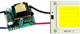
The converter must provide a current at which the LEDs will operate at the same brightness. The PT4115 LED driver circuit is implemented quite simply - it is the most common voltage converter for use with LED elements. You can literally make a device based on it “on your knees.”
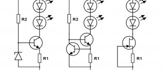
Stabilizer on PT4115
PT4115 is a unified chip developed by PowTech specifically for building drivers for high-power LEDs, which can also be used in cars. A typical PT4115 connection circuit and the formula for calculating the output current are shown in the figure below.
You can understand why this happens, as well as get acquainted with a more detailed calculation and selection of the remaining elements of the circuit here. The microcircuit gained fame due to its versatility and a minimal set of parts in the harness. To light an LED with a power from 1 to 10 W, the car enthusiast only needs to calculate the resistor and select the inductance from the standard list.
The PT4115 has a DIM input that greatly expands its capabilities. In the simplest version, when you just need to light the LED at a given brightness, it is not used. But if it is necessary to adjust the brightness of the LED, then either the signal from the output of the frequency converter or the voltage from the output of the potentiometer is supplied to the DIM input. There are options for setting a specific potential at the DIM pin using a MOSFET. In this case, when power is applied, the LED glows at full brightness, and when the MOSFET starts up, the LED dims the brightness by half.
The disadvantages of an LED driver for cars based on PT4115 include the difficulty of selecting the current-setting resistor Rs due to its very low resistance. The service life of the LED directly depends on the accuracy of its rating.
Both microcircuits discussed have proven themselves to be excellent in constructing drivers for LEDs in a car with your own hands. LM317 is a long-known, proven linear stabilizer, the reliability of which is beyond doubt. A driver based on it is suitable for organizing interior and dashboard lighting, turns and other elements of LED tuning in a car.
PT4115 is a newer integrated stabilizer with a powerful MOSFET transistor at the output, high efficiency and dimming capability.
Driver power.
The power of the device is the most important characteristic. The more powerful the driver, the greater the number of LEDs that can be connected to it (of course, you will have to carry out simple calculations). A prerequisite is that the driver power must be greater than that of all LEDs in total. This is expressed by the following formula:
Р = Р(св) x N,
where P, W – driver power;
P(sv), W – power of one LED;
N – number of LEDs.
For example, when assembling a driver circuit for a 10W LED, you can safely connect LED elements with a power of up to 10 W as a load. You definitely need to have a small power reserve - about 25%. Therefore, if you plan to connect a 10 W LED, the driver must provide a power of at least 12.5-13 W.
LED colors.
Be sure to take into account what color the LED emits. This determines what voltage drop they will have at the same current strength. For example, with a supply current of 0.35 A, the voltage drop for the red LED elements is approximately 1.9-2.4 V. The average power is 0.75 W. A similar model with green color will already have a drop in the range of 3.3-3.9 V, and a power of 1.25 W. Therefore, if you use a 220V LED driver circuit with conversion to 12V, you can connect a maximum of 9 elements with green color or 16 with red color to it.
Key type voltage stabilizers
This kind of 12V switching voltage regulator has an efficiency of 60%. The main problem is that it is not able to cope with electromagnetic interference. In this case, devices with a power of more than 10 W are at risk. Modern models of these stabilizers can boast a maximum voltage of 12 V. The load on the resistors is significantly reduced. Thus, on the way to the capacitor, the voltage can be completely converted. The current frequency is directly generated at the output. The wear on the capacitor in this case is minimal.
Another problem is related to the use of simple capacitors. In fact, they performed quite poorly. The whole problem lies precisely in the high-frequency emissions that occur in the network. To solve this problem, manufacturers began to install electrolytic-type capacitors on the pulse voltage stabilizer (12 volts). As a result, the quality of work was improved by increasing the capacity of the device.
Driver types.
In total, there are two types of drivers for LEDs:
- Pulse. With the help of such devices, high-frequency pulses are created in the output part of the device. Operation is based on the principles of PWM modulation. The average current value depends on the duty cycle (the ratio of the duration of one pulse to the frequency of its repetition). The output current changes due to the fact that the duty cycle fluctuates in the range of 10-80%, and the frequency remains constant.
- Linear - a typical circuit and structure are made in the form of a current generator using transistors with a p-channel. With their help, you can ensure the smoothest possible stabilization of the supply current if the input voltage is unstable. They are cheap, but have low efficiency. During operation, a large amount of heat is generated, so it can only be used for low-power LEDs.
Pulse ones have become more widespread, since their efficiency is much higher (can reach 95%). The devices are compact and the input voltage range is quite wide. But there is one big drawback - the high influence of various types of electromagnetic interference.
Step-up and step-down stabilizers
A boost regulator converts a low input voltage to a higher output voltage. This option is used for LEDs with a low-volt power supply (for example, in a car, you may need to increase the 12 volts for LEDs to 19 V or 45 V). Buck stabilizers, on the contrary, reduce high voltage to the desired level. All modules are divided into universal and specialized. Universal ones are usually equipped with two variable resistances - to obtain the required current and voltage parameters at the output. For specialized devices, the output values are most often fixed.
A special current stabilizer is used as a stabilizer for LEDs, circuit diagrams of which can be found in large quantities on the Internet. A popular model here is the Lm2596. LEDs are often connected to the car's power supply or battery via a resistor. In this case, the voltage can fluctuate in pulses up to 30 volts, which is why low-quality LEDs can fail (flashing running lights with partially inoperative LEDs). Current stabilization in this case can be carried out using a miniature converter.
How to make a driver for LEDs.
The circuits below use the most common elements that can be purchased at any radio store. No special equipment is required during assembly; all necessary tools are widely available. Despite this, with a careful approach, the devices work for quite a long time and are not much inferior to commercial samples.
Necessary materials and tools.
In order to assemble a homemade driver, you will need:
- Soldering iron with a power of 25-40 W. You can use more power, but this increases the risk of overheating of the elements and their failure. It is best to use a soldering iron with a ceramic heater and a non-burning tip, because... a regular copper tip oxidizes quite quickly and has to be cleaned.
- Flux for soldering (rosin, glycerin, FKET, etc.). It is advisable to use a neutral flux - unlike active fluxes (phosphoric and hydrochloric acids, zinc chloride, etc.), it does not oxidize the contacts over time and is less toxic. Regardless of the flux used, after assembling the device, it is better to wash it with alcohol. For active fluxes this procedure is mandatory, for neutral ones - to a lesser extent.
- Solder. The most common is low-melting tin-lead solder POS-61. Lead-free solders are less harmful when inhaling fumes during soldering, but have a higher melting point with lower fluidity and a tendency to degrade the weld over time.
- Small pliers for bending leads.
- Wire cutters or side cutters for cutting long ends of leads and wires.
- Installation wires are insulated. Stranded copper wires with a cross-section of 0.35 to 1 mm2 are best suited.
- Multimeter for monitoring voltage at nodal points.
- Electrical tape or heat shrink tubing.
- A small prototype board made of fiberglass. A board measuring 60x40 mm will be sufficient.
PCB breadboard for quick installation.
Types of drivers.
By type they can be divided into:
Linear. They are most suitable if the input voltage is not stable. Features improved stabilization. Rarely distributed due to low efficiency. Generates more heat, suitable for low-power loads.
Driver internals
Appearance and circuit diagram of the LED 1338G7 driver.
Pulse. Based on PWM chips. They have high efficiency. They are characterized by low heating and long service life.
Recom PWM driver.
PWM chips create significant levels of electromagnetic interference. People with pacemakers are not recommended to stay in rooms where such drivers are used to power LEDs.
Driver working with dimmer. The principle is based on the use of a PWM controller. The principle is that the current on the LEDs is regulated. Low quality products give a shimmering effect.
Driver with dimmer.
Electronic view of the device.
Ideally, the electronic converter should be equipped with a transistor. Its role is to unload the control microcircuit. To eliminate or smooth out ripple as much as possible, a capacitor is mounted at the output.
This type of device belongs to the expensive category, but it is capable of stabilizing current up to 750 mA, which ballast mechanisms are not capable of.
The newest drivers are mainly installed on light bulbs with an E27 socket. An exception to the rule is Gauss GU5.3 products. They are equipped with a transformerless converter. However, the degree of pulsation in them reaches several hundred Hz
Pulsation is not the only drawback of converters. The second can be called electromagnetic interference in the high frequency (HF) range. So, if other electrical appliances are connected to the socket connected to the lamp, for example, a radio, you can expect interference when receiving digital FM frequencies, television, router, etc.
The optional device of a quality device must have two capacitors: one is electrolytic to smooth out ripples, the other is ceramic to reduce RF. However, such a combination can be found rarely, especially when talking about Chinese products.
Those who have general concepts in such electrical circuits can independently select the output parameters of the electronic converter by changing the value of the resistors
Due to their high efficiency (up to 95%), such mechanisms are suitable for powerful devices used in various fields, for example, for car tuning, street lighting, and household LED sources.
Power supply based on capacitors.
Now let's move on to less popular devices - those based on capacitors. Almost all low-cost LED lamp circuits that use this type of driver have similar characteristics.
However, due to modifications by the manufacturer, they undergo changes, for example, the removal of some circuit element. Especially often this part is one of the capacitors - a smoothing one.
Due to the uncontrolled filling of the market with cheap and low-quality goods, users can “feel” one hundred percent pulsation in the lamps. Even without delving into their design, we can say that the smoothing element has been removed from the circuit
Such mechanisms have only two advantages: they are available for self-assembly, and their efficiency is equal to one hundred percent, since losses will only occur at pn junctions and resistances.
There are the same number of negative aspects: low electrical safety and high degree of pulsation. The second disadvantage is around 100 Hz and is formed as a result of rectification of the alternating voltage. GOST specifies a norm of permissible pulsation of 10-20%, depending on the purpose of the room where the lighting device is installed.
The only way to mitigate this drawback is to select a capacitor with the correct rating. However, you should not count on completely eliminating the problem - such a solution can only smooth out the intensity of the bursts.
Dimmable current converters.
Drivers-dimmers for dimmable LED bulbs allow you to change the incoming and outgoing current indicators, while reducing or increasing the brightness of the light emitted by the diodes.
There are two connection methods:
- the first involves a soft start;
- the second is impulse.
Consider the operating principle of dimmable drivers based on the CPC9909 chip, used as a regulating device for LED circuits, including those with high brightness.
Diagram of standard connection of CPC9909 with 220 V power supply. According to the schematic instructions, it is possible to control one or more powerful consumers
During a soft start, the microcircuit with the driver ensures gradual switching on of the diodes with increasing brightness. This process involves two resistors connected to the LD pin, designed to perform the task of smooth dimming. This is how an important task is achieved – extending the service life of LED elements.
The same output also provides analog regulation - the 2.2 kOhm resistor is replaced with a more powerful variable analogue - 5.1 kOhm. In this way, a smooth change in output potential is achieved.
The second method involves supplying rectangular pulses to the low-frequency output of the PWMD. In this case, either a microcontroller or a pulse generator is used, which are necessarily separated by an optocoupler.
With or without housing?
Drivers are available with or without a housing. The first option is the most common and more expensive. Such devices are protected from moisture and dust particles.
Devices of the second type are used for hidden installation and, accordingly, are inexpensive.
All presented devices can be powered from a 12 V or 220 V network. Despite the fact that open-frame models benefit in price, they lag significantly behind in terms of safety and reliability of the mechanism
Each of them differs in the permissible temperature during operation - this must also be taken into account when selecting.
Review of famous models
Most microcircuits for powering LEDs are made in the form of pulse voltage converters. Converters in which the role of an electrical energy storage device is played by an inductor (choke) are called boosters. In boosters, voltage conversion occurs due to the phenomenon of self-induction. One of the typical booster circuits is shown in the figure.
The current stabilizer circuit works as follows. A transistor switch located inside the microcircuit periodically closes the inductor to the common wire. At the moment the switch opens, a self-induction EMF arises in the inductor, which is rectified by a diode. It is characteristic that the self-induction EMF can significantly exceed the voltage of the power source.
As you can see from the diagram, very few components are required to make a booster on the TPS61160 manufactured by Texas Instruments. The main attachments are inductor L1, Schottky diode D1, which rectifies the pulse voltage at the output of the converter, and Rset.
The resistor performs two functions. Firstly, the resistor limits the current flowing through the LEDs, and secondly, the resistor serves as a feedback element (a kind of sensor). The measuring voltage is removed from it, and the internal circuits of the chip stabilize the current flowing through the LED at a given level. By changing the resistor value you can change the current of the LEDs.
The TPS61160 converter operates at a frequency of 1.2 MHz, the maximum output current can be 1.2 A. Using the microcircuit, you can power up to ten LEDs connected in series
The brightness of the LEDs can be changed by applying a variable duty cycle PWM signal to the “brightness control” input. The efficiency of the above circuit is about 80%. It should be noted that boosters are usually used when the LED voltage is higher than the power supply voltage
In cases where it is necessary to reduce the voltage, linear stabilizers are often used. A whole line of such MAX16xxx stabilizers is offered by MAXIM. A typical connection circuit and internal structure of such microcircuits is shown in the figure.
It should be noted that boosters are usually used when the voltage across the LEDs is higher than the voltage of the power supply. In cases where it is necessary to reduce the voltage, linear stabilizers are often used. A whole line of such MAX16xxx stabilizers is offered by MAXIM. A typical connection diagram and internal structure of such microcircuits is shown in the figure.
As can be seen from the block diagram, the LED current is stabilized by a P-channel field-effect transistor. The error voltage is removed from the resistor Rsens and supplied to the field control circuit. Since the field-effect transistor operates in linear mode, the efficiency of such circuits is noticeably lower than that of pulse converter circuits.
The MAX16xxx line of ICs are often used in automotive applications. The maximum input voltage of the chips is 40 V, output current is 350 mA. They, like switching stabilizers, allow PWM dimming.
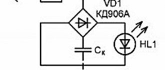
Classic driver circuit.
To independently assemble an LED power supply, we will deal with the simplest pulse-type device that does not have galvanic isolation. The main advantage of this type of circuit is simple connection and reliable operation.
The 220 V converter circuit is presented as a switching power supply. During assembly, all electrical safety rules must be observed, since there are no limits on current output
The scheme of such a mechanism is composed of three main cascade areas:
- Capacitive voltage separator.
- Rectifier.
- Surge Protectors.
The first section is the resistance provided to alternating current on capacitor C1 with a resistor. The latter is required solely for self-charging of the inert element. It does not affect the operation of the circuit.
The nominal value of the resistor can be in the range of 100 kOhm-1 Mohm, with a power of 0.5-1 W. The capacitor must be electrolytic, and its effective amplitude voltage value is 400-500 V
When the generated half-wave voltage passes through the capacitor, current flows until the plates are fully charged. The smaller the capacity of the mechanism, the less time it will take to fully charge it.
For example, a device with a volume of 0.3-0.4 μF is charged during 1/10 of the half-wave period, i.e., only a tenth of the passing voltage will pass through this section.
The straightening process in this section is carried out according to the Graetz scheme. The diode bridge is selected based on the rated current and reverse voltage. In this case, the last value should not be less than 600 V
The second stage is an electrical device that converts (rectifies) alternating current into pulsating current. This process is called full-wave. Since one part of the half-wave has been smoothed by a capacitor, the output of this section will have a DC current of 20-25 V.
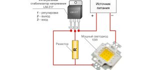
Since the LED power supply should not exceed 12 V, a stabilizing element must be used for the circuit. For this purpose, a capacitive filter is introduced. For example, you can use model L7812
The third stage operates on the basis of a smoothing stabilizing filter - an electrolytic capacitor. The choice of its capacitive parameters depends on the load strength.
Since the assembled circuit reproduces its operation immediately, you cannot touch the bare wires, since the conducted current reaches tens of amperes - the lines are first insulated.
Modified device models
The maximum load current of this type is perceived up to 4 A. The input voltage by the capacitor can be processed to a level of no more than 15 V. The input current parameter for them usually does not exceed 5 A. In this case, the ripple is allowed to be minimal with an amplitude in the network of no more than 50 mV. The frequency can be maintained at 4 Hz. All this will ultimately have a positive effect on the overall efficiency.
Modern models of stabilizers of the above type cope with a load of around 3 A. Another distinctive feature of this modification is the fast conversion process. This is largely due to the use of powerful transistors that operate with through current. As a result, it becomes possible to stabilize the output signal. A switching type diode is additionally used at the output. It is installed in the system near the voltage node. Heating losses are significantly reduced, and this is a clear advantage of stabilizers of this type.
Recommended LED Driver Manufacturers.
Many LED energy-saving lamps already have a built-in driver. However, it is better not to purchase nameless products from China. Although from time to time you come across specimens worthy of attention, which is otherwise a rare occurrence. There are a huge number of fake lights. Many models do not have galvanic isolation. This poses a danger to LEDs. If such current sources fail, they can give an impulse and burn the LED strip.
But nevertheless, the market is mainly occupied by Chinese products. Russian suppliers are not widely known. Of these, you can answer the products of the companies Argos, Triton LED, Arlight, Irbis, Rubicon. Most models can also work in extreme conditions.
Among foreign ones, you can safely choose current sources from Helvar, Mean Well, DEUS, Moons, EVADA Electronics.
Helvar LED driver.
Led driver Mean Well.
LED driver DEUS.
LED driver "Irbis".
LED driver MOSO.
Among the Chinese, you can trust MOSO. New brands may emerge that produce competitive devices.
Texas Instruments (USA) and Rubicon (Japan, not to be confused with Rubicon Russia. These are different brands) have good recommendations. But for now they are expensive.
Foreign and Russian analogues
What can replace lm317? Complete analogues of the microcircuit are GL317, SG317, UPC317, ECG1900. A very well-known domestic analogue of lm317t with a fixed voltage is the KP142EN12 microcircuit. If you need an adjustable linear stabilizer, then KREN12A is suitable (B is also possible).
Operational safety
The maximum voltage between input and output should not exceed 40 V. Dissipation power should not exceed 20 W. The soldering temperature should not exceed 260 °C, while maintaining a distance from the microcircuit body of more than 1.6 mm and a heating time of up to 10 seconds. The storage temperature of the device should be in the range from -65 to + 150 °C, operating temperature no more than + 150 °C.
These are maximum values that can damage the device or affect its stability. The microcircuit is well protected from thermal overload and contact short circuit. However, you should not exceed the permissible parameters during operation in order to avoid its failure and achieve maximum reliable operation.
220 V LED lamp driver circuit.
The current stabilizer in the case of an LED lamp is installed in the base of the device. And it is based on inexpensive microcircuits, for example, CPC9909. Such lamps must be equipped with a cooling system. They last much longer than any other, but it is better to give preference to trusted manufacturers, since the Chinese ones have noticeable hand soldering, asymmetry, lack of thermal paste and other shortcomings that reduce service life.
Driver circuit for LED lamp.
Diagram of connecting the driver to the LEDs.
Before connecting LEDs to the driver, you must be able to determine its polarity, in other words, recognize where the anode is (+) and where the cathode is (-). Without this there will be no light.
Indicator diodes, as well as some low-power lighting diodes, have two terminals.
LED terminals.
SMD (surface mount) LEDs have either 2 or 4 pins. In any case, this is the anode and cathode.
LED outputs in SMD version.
In the first case, pins 3 and 4 may not be used. In the second case, the oblique cut is located closer to the cathode. Please note that there is no single standard and polarity differences may occur.
Therefore, you can either refer to the datasheet, or use a low-voltage DC source and a limiting resistor. If the polarity is incorrect, the LED may not light up.
When using a current source, the driver circuit for the LEDs will be as follows:
LED connection diagram.
If we have a voltage source, then the connection is made through a limiting resistor.
Diagram for connecting an LED to a voltage source through a limiter.
The classic LED strip is built according to the following scheme:
LED line diagram.
In this case, the calculation is made using the formulas:
Formula for the relationship between current, voltage, resistance.
When connecting, it is important to consider:
- With low current, we lose in brightness, with high current, we lose service life.
- The voltage from the datasheet indicates the voltage drop when passing the rated current. This parameter is not the main one.
- Powerful LEDs require both high-quality power supply and good cooling.
Circuits (chips) of LED drivers.
As a rule, LED drivers are built on integrated stabilizers (KRENxx, or imported analogues) or PWM. The schemes are quite simple.
Using microcircuits for stabilization.
Schematic diagrams of LED drivers.
There is a circuit for a homemade current source based on the Soviet K142EN12A microcircuit. Resistor R2 allows you to change the brightness of the light.
Schematic diagram using domestic components.
Driver lifespan.
The service life of an ice driver for LED lamps depends on external conditions and the original quality of the device. The estimated service life of the driver is from 20 to 100 thousand hours.
The following factors can affect the service life:
- temperature changes;
- high humidity;
- power surges;
- incomplete load of the device (if the driver is designed for 100 W, but uses 50 W, the voltage returns back, which causes an overload).
Well-known manufacturers provide a warranty on drivers for an average of 30 thousand hours. But if the device was used incorrectly, the buyer is responsible. If the LED source does not turn on or has stopped working, the problem may be with the converter, an incorrect connection, or a malfunction of the lighting fixture itself.
Chinese drivers: is it worth saving?
Drivers are produced in China in huge quantities. They are low cost, so they are quite in demand. They have galvanic isolation. Their technical parameters are often overestimated, so it’s worth taking this into account when buying a cheap device.
Most often these are pulse converters, with a power of 350÷700 mA. They do not always have a housing, which is even convenient if the device is purchased for the purpose of experimentation or training.
Disadvantages of Chinese products:
- simple and cheap microcircuits are used as the basis;
- devices do not have protection against power fluctuations and overheating;
- create radio interference;
- create high-level ripple at the output;
- They do not last long and are not guaranteed.
Not all Chinese drivers are bad; more reliable devices are also produced, for example, based on PT4115. They can be used to connect household LED sources, flashlights, and strips.
Manufacturing instructions
Overheating may damage the inductor connector.
An electric oven with a capacity of 65 liters is provided.
Experts have proven that at a distance of 2 cm from the stove, radiation is always higher than the permissible norm. Its features include a glass-ceramic surface, touch controls, and the ability to control power. The universal alternator board operates exclusively at high frequency.
Whirlpool Experienced housewives prefer Whirlpool products. Batteries should be combined in sections of 2 pieces. The burner will not turn on if there is a frying pan or pan with a non-magnetic bottom on the stove; Automatic shutdown when removing dishes; Maintaining the set temperature at a certain level.
More on the topic: Connecting 2 key switches
Miracles of induction
According to the owner of the stove, it became clear that the stove simply turned off during cooking and showed no signs of life. The design of an induction cooker is based on the fact that after placing the pan on the work surface, currents come into action, which carry out heating. No spam, only useful ideas!
Firstly, it turned out that they absolutely did not know what an induction cooker was, mistaking it for an infrared cooker. Perhaps in 10 years you will change it to a more powerful model and you will need a cross section of 2.5 mm2. Results - the pros and cons of induction cookers An induction cooker is a reliable assistant in the kitchen, which compares favorably with classic gas or electric ovens.
To avoid losing the article, like it!
A mechanic's kit for learning how an induction cooker works. I've heard about such things, but I've never personally used them. Do you need such a device in the kitchen, a question for professionals, judging by the advertisement, cooking on this stove occurs without the release of excess heat, since the hob does not heat up. But in a single-phase network, this is usually not enough to reliably connect an induction hob - it is better to use screw terminals. This completes the renovation.
Color: satin bronze. I've heard about such things, but I've never personally used them. Under the glass-ceramic surface of the stove there is an induction coil through which an electric current flows with a frequency of about 50 kHz. Induction cooker repair
Dimmable current converters for LEDs.
Dimming is the regulation of the intensity of light emanating from a lighting fixture. Dimmable drivers for LED lamps allow you to change the input and output current parameters. Due to this, the brightness of the LEDs increases or decreases. When using regulation, it is possible to change the color of the glow. If the power is less, then the white elements may turn yellow, if more, then blue.
Dimming LEDs using the remote control
Pulse current stabilizers
More economical devices include current stabilizers, which are based on a pulse converter. This element is also known as a key converter or converter. Inside the converter, power is pumped in certain portions in the form of pulses, which determined its name. In a normally operating device, power consumption occurs continuously. It is continuously transmitted between the input and output circuits and is also continuously supplied to the load.
In electrical circuits, a current and voltage stabilizer based on pulse converters has almost the same operating principle. The only difference is that the current through the load is controlled instead of the voltage across the load. If the current in the load decreases, the stabilizer pumps up power. In case of increase, the power is reduced. This allows you to create current stabilizers for high-power LEDs.
The most common circuits additionally have a reactive element called a choke. Energy is supplied to it in certain portions from the input circuit, which is subsequently transferred to the load. Such transmission occurs through a switch or key, which is in two main states - off and on. In the first case, no current passes and no power is released.
In the second case, the key conducts current while having very low resistance. Therefore, the released power is also close to zero. Thus, energy transfer occurs with virtually no power loss. However, the pulse current is considered unstable and special filters are used to stabilize it.
Along with obvious advantages, the pulse converter has serious disadvantages, the elimination of which requires specific design and technical solutions. These devices are complex in design and create electromagnetic and electrical interference. They expend a certain amount of energy for their own work and, as a result, heat up. Their cost is significantly higher than that of linear stabilizers and transformer devices.
However, most of the shortcomings are successfully overcome, which is why switching stabilizers are widely popular among consumers.
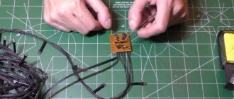
How to make a driver for LEDs with your own hands.
The device can be made from any unnecessary phone charger. It is necessary to make only minimal improvements and the microcircuit can be connected to LEDs. It is enough to power 3 1 W elements. To connect a more powerful source, you can use boards from fluorescent lamps.
Important! During work it is necessary to observe safety precautions. Touching exposed parts may result in an electric shock of up to 400 V.
| Photo | Stage of assembling the driver from the charger |
| Remove the housing from the charger. | |
| Using a soldering iron, remove the resistor that limits the voltage supplied to the phone. | |
| Install a tuning resistor in its place until it needs to be set to 5 kOhm. | |
| Using a serial connection, solder the LEDs to the output channel of the device. | |
| Remove the input channels with a soldering iron, and in their place solder a power cord to connect to a 220 V network. | |
| Check the operation of the circuit, set the regulator on the trimming resistor to the required voltage so that the LEDs shine brightly but do not change color. |
Example of a driver circuit for LEDs from a 220 V network
Which microcircuit should I choose?
If you don’t want to look for a ready-made device, you can make it yourself. Moreover, make calculations for specific LEDs. There are quite a lot of microcircuits for making drivers. All you need is the ability to read electrical diagrams and use a soldering iron. For the simplest devices (power up to 3 W), you can use the PT4115 chip. It's cheap and very easy to get. The characteristics of the element are:
- Supply voltage – 6-30 V.
- Output current – 1.2 A.
- The permissible error when stabilizing the current is no more than 5%.
- Load cut-off protection.
- Conclusions for dimming.
- Efficiency – 97%.
Designation of microcircuit pins:
- SW – connection of the output switch.
- GND – negative terminal of power and signal sources.
- DIM – brightness control.
- CSN – input current sensor.
- VIN is the positive terminal connected to the power supply.
LED driver lifespan.
There is no specific service life as such, but many manufacturers are willing to provide a five-year warranty on their products. Naturally, upon coordination of capacities. In order for the power source to last longer, you should not provide a load at which it will deliver maximum currents. If it is assembled from high-quality components, it will work stably for quite a long time. But operating temperatures can be close to critical (depending on circuit design solutions). It is optimal if the power of consumers is 20-30 percent less.
If we are talking about homemade production, then a lot depends on the quality of the assembly and the quality of the radio components. It is advisable to attach integral stabilizers to a radiator to ensure thermal conditions; do not forget about the heat-conducting paste between the stabilizer body and the heat sink.