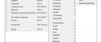
1Download Arduino IDE
Download the Arduino development environment (Arduino IDE) from the official website for your operating system (Windows, Mac OS X, Linux are supported). You can select the installer ( Installer ), you can choose the archive ( ZIP file for non admin install ). In the second case, the program is simply launched from the folder, without installation. The downloaded file contains, in addition to the development environment, drivers for boards of the Arduino family.
Download the Arduino IDE from the official website
Arduino for beginners - starter kit or how to start Arduino? Lots of photos and videos!
Probably, many have heard about such a wonderful platform, but due to poor knowledge of electronics or programming, many will decide to bypass arduino. Yes, the platform is quite complex, but you can figure it out, the main thing is desire. For a long time I myself did not dare to study this platform, but one fine day I realized that it could make my life easier... There is a lot of information about arduino on the Internet, but without practice, no theory will help, so I decided to buy this kit, but I’ll get ahead of myself that it’s still cheaper to buy all the components yourself, not as a kit, and I’ve posted archives with instructions and programs (sketches) below. Why did I take this set, because there is a lot of choice in China? Previously, Arduino was like something transcendental and incomprehensible to me, and I chose it only because of the number of lessons, which is why I chose this set, by the way, a similar set was already reviewed by drawde. I bought it directly from Tao: The set came in a plastic case sealed with tape, apparently so that nothing would be taken out of the box (I had already torn the tape):
What's in the box?
Equipment:
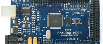
— 1x arduino uno board, maybe even the original — 1x LCD display 16 characters on 2 lines with i2c board
— 15x LEDs: 5 pcs. red, 5 pcs. blue and 5 pcs. orange - 3x photoresistor - 1x IR receiver - 1x flame sensor - 2x vibration sensor - 1x temperature sensor - 4x buttons - 2x piezoelectric elements
— digital LED display for 1 digit — digital LED display for 4 digits — LED matrix 8x8
— 8x constant resistor at 220 Ohm — 5x constant resistor at 1 kOhm — 5x constant resistor at 10 kOhm — 1x variable resistance resistor (potentiometer) at 50 kOhm
— 1x large mock-up platform
— 1x DuPont cable female-male 30 multi-colored wires
— 30 connecting wires for the prototyping platform, male-male
— 1x USB cable
— 1x RFID board — 1x RFID card — 1x RFID for keys
— 1x IR remote control — 1x microphone module — 1x 4x4 button pad model — 1x relay — 1x clock module — 1x driver module for motor — 1x temperature and humidity sensor module — 1x joystick module — 1x RGB LED module — 1x humidity sensor module — 1x power cable for crown
— 1x servo drive — 1x motor with gearbox — 1x shift register 74НС595N This is what everything looks like assembled:
When I received the set, I immediately started looking for instructions, but I didn’t find anything inside the box, I thought that the Chinese had deceived me and was about to argue with him, but I read the description of the lot and there was a link with all the instructions and programs: yunpan.cn/cFWkif3FY3cgk ( password:22cd) But it’s better not to use Chinese programs, so it’s better to download the arduino programming program from the official website: arduino.cc/en/Main/Software And here I have collected instructions, programs, sketches found on the Internet and my sketches, which useful in mastering arduino.
Start
I recommend that you first read the pdf book in Russian: Guide to Mastering Arduino - 2012, which is on my assembly. There is a lot of useful information written there in clear language, but there are only a few lessons. Modkit_Desktop_WIN32_Kickstarter_v2.zip
archive contains a program for visual programming.
The Arduino archive - chinese.rar
contains Chinese instructions, Chinese sketches, libraries, but there are many errors there.
The Arduino archive - program.rar
contains an arduino program with libraries that were useful to me in mastering arduino.
in the arduino-master
. There are quite a lot of lessons, diagrams, libraries with good descriptions in English.
Moreover, most of this archive was “pulled” by the Chinese. In the archive My sketches.rar
there are my projects, although there are 34 of them, I did not complete all the Chinese lessons, I corrected some and I did the most recent project myself.
The numbers of my sketches do not match the numbers of the lessons being reviewed, but all my sketches are signed in transliteration and I think everyone will understand. Begin!
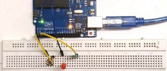
Lesson #1 - LED flashing
For this lesson we will need the following details:
- 2 wires (I will not indicate the number of wires further), - LED, - 220 Ohm resistor, - breadboard and arduino uno board.
Connect:
And we get:
Lesson #2 - connecting 8 LEDs - running lights
For this lesson you need:
- 8 LEDs, - 8 220 Ohm resistors, - wires, breadboard and arduino. I connected it a little incorrectly, put 1 resistor to ground and connected it to all the LEDs:
Result:
Lesson #3 - changing LED brightness using a variable resistor
We need:
- LED, - variable resistor, - 220 Ohm resistor, - wires, breadboard and arduino
This time I decided not to connect a resistor to the LED, but if you connect it “permanently”, then you need to put a resistor on the LED, otherwise the LED will burn out quickly.
Result:
Lesson No. 4 - running lights made of 6 LEDs
Required:
- 6 LEDs, - 220 Ohm resistor - wires, breadboard and arduino
It turned out like this:
Result:
Lesson No. 5 - connecting an RGB LED
You will need:
- RGB module - wires, breadboard and arduino
It turned out like this:
Result:
Lesson No. 6 - connecting the piezoelectric element
Details:
- piezoelectric element - wires, breadboard and arduino
It turned out like this:
Result:
With music:
Lesson No. 8 - turning on the LED from the button
Details: - button - LED - 220 Ohm and 10 kOhm resistors - wires, breadboard and arduino It turned out like this:
Result:
Lesson No. 8.1 - on/off. LED from the button
Details:
- LED - 2 buttons - 220 Ohm resistor - 2 10k Ohm resistors - wires, breadboard and arduino
It turned out like this
Result:
Lesson No. 8.2 - changing the brightness of the LED from the button
The connection diagram is identical to lesson 8.1, only the sketch is different and the result is:
Lesson #9 - servo drive
Details:
- servo drive - wires, breadboard and arduino
It turned out like this: Result:
Lesson #10 - Connecting the 74HC595 Shift Register
Parts:
- 8 LEDs - 74HC595 shift register - 8 220 ohm resistors - wires, breadboard and arduino
It turned out like this:
Lesson No. 11 - changing the brightness of an LED using a photoresistor
Details:
- photoresistor - LED - 220 Ohm and 10 kOhm resistor - wires, breadboard and arduino
It turned out like this:
Result:
Lesson #12 - voltmeter
Details:
- battery - 10 kOhm resistor - wires, breadboard and arduino
It turned out like this:
The result is displayed in the “protra monitor”:
Lesson #13 - Temperature Measurement
Details:
- temperature sensor - wires, breadboard and arduino
It turned out like this: The result is displayed in the “protra monitor”:
If you heat the sensor with a lighter, the temperature changes:
Lesson #13.1 - temperature change - visual display
Details:
- temperature sensor - 3 LEDs - 220 Ohm resistor - wires, breadboard and arduino
It turned out like this: Result:
Lesson #14 - Connecting a Digital LED Display
Details:
- 6 220 Ohm resistors - digital LED display - wires, breadboard and arduino
It turned out like this:
Result of the Chinese sketch:
Result of my revised sketch:
Lesson #14 - connecting a 4-digit LED digital display
Details:
- LED panel with 4 digits - wires, breadboard and arduino
It turned out like this:
The result is a stopwatch:
Lesson No. 15 - connecting an 8x8 LED matrix
Details:
- 8x8 LED matrix - wires and arduino
It turned out like this:
The result of my sketch:
Lesson No. 16 - connecting a humidity sensor
Details:
- humidity sensor - LED (I connected the RGB module to 1 LED) - wires and arduino
It turned out like this:
Result:
Lesson #17 - Measuring Temperature and Humidity
Details:
— humidity and temperature sensor — wires and arduino
It turned out like this: The result is displayed in the “protra monitor”:
Lesson #18 - connecting the relay module
Details:
- relay module - LED - 220 Ohm resistor - wires, breadboard and arduino
It turned out like this: Result:
Lesson No. 19 - connecting a 16x2 LCD display
Details:
- LCD1602 display - wires and arduino
It turned out like this: Result:
Lesson #20 - connecting the motor
Details:
- driver module for the motor - motor with gearbox - wires and arduino
It turned out like this:
Result:
Lesson #21 - Turning LEDs on/off using the remote control
Details:
- IR remote control - IR receiver - 6 LEDs - 6 220 Ohm resistors - wires, breadboard and arduino
It turned out like this:
Result:
Lesson #22 - Connecting a joystick
Details:
- joystick - wires and arduino
The result is displayed in the “protra monitor”:
Lesson #23 - Connecting a 4x4 keyboard
Details:
- keyboard - wires and arduino
The result is displayed in the “protra monitor”:
Lesson #24 - RFID Connection
Details:
— RFID module — wires and arduino
It turned out like this: The result is displayed in the “protra monitor” — reading the card dump: The result is displayed in the “protra monitor” — reading the key fob:
The result is displayed in the “protra monitor” - I tried to read the UEC, a bank card with payWave and a transport card:
I only got 24 lessons; I didn’t cover the rest in the review, although I collected and checked them myself; it seemed to me that they were not interesting to review.
To consolidate the result, I decided to assemble a digital thermometer and write a program, although at first I wanted to assemble a humidity and temperature meter, but due to an incorrect connection, I “killed” this module, so I only had to do a temperature measurement.
Homework - digital thermometer
Details:
- temperature sensor - LCD display - wires, breadboard and arduino
It turned out like this:
The most difficult thing left is to combine 2 sketches and to make it all work, we get this sketch: Digital thermometer
#include #include LiquidCrystal_I2C lcd(0x27,16,2); int potPin = 0; // pin where the sensor is connected float dat = 0; // variable for temperature void setup() { lcd.init(); lcd.backlight(); lcd.begin(16, 2); lcd.print("S"); delay(300); lcd.print("p"); delay(300); lcd.print("e"); delay(300); lcd.print("c"); delay(300); lcd.print("i"); delay(300); lcd.print("a"); delay(300); lcd.print("l"); delay(300); lcd.print("l"); delay(300); // wait 0.5 seconds lcd.print("y"); delay(300); // wait 0.5 seconds lcd.print("f"); delay(300); // wait 1 second lcd.print("o"); delay(300); // wait 1 second lcd.print("r"); delay(700); lcd.setCursor(0, 1); lcd.print("h"); delay(300); lcd.print("t"); delay(300); lcd.print("t"); delay(300); lcd.print("p"); delay(300); lcd.print(":"); delay(300); lcd.print("/"); delay(300); lcd.print("/"); delay(300); lcd.print("m"); delay(300); lcd.print("y"); delay(300); lcd.print("s"); delay(300); lcd.print("k"); delay(300); lcd.print("u"); delay(300); lcd.print("."); delay(300); lcd.print("r"); delay(300); lcd.print("u"); delay(300); lcd.clear(); //clear the screen delay(1000); lcd.setCursor(0, 0); lcd.print("Specially for"); lcd.setCursor(0, 1); lcd.print("https://mysku.ru"); delay(500); lcd.clear(); //clear the screen delay(300); lcd.setCursor(0, 0); lcd.print("Specially for"); lcd.setCursor(0, 1); lcd.print("https://mysku.ru"); delay(500); lcd.clear(); //clear the screen delay(300); lcd.setCursor(0, 0); lcd.print("Specially for"); lcd.setCursor(0, 1); lcd.print("https://mysku.ru"); delay(500); lcd.clear(); } void loop() { lcd.init(); // initialize the lcd lcd.clear(); // clear the screen // read and calculate the temperature dat = ( 5.0 * analogRead(potPin) * 100.0) / 1024.0; lcd.backlight(); lcd.setCursor(0, 0); // place the cursor in the 0th // column, 1st line (starts at 0) lcd.print("Temperatura"); lcd.setCursor(0, 1); lcd.print(" "); lcd.print(dat); // display the current temperature lcd.print("'C"); delay(5*500); // delay before repeating measurements }
I had a little peek here.
Result:
Now you need to check the error:
As you can see, the error is very small, although it is possible that the weather station and my design both thermometers are lying.
Why did I start all this?
I want to automate brewing, while this is still a distant project.
+
There are many of them, with the help of arduino you can create many projects for almost any purpose. There are plenty of instructions on the Internet. With this kit you can easily learn arduino - instructions to help.
—
The price seems too high to me. There are a lot of errors in the Chinese instructions, for example, a lesson from one project, a sketch from a completely different one, and a diagram from a third
Conclusion:
I liked Arduino, I will try to invent something more interesting and complex, and I recommend that all beginners buy Arduino not as a set, but as separate modules.
That's all, I hope my review didn't seem too boring.
Thank you for your attention!
3Installing the driver for Arduino
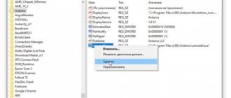
Install the driver for Arduino. Consider the installation option on the Windows operating system. To do this, wait until the operating system prompts you to install the driver. Decline. Press the Win + Pause , launch Device Manager . Find the section "Ports (COM and LPT)" . You will see a port there called Arduino UNO (COMxx) . Right-click on it and select Update Driver . Tell the operating system the location of the driver. It is located in the drivers in the folder we just downloaded.
Note the port to which the Arduino board is connected. To find out the port number, launch Device Manager and look for the “Ports (COM and LPT)” section. The port number will be indicated in parentheses after the board name. If the board is not in the list, try disconnecting it from the computer and waiting a few seconds, then connecting it again.
Arduino in Windows Device Manager
First steps
When you first think about which Arduino nano projects for beginners to choose at the start, the first thing you should do is:
- Purchase all relevant consumables. In addition to boards and modules, these also include platforms, rosin and copper plates if you plan to design the motherboard yourself.
- Find as detailed a manual as possible for your project and try to understand what they do there, and not just copy it. You will find more different interesting projects and instructions in our Lessons section.
- Modify your project. Good systems are scalable, meaning you can add some functionality to them, and they will continue to be comfortable to use and manage the code.
4Setting up Arduino IDE
Point your development environment to your board. select Arduino UNO from the Tools Board .
Select the Arduino UNO board in the settings
Specify the number of the COM port to which the Arduino board is connected: Tools Port.
Set the serial port to which the Arduino board is connected
7Loading sketches into Arduino memory
Now you can load the program into the board's memory. Connect the board to the computer, wait a few seconds while the board initializes. Click the Upload , and your sketch will be written to the memory of the Arduino board.
The LED should start blinking cheerfully at you every 2 seconds (1 second on, 1 second off). Below is the code for our first Arduino program. void setup() {
// initialization block pinMode(13, OUTPUT);
// set pin 13 as output. } void loop() {
// loop that repeats endlessly as long as the board is turned on: digitalWrite(13, HIGH);
// apply a high level to pin 13 - light the LED delay(1000); // for 1000 ms = 1 sec. digitalWrite(13, LOW); // apply a low level to pin 13 - turn off the LED delay(1000); // for 1 sec. }
// then the cycle repeats
Read the comments in the text of the program - they are enough to understand our first experiment. First we describe the initialization block setup()
, in which we set the initial values of the variables and the functions of the Arduino pins.
What follows is an endless loop()
that repeats over and over again as long as power is supplied to the board.
In this cycle we perform all the necessary actions. In this case, we turn on and turn off the LED. The delay()
operator specifies the execution duration (in milliseconds) of the preceding operator.
The digitalWrite()
statement tells the Arduino which pin to apply voltage to, and exactly what voltage level. Your first sketch is ready!
Helpful advice
There are many sites on the Internet dedicated to working with Arduino family boards. Read, master, don’t be afraid to experiment and learn new things! This is a fun and rewarding activity that will bring you a lot of pleasure.
Preparation and infinity
In any Arduino program there are two fundamental parts: the preparatory part and the main loop.
In the preparatory part, you tell the hardware what to expect from you: which ports to configure for input, which for output, what you call it. For example, if you have a sensor connected to input 10, and a light bulb to output 3, then you can call these inputs and outputs as you wish, and then in the code refer not to the tenth input and third output, but in a human way: to the sensor or light bulb. The entire preparation part is performed once when the controller starts. The controller remembers everything and goes into the main loop.
The main loop is what happens in the loop() function. Arduino takes commands from there and executes them in a row. As soon as the commands are finished, it returns to the beginning of the loop and repeats everything. And so on ad infinitum.
In the main loop we describe all the useful things that the controller should do: read data, blink lights, turn motors on and off, feed the cat, etc.