In electrical engineering, the need to switch electrical circuits often arises. Each electromechanical switching device has at least one pair of connecting contacts. Contrary to expectations, it is often possible to observe that the contacts heat up. The reason for this is the contact resistance of the contacts, which cannot be completely eliminated.
The contact spot is formed as a result of any contact of conductors. At the point of connection of the wires, a resistance always arises that exceeds the resistivity of the conductor materials. There are several reasons for this phenomenon, which will be discussed in this article. First, let’s find out what is meant by the term contact resistance.
Introduction
An electrical contact is one of the basic elements of any electrical circuit. Due to the increasing complexity of technical systems, the number and variety of types and forms of contacts, their modes and operating conditions are growing. The role of contacts becomes more responsible both in technical and technical-economic terms. All this requires a more intensive and in-depth study of physical processes in various modes and operating conditions of contacts, methods of engineering calculation and design, correct regulation of operating modes and conditions, development and research of new contact materials and new structural forms of contacts.
This article outlines the basic principles of operation, physical processes and phenomena occurring in electrical connectors, and identifies the basic concepts and their physical meaning. Factors that determine the reliability, durability and storage conditions of electrical connectors are given. Ways to increase reliability and durability are determined, and operating rules are outlined.
Quantum limit
When a conductor has spatial dimensions close to , where the Fermi wave vector of the conducting material is located, Ohm's law no longer holds. These small devices are called quantum dot junctions. Their conductivity must be an integer multiple of , where is the elementary charge and is Planck’s constant. Quantum point contacts behave more like waveguides than the classical wires of everyday life and can be described by the Landauer scattering formalism. Point-contact tunneling is an important method for characterizing superconductors. 2πkF{\displaystyle 2\pi /k_{\text{F))}kF{\displaystyle k_{\text{F))}2e2h{\displaystyle 2e^{2}/h}e{\displaystyle e} h{\displaystyle h}
Bolted contact connections.
Contact connections made using bolts most often have defects due to the lack of washers at the junction of the copper core with a flat terminal made of copper or aluminum alloy, the absence of disc springs, direct connection of the aluminum tip to the copper terminals of equipment in rooms with an aggressive or humid environment , as a result of insufficient tightening of bolts, etc. Bolted contact connections of aluminum busbars for high currents (3000 A and above) are not stable enough in operation. If contact connections for currents up to 1500 A require tightening the bolts once every 1 - 2 years, then similar connections for currents of 3000 A and above require annual overhaul with the obligatory cleaning of the contact surfaces. The need for such an operation is due to the fact that in high-ampere busbars (busbars of power plants, etc.) made of aluminum, the process of formation of oxide films on the surface of contact joints occurs more intensively. The process of formation of oxide films on the surface of bolted contact joints is facilitated by different temperature coefficients of linear expansion of steel bolts and aluminum busbars. Therefore, when a short-circuit current passes through the busbar, when it operates with an alternating current load, deformation (compaction) of the contact surface of the aluminum bus occurs in it over a long distance as a result of vibration influences. In this case, the force tightening the two contact surfaces of the busbar weakens, the lubricant layer between them evaporates, etc. Due to the formation of oxide films, the contact area of the contacts, i.e. the number and size of contact pads (number of points) through which current passes decrease and, at the same time, the current density increases, which can reach thousands of amperes per square centimeter, as a result of which the heating of these points increases greatly. The temperature of the last point reaches the melting temperature of the contact material, and a drop of liquid metal forms between the contact surfaces. The temperature of the drop, rising, reaches a boil, the space around the contact connection is ionized, and there is a danger of a multiphase short circuit in the switchgear. Under the influence of magnetic forces, the arc can move along the switchgear busbars with all the ensuing consequences. Operating experience shows that, along with multi-ampere busbars, single-bolt contact connections also have insufficient reliability. The latter, in accordance with GOST 21242-75, are allowed for use at a rated current of up to 1,000 A, but are damaged already at currents of 400 - 630 A. Increasing the reliability of single-bolt contact connections requires taking a number of technical measures to stabilize their electrical resistance. The process of development of a defect in a bolted contact connection, as a rule, takes quite a long time and depends on a number of factors: load current, operating mode (stable load or variable), exposure to chemical reagents, wind loads, bolt tightening forces, contact pressure stabilization, etc. Transitional The resistance of a bolted contact connection depends on the duration of the current load. The contact resistance of contact connections gradually increases up to a certain point, after which a sharp deterioration of the contact surface of the contact connection occurs with intense heat generation, indicating an emergency condition of the contact connection. Similar results were obtained by specialists from Inframetrix (USA) during thermal tests of bolted contact joints. The increase in heating temperature during testing was gradual throughout the year, and then there was a period of sharp increase in heat release.
Main advantages of soldering
- no expensive equipment required;
- this connection is easy to repair - you just need to warm it up well with the same soldering iron;
- soldered wires can withstand heavy loads - they will not unwind, break or tear even under significant mechanical force.
It should be noted that soldering wires can be performed to connect almost any metal, both the same type and different ones. The main trick when soldering is to achieve the same temperature of both the surfaces being joined and the solder. It is if this condition is met that we will get an excellent result. To do this, you need to choose a good tool, solder and flux.
This means that thick twists are unlikely to be soldered well with a 40-watt soldering iron, especially if the room temperature is low. Good wire stripping is very important. We remove oxide from copper mechanically (by scraping), but with aluminum the situation is more complicated. Typically, the film is removed from aluminum wires during soldering by scraping it off under the layer of molten solder.
You can also use a special flux that corrodes the oxide when heated. The main thing is to remove excess flux residues after soldering so that the soldered joint does not subsequently collapse. To do this, you can use technical alcohol or Galosh gasoline.
The soldering area must be well insulated. You can use electrical tape for this - cotton (more heat-resistant) or vinyl (with good moisture resistance). The greatest airtightness can be achieved by laying fabric insulation inside and vinyl on the outside. Instead of electrical tape, you can use a protective plastic cap, which looks neater.
How to measure contact resistance correctly
There are certain rules that describe the correct measurement of Rn for switching devices. These include circuit breakers, all kinds of disconnectors and buses.
There are several measurement methods:
- a method when the counting is carried out directly and directly;
- using a multimeter (you can also use an ammeter or voltmeter);
- a method for measuring the unstable static behavior of a junction resistance.
Note! The first point involves the use of instruments for direct calculation with an error of less than 10%. It is most often used to measure Rn of a contact connection.
The contacts are not cleaned before measurement. They are connected to the terminals of the devices. At the same time, moving devices and opening contacts is contraindicated.
Formula for unstable static joint venture
In the second method, the magnitude of the voltage drop is determined at a fixed current value at the junction that is being tested. The error of any device in a measuring system of this kind is no more than 3%. Initially, the resistance value is selected several times greater than expected. The calculation is performed using the formula: Rп = UPV2/IPA, where UPV2 is the figure shown by the PV2 voltmeter in V; IPA is the current measured by the ammeter PA in Am.
The static instability of the junction resistance is determined based on the root mean square change in Rn determined through repeated measurements. The error of such measurements is +/- 10%.
List of devices for measuring SP
Standards according to PUE 7
The rules provide for compliance with important parameters, including acceptable values for contact transitions. DC resistance measurements are carried out when testing disconnectors and separators. The standards for PUE 7 require that the readings of values for separators and disconnectors designed to operate at voltages from 110 kV correspond to the manufacturer’s data.
According to the rules of PUE 7 for disconnectors of the RON3 type, designed for a rated voltage of 400 - 500 kV (at a rated current of 2000 A), the transition resistance should not exceed 200 μOhm. For OSR (110 – 220 kV/600 A, the contact resistance should be 220 μOhm.
Requirements for other types of separators used in networks 110 – 500 kV:
- A rated current of 600 A corresponds to a resistance of 175 μOhm;
- 1000 A – 120 µOhm;
- 1500 – 2000 A – the highest permissible resistance is 50 μOhm.
Measurements are made between the “contact input” point and the “contact output” terminal.
Contact surface
The contact surface, like any solid body, always has roughness and waviness. An approximately geometric model of the contact surface can be considered as a certain wavy surface on which spherical protrusions are located. The height of the protrusions relative to the base of the waves is not the same. The statistical distribution of the heights of these protrusions is close to normal.
The presence of roughness and waviness leads to the fact that the two surfaces always contact only in separate “spots”.
The surface, which is a collection of points through which pressure is transmitted, is called the effective mechanical contact surface, and if it is a pure metal, that is, its surface is free of non-conducting films, then such a surface will also be an effective electrical contact surface.
The effective contact surface is a function of contact pressure.
Under the action of pressing force, the two surfaces are brought closer together due to the deformation of the contacting protrusions, and more and more individual protrusions come into contact. The approach of the contacting surfaces occurs until the sum of the reactions of the elastically deformed protrusions is equal to the pressing force N, that is, when:
where nk is the number of contacting protrusions; Ni is the reaction of the protrusion deformed by the amount Δi.
The size of the effective contact surface is equal to:
where r is the average radius of the protrusions, the value of which is determined by the cleanliness of the contact surfaces.
The relationship between the effective contact surface and contact pressure can be represented as:
for the case of contact along a line (for example, contact between the generatrix of a cylinder and a plane).
for the case of contact along a plane, where E is Young’s modulus; hm—maximum height of protrusions; no is the total number of protrusions on the “apparent” contact surface.
At contact pressures of the order of 0.015-1.0 kgf, which usually occur in practice in detachable contacts, the effective contact surface is negligible compared to the apparent contact surface. Usually it ranges from fractions to units of percent.
Features of wear of contacts opened under current
The normal operating mode of the bulk of electrical connectors involves their opening and connection in a de-energized state. The exception is breakaway connectors and some other structures.
Sometimes it becomes necessary to open live electrical connectors. This is extremely undesirable, since this mode of operation sharply reduces the service life of the electrical connectors.
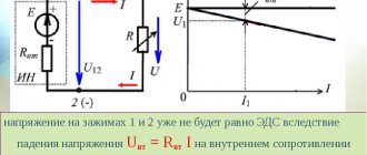
When the contacts are opened under current, there is a sharp increase in the transition resistance and voltage drop across them, which leads in accordance with the equation
to an increase in the temperature of the contacted protrusions, up to the melting temperature of the contact material. At the first moment of opening the contacts, a bridge is formed between them from the molten metal of the contact coating and the metal of the contacts themselves, which, with further divergence of the contacts, will thin out not in the middle, but closer to the positive electrode, where it will finally break. This phenomenon is similar to electrolysis. This process causes metal to transfer from one contact to another. This phenomenon is called bridging erosion of contacts.
When voltages and currents in the open circuit are less than certain values for specific contact materials (for example, for silver UI
As a result of erosion, the microgeometry of the contact surfaces changes, which leads to increased mechanical wear of the contact surfaces, since electrical erosion prevents the transition of the contact wear process from the running-in phase to the normal wear phase.
In the case when the voltage and current in the circuit being broken are greater than certain values (for example, for silver U > 12 V, I > 0.4 A), an electric arc occurs between the contacts when they open. The arc causes increased erosion of the contacts, both due to its thermal effect and due to the bombardment of the cathode by gas ions that are formed at the moment the arc burns. The mode of operation of electrical connectors with the formation of an electric arc between the contacts at the moment they open is extremely undesirable and must be excluded when operating electrical connectors. Even short-term operation of connectors in the electric arc formation mode practically reduces the resource of normal operation of the electrical connector to zero.
Factors that cause
Contact resistance connects individual sections of the circuit to each other. At the junction, a mutual contact of current conduction is formed. Through this section, current from one branch can enter another. If you simply put the wires on top of each other, there will be no reliable connection. This is due primarily to the fact that the surface, no matter how smooth it may seem, consists of irregularities. With multiple magnification, this can be seen even on perfectly ground and polished materials.
Important! In practice, it will become clear that the area of real contact is much smaller than the visual one. Another factor in the occurrence of junction resistance is the film resulting from the oxidation of the conductor metal
Such films prevent the current from moving and tighten its direction at the points of contact. It is impossible to get rid of this completely, since its value is always greater than the resistivity of the conductor metal
Another factor in the occurrence of junction resistance is the film resulting from the oxidation of the conductor metal. Such films prevent the current from moving and tighten its direction at the points of contact. It is impossible to completely get rid of this, since its value is always greater than the resistivity of the conductor metal.
Touch spots and uneven contacts under a microscope
The influence of the built-in current transformer (CT) on the measurement of Rac of tank circuit breakers
When the measuring current is supplied through the pole of the tank switch, a transient process occurs in the secondary winding of the CT, which manifests itself in the induction of a voltage pulse into the primary circuit, which gradually decreases to zero. This changing voltage is summed up by the voltage drop across Rac, created by the measuring current, and is perceived by the microohmmeter as an additional (introduced from the secondary winding of the CT) resistance connected in series with Rac. and changing over time. The decay time of the transient process of the drop in the introduced resistance depends on many factors and can vary from 1.0 to 60 s. The transient process in a circuit containing a CT occurs not only when the current is turned on, but also when it is turned off.
Documentation
1. Testing of switchgear equipment components.
Testing of switchgear equipment components - oil circuit breakers, load switches, disconnectors, instrument transformers, arresters, etc. are produced by methods and according to the standards set out in the relevant procedures.
2. Checking the finishing and locking mechanism.
The adjustment and locking mechanism is checked in the working and test position. When attempting to remove the trolley from a fixed position with the switch on, the latter must be turned off. The circuit breaker must open before the trolley moves, causing the primary disconnecting contacts to open.
3. Checking the operation of the protective curtains.
The operation of the protective curtains, which ensure safety during repair work, is checked by moving the trolley to the repair position. In this case, the curtains should close the windows under the influence of their own weight. When the trolley is rolled in, the curtains should automatically rise, opening windows for the passage of moving contacts of the primary circuit.
What is contact resistance
Transition resistance is the resistance that occurs in places on a conductor where current passes from one wire to another or from a conductor to an electrical device. This happens in cases where there is a poor connection or contact of the wires.
Wire contact options
Based on the laws of physics, in such places, when a load current passes, a certain heat is released. Its value is equal to the square of the passing current divided by the resistance of the contact point. Such places can reach quite high temperatures and, if they come into contact with materials that are susceptible to burning or melting, can cause a fire and unstable operation of the equipment.
Note! It is these contacts that are the main cause of fire situations, explosions and short circuits. The danger also arises due to the fact that such contacts are difficult to detect, and the mechanisms for protecting networks and devices, even if they are modern, cannot always prevent an emergency.
Contact surface
What is the essence of grounding?
The operating principle of protective grounding is based on the main quality of electric current - to flow through conductors that have the least resistance. The resistance of the human body is influenced by many factors, but on average it is equal to 1000 ohms.
According to the Electrical Installation Rules (PUE), the grounding loop must have a much lower resistance (no more than 4 ohms are allowed).
Now look at what the principle of protective grounding is. If some electrical device is faulty, that is, an insulation breakdown occurs and a potential appears on its body, and someone touches it, then the current from the surface of the device will go into the ground through the person, the path will look like “arm-body-leg” " This is a mortal danger; a current value of 100 mA causes irreversible processes.
Protective grounding reduces this risk to a minimum. Modern electrical appliances have an internal connection between the ground contact of the plug and the housing. When a device is plugged into a socket and, as a result of damage, potential appears on its body, it will go into the ground along a low-resistance grounding conductor. That is, the current will not flow through a person with a resistance of 1000 Ohms, but will flow through a conductor whose value is much lower.
That is why an important step in arranging the electrical system in our residential buildings is measuring the grounding resistance. We need 100% confidence that this value is below our human 1000 Ohms.
And remember that this is not a one-time procedure; the resistance must be measured periodically, and the circuit itself must be constantly maintained in good condition.
Factors influencing the value of contact resistance
Resistivity
Before talking about factors, you need to know what contacts are. They differ in the type of contact surface:
- point – connection occurs at a point;
- linear - touching along a line;
- planar – contact along a plane.
Examples of point connections - “sphere - sphere”; “top of a cone – plane”, “sphere – plane”, etc. Linear contacts include: “torus – plane”, “cylinder – plane”, “cylinder – cylinder”, etc.
The contact area of contacts can be calculated using the formula:
Spr = F/σ,
Where:
- F – contact compression force;
- σ is the temporary resistance of the contact material to compression.
There are different connection methods:
- mechanical (twisting, bolt clamps, crimping);
- welding;
- soldering.
The magnitude of the transition resistance is determined by the formula:
Rп = knx/(0.102*Fk)n,
Where:
- knx – coefficient determined by the material, contact shape, surface condition;
- Fk is the force with which the contacts are compressed;
- n – exponent showing the number of points of contact.
Exponent for different types of contacts:
- for point – n = 0.5;
- for linear – n = 0.5-0.7;
- for planar (surface) – n = 0.7-1.
There are standards for contact resistance adopted according to GOST 24606.3-82.
Factors influencing Rп
Attention! Oxidation of metal surfaces at joints can be combated by wiping the contacts with alcohol-containing solutions. It is permissible to lubricate bolted joints with grease, this will help reduce the access of oxygen and slow down the oxidation process
Regular drawing of contacts and twists, inadmissibility of copper and aluminum connections, polishing of contactor jaws - all these are measures to combat transient resistance.
For your information. Poor pressing of the contacting surfaces causes not only an increase in resistance, but also an increase in the degree of heating of the conductors.
The result of heating the jointMeasurement technique
You can use the formula ΔU/I and do the calculations using an ammeter and voltmeter. This method measures the transient parameters of the contacts of high-power power switches. To do this, the ammeter is connected in series with the contacts, and the voltmeter in parallel. A ballast resistor is added in front of the ammeter, the parameters of which are selected so that the operating current of the contacts corresponds to the contact resistance current (taking into account the requirements of the PUE).
This procedure is quite cumbersome. It is advisable to use a milliohmmeter.
When choosing an ohmmeter, the following circumstances should be taken into account:
- The measurement limits must be within the control range of the device.
- The lower limit of the ohmmeter range should start from 10 μΩ.
- The measurement error should not exceed 0.5%.
There are special instruments designed to measure the contact resistance of contacts. The above requirements are already taken into account in such devices. One of the meters is shown in Figure 4. The measurement result is displayed directly on the digital display.
Rice. 4. METREL measuring device
When taking measurements, contact contamination and the operating temperature of the unit should be taken into account. The presence of third-party inclusions on the contact areas, as well as low temperature, can distort the meter readings upward. To obtain the most realistic parameters, it is necessary to select currents and voltages that are close in value to the nominal values characteristic of a particular disconnector. It should also be remembered that the contacts have an initial temporary resistance, which decreases after warming up.
There are professional measuring instruments that can adjust the output power within fairly large limits. They provide higher measurement accuracy.
Subscribe to RSS!
Subscribe to RSS and receive blog updates!
Receive updates by email:
- Transistor switch with current limitation June 3, 2020
- Charger for screwdriver batteries based on XL4015 April 5, 2020
- Car charger with current stabilization for L200 March 19, 2020
- Six-digit indicator on TM1637 March 13, 2020
- Adjustable current stabilizer on L200 March 11, 2020
- Charger for car batteries - 237
- Current stabilizer on LM317 - 173
- Voltage stabilizer on KR142EN12A - 124,884 views
- Reversing electric motors - 101
- Charger for screwdriver batteries - 98,420 views
- Sitemap - 96
- Charger for screwdriver - 88
- Homemade welding machine - 87
- Transistor circuit KT827 - 82
- Adjustable current stabilizer - 81
- DC-DC (4)
- Automatic pumping of water from a drainage well (5)
- Automatic (34)
- Car (3)
- Antennas (2)
- Assembler for PIC16 (3)
- Power supplies (30)
- Well drilling (6)
- Life (11)
- Generators (1)
- Signal generators (8)
- Sensors (4)
- Engines (7)
- For the garden (11)
- Chargers (17)
- Radio protection (8)
- Winter water supply for a bath (2)
- Measurements (34)
- Switching power supplies (2)
- Indicators (6)
- Indication (10)
- As my grandfather used to say... (1)
- Switches (6)
- Logic circuits (1)
- Feedback (1)
- Lighting (3)
- Programming for Beginners (16)
- Programs (1)
- Works by visitors (7)
- Radio transmitters (2)
- Radio stations (1)
- Regulators (5)
- Repair (1)
- Homemade products (12)
- Homemade mobile sawmill (3)
- Homemade water supply (7)
- Self-calculations (37)
- Welding (1)
- Alarms (5)
- Directory (13)
- Stabilizers (16)
- Construction (2)
- Timers (4)
- Thermometers, thermostats (27)
- Technologies (21)
- ULF (2)
- Signal conditioners (1)
- Electricity (4)
- This will come in handy (12)
Transition resistance - contact
Transitional contact resistance is the resistance of an electrical contact, consisting of the resistance arising from the narrowing of the cross-section of the material in its elementary tubercles through which current passes, and the resistance of poorly conductive oxide, oil, sulfide, gas films and dust.
| Time schedule for testing installation connections for reliability. |
The contact resistance is measured with a milliohmmeter using the voltmeter and ammeter method.
| Dependence of transition resistance on contact pressure. |
The transition resistance of contacts is caused not only by the phenomenon of contraction of current lines. The contacting surfaces are covered with adsorbed molecules of the gas in which the contacts were located before they were closed.
The contact resistance can increase tens and hundreds of times due to oxidation of the contact surfaces. In particular, such a deviation is often caused by heating the contacts above 70 - 75 C.
Contact contact resistance may increase due to contact corrosion and other phenomena. In addition, with a small pressure, sensitivity to vibration increases, which leads to a change in resistance and an increase in intrinsic noise (Contacts. Vibrations can be caused by mechanical influences and current fluctuations in the coil, as well as leakage fluxes from neighboring relays.
The transition resistance of the contact decreases with increasing current in such a way that the transition voltage drop in the contact remains constant. For natural graphite brushes it is 0 7 - 1 2 V per brush, and for electrographite brushes it is 0 8 - 1 7 V. Consequently, when the brush is loaded with a current equal to, for example, 50 s, energy equal to 40 - 80 watts will be released in a thin layer between the brush and the ring or collector, turning into heat. When points directly touching each other break, either an electric arc occurs and is held for a short time, or a very short-term electric spark jumps. This occurs when the capacitance parallel to the brush contact, including the capacitance of the excitation cables and the capacitance of the windings of the compensator rotor or armature pathogen is of sufficient size. At low currents, these arcs or sparks can be microscopically small and therefore invisible to the eye. Larger currents are accompanied by more noticeable arcs or sparks, especially when observed in the dark.
| Scheme for measuring the minimum contact pressure of the MKP-110 switch. |
The contact resistance is measured with a microohmmeter when the switch is on.
| Scheme for measuring the minimum contact pressure of the MKP-110 switch. |
The contact resistance is measured with a micrometer when the switch is on.
The transition resistance of the contacts (Kkot) on average can be taken equal to 0 05 - 0 1 ohm.
The transition resistance of contacts immersed in oil or simply lubricated with oil is almost always less than for dry contacts, since the oil helps clean the surfaces of contamination, and after the destruction of the oxide film due to friction during switching, it prevents re-oxidation. Copper and brass contacts in transformer oil hardly oxidize. The resistance of steel contacts during this time increased by more than 40 times, while the final resistance values of copper and brass contacts, both bare and tinned and nickel-plated, are almost equal to the initial ones.
The contact resistance in microohms is determined by the formula (2 - 8), and in the vast majority of cases, the contacts of switching devices should be considered point contacts, assuming / n0 5, which gives a certain margin of reliability.