Good day to all. In previous articles (part 1, part 2, part 3) I talked about calculating the inductance of inductive elements without cores. However, their use is limited due to their large overall dimensions. Therefore, to increase inductance and reduce size and improve other indicators, inductive elements are installed on cores made of materials with different magnetic properties.
To assemble a radio-electronic device, you can pre-make a DIY KIT kit using the link.
Features of calculating inductive elements with cores
Unlike inductive elements without cores, the calculation of which took into account the magnetic flux penetrating only the current-carrying conductor, the magnetic flux of inductive elements with cores is almost completely closed to the cores. Therefore, when calculating the inductance of such elements, it is necessary to take into account the dimensions of the core and the material from which it is made, that is, its magnetic permeability.
The generalized formula for calculating inductive elements with cores can be expressed using the following expression
where ω is the number of coil turns,
RM – magnetic circuit resistance,
μa is the absolute magnetic permeability of the substance from which the core is made,
SM – cross-sectional area of the core,
lM – length of the average magnetic field line,
Thus, knowing the dimensions of the core, you can quite simply calculate the inductance. However, due to this simplicity of expression and the scatter in the magnetic permeability of the core material, the error in calculating the inductance will be 25% .
For cores with a complex structural configuration, the concept of effective (equivalent) dimensions is introduced, which take into account the features of the core shape: the effective path of the magnetic line le and the effective cross-sectional area Se of the core. Then the inductance of the coil with the core will be calculated by the formula
where ω is the number of coil turns,
μ0 – magnetic constant, μ0 = 4π*10-7,
μr – relative magnetic permeability of the substance,
Se is the effective cross-sectional area of the core,
le is the effective path of the magnetic line of the core.
Thus, calculating the inductance of inductive elements with cores comes down to finding the effective dimensions of the core. To simplify the determination of these core dimensions, auxiliary quantities called core constants were introduced:
C1 is the first constant of the core, which is equal to the sum of the ratios of the lengths of sections of the core that are homogeneous in cross-section to the cross-section of the core, measured in mm-1;
C2 is the second constant of the core, which is equal to the sum of the ratios of the lengths of sections of the core that are homogeneous in cross-section to the square of its cross-section, measured in mm-3;
where N is the number of dissimilar sections of the core,
lN – length of the Nth section of the core,
SN – area of the Nth section of the core.
Then the values of Se and le will be determined from the following expressions
In addition to inductance, using constants C1 and C2, the effective volume Ve is determined, which is required to determine the parameters of power inductive elements - transformers and chokes. If there is a need to calculate only the inductance L, then use only the constant C1 according to the following expression
where ω is the number of coil turns,
μ0 – magnetic constant, μ0 = 4π*10-7,
μr – relative magnetic permeability of the substance,
C1 is the first constant of the core, which is equal to the sum of the ratios of the lengths of sections of the core that are uniform in cross-section to the cross-section of the core.
Despite the rather complex formulations and formulas, calculating inductance using them is quite simple.
There are quite a few types of cores available that have different design features and properties; let’s look at some of them.
Inductor in a DC circuit.
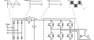
And, first of all, let’s figure out what happens in the coil itself when current flows. If the current does not change its value, then the coil has no effect on it. Does this mean that in the case of direct current the use of inductors should not be considered? Definitely not. After all, direct current can be “turned on/off”, and it is at the moments of switching that all the key processes occur. Let's look at the circuit:
In this case, the resistor acts as a load; in its place there could be, for example, a lamp. In addition to the resistor and inductance, the circuit includes a DC source and a switch with which we will close and open the circuit. What happens the moment we close the switch?
The current through the coil will begin to change, since at the previous moment in time it was equal to 0. The change in current will lead to a change in the magnetic flux inside the coil, which, in turn, will cause the occurrence of EMF (electromotive force) of self-induction, which can be expressed as follows:
\varepsilon_s = -\frac{d\Phi}{dt}
The occurrence of EMF will lead to the appearance of an induced current in the coil, which will flow in the direction opposite to the direction of the power source current. Thus, the self-induced emf will prevent current from flowing through the coil (the induced current will cancel the circuit current due to the fact that their directions are opposite). This means that at the initial moment of time (immediately after closing the switch), the current through the coil I_L will be equal to 0. At this moment in time, the self-induction emf is maximum.
And then the following will happen - since the magnitude of the EMF is directly proportional to the rate of change of current, it will gradually weaken, and the current, accordingly, on the contrary, will increase. Let's look at graphs that illustrate what we've discussed:
In the first graph we see the input voltage of the circuit - initially the circuit is open, but when the switch is closed, a constant value appears. In the second graph we see a change in the magnitude of the current through the inductor. Immediately after closing the switch, the current is absent due to the occurrence of self-induction EMF, and then begins to gradually increase.
The voltage on the coil, on the contrary, is maximum at the initial moment of time, and then decreases. The voltage graph across the load will coincide in shape (but not in magnitude) with the current graph through the coil (since in a series connection the current flowing through different elements of the circuit is the same).
A similar transient process in the circuit will be observed when the key is opened. A self-inductive emf will arise in the inductor, but the induced current in the event of an open circuit will be directed in the same direction as the current in the circuit, and not in the opposite direction, therefore the stored energy of the inductor will be used to maintain the current in the circuit:
After the switch is opened, a self-induction emf occurs, which prevents the current through the coil from decreasing, so the current does not reach zero immediately, but after some time. The voltage in the coil is identical in shape to the case of closing the switch, but opposite in sign. This is due to the fact that the change in current, and accordingly the self-inductive emf, in the first and second cases is opposite in sign (in the first case, the current increases, and in the second it decreases).
By the way, I mentioned that the magnitude of the self-induction EMF is directly proportional to the rate of change of current, and so, the coefficient of proportionality is precisely the inductance of the coil:
\varepsilon_s = -L\medspace\frac{dI}{dt}
At this point we finish with inductors in DC circuits and move on to AC circuits .
An important (!) nuance is that the voltage on the coil during the described transient processes can reach very significant values. This, in turn, can easily lead to failure of certain components that make up the circuit. For example, when controlling an inductive load using a switch on a transistor, the phenomenon of self-inductive emf with an impressive probability will lead to failure of the transistor. To protect against this, a protective diode is placed parallel to the inductive load, but today we are not talking about this, so for this aspect I will publish a separate material discussing the main nuances.
Calculation of a coil with a toroidal core
Toroidal (ring) cores, due to their ease of manufacture, are widely used in various pulse transformers, filters and chokes and provide low power consumption with minimal losses.
Toroidal core.
To calculate the inductance, it is enough to know three design parameters of such a magnetic core: D1 is the outer diameter, D2 is the inner diameter, h is the height of the core.
Calculation of the effective parameters of the core, as mentioned above, is based on two values C1 and C2, which are
where he is the effective core height,
D1 – outer diameter of the core,
D2 – internal diameter of the core.
Calculation of the effective core height he depends on the design features.
Calculation of the equivalent height of a toroidal core: rectangular section (top) and trapezoidal section (bottom).
Let's consider several cases:
a) rectangular cross-section with sharp edges
b) rectangular cross-section with rounded edges and rounding radius rs
c) trapezoidal cross-section with sharp edges
d) trapezoidal cross-section with rounded edges
Example. As an example, let's calculate the inductance of a toroidal coil having ω = 50 turns, wound uniformly on a magnetic core with the following dimensions D1 = 20 mm, D2 = 10 mm, h = 7 mm, the cross-section of the magnetic core is rectangular with rounded edges, rounding radius rs = 0, 5 mm, relative magnetic permeability of the core material μr = 1000.
Since we are only calculating inductance, there is no need to calculate coefficient C2
Calculation of a coil with a U-shaped rectangular core
Unlike toroidal cores, U-shaped cores are collapsible and consist of two parts. There are two modifications of such cores: consisting of two U-shaped parts and a U-shaped and rectangular closing plate.
Such cores are used in pulse transformers and horizontal scan transformers and, having high magnetic permeability, provide low power consumption.
U-shaped core with a rectangular cross-section: made of two U-shaped parts (left) and a U-shaped part with a closing rectangular plate (right).
To calculate the parameters of the core, consider the cross section of a closed U-shaped core
Section of a U-shaped rectangular core. This core consists of several sections l1, l2, l3, l4, l5 with different sections S1, S2, S3, S4, S5. Then the coefficients C1 and C2 will be
The unknown quantities can be found as follows
Example. It is necessary to calculate the inductance of the winding of a transformer made on a U-shaped core from Epcos type UU93/152/16, made of two U-shaped halves, core material N87 μr = 1950, number of turns ω = 150.
Core Epcos U93/76/16.
Thus, the calculated parameters of the core will be
Thus, the coefficient C1 and inductance L will be
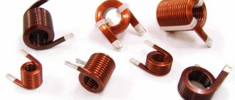
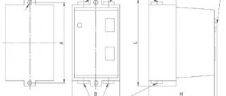
Design
The main purpose of inductors GOST 20718-75 is the accumulation of electrical energy within a magnetic field for acoustics, transformers, etc. They are used for the development and construction of various selective circuits and electrical devices. Their functionality, size and area of use depend on the design (material, number of turns), the presence of a frame. The devices are manufactured in factories, but you can make them yourself. Homemade elements are somewhat inferior in reliability to professional ones, but are several times cheaper.
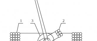
Photo - diagram
The frame of the inductor is made of dielectric material. An insulated conductor is wound around it, which can be either single-core or multi-core. Depending on the type of winding, they are:
- Spiral (on a ferrite ring);
- Screw;
- Screw-spiral or combined.
A notable feature of an inductor for electrical circuits is that it can be wound either in several layers or unified, i.e., with scraps. If a thick conductor is used, then the element can be wound without a frame, if thin, then only on a frame. These inductor frames come in different cross-sections: square, round, rectangular. The resulting winding can be inserted into a special housing of any electrical device or used openly.
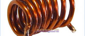
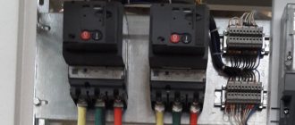
Photo - design of a homemade element
Cores are used to increase inductance. Depending on the purpose of the element, the rod material used varies:
- With ferromagnetic and air cores they are used at high current frequencies;
- Steel ones are used in low voltage environments.
At the same time, in electrical engineering, classical inductive coils without a core are actively used, which you can make with your own hands by winding them on a non-magnetic circuit. Such devices have some advantages over “core” ones. They have great impedance linearity. But, in the toroidal model, winding on a non-magnetic frame contributes to the appearance of parasitic capacitance.
Based on the principle of operation, there are the following types:
- Contour. They are mainly used in radio engineering to create oscillatory circuits on boards and work together with capacitors. The connection uses a serial connection. This is a modern version of the flat Tesla coil;
- Variometers. These are high-frequency tunable coils, the inductance of which can be controlled, if necessary, using additional devices. They represent a connection of two separate coils, one of which is movable and the other is not;
- Twin and tuning chokes. The main characteristics of these coils: low resistance to direct current and high resistance to alternating current. Chokes are made of several coils connected by windings. They are often used as a filter for various radio devices, installed to control interference in antennas, etc.;
- Communication transformers. Their design feature is that two or more coils are installed on one rod. They are used in transformers to provide a specific connection between the individual components of a device.
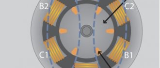
The marking of inductors is determined by the number of turns and the color of the housing.
Photo - marking