Classic connection options
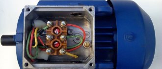
Most emails Motors for modern electric drives operate from an alternating three-phase line (each of the three phases is supplied by a separate conductor). Accordingly, the terminal box contains the terminals (input and output) of three windings. They can be connected to each other and to the network using two classic schemes: “star” and “triangle”.
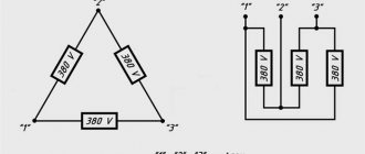
Star and Delta connection diagram
For the first, a characteristic feature is the closure of the end terminals of each coil to one point (in practice, this is one neutral). Meanwhile, the mains voltage is supplied to the input pins. This scheme is characterized by a softer ride, but unfortunately, it does not allow you to develop full power.
The second option with a triangle is characterized by a serial connection of the terminals of the windings: the end of the first is connected to the beginning of the second, etc. This starting option guarantees achievement of the rated power, but during switching on, large currents may arise that can thermally damage the winding terminals.
If you remove the terminal box cover, both connection options will look like this:
Application of magnetic contactor
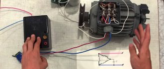
To organize a soft start, it is necessary to introduce a special switching device - a starter - into the power circuit. This is one of the connector options that can be supplemented with optional elements, for example, a thermal relay. A huge advantage of this scheme is the possibility of organizing not only the start-up of electricity. the engine, but also stopping it, reversing it, as well as protecting connections from damage by excess currents. In addition, the core or coil can have a voltage rating of 380 or 220V, which allows you to connect the motor to a power and household network.
Classic electrical circuits for connecting motors through a starter can be divided into two types:
- Irreversible. Connection of the unit and the network without the need/possibility of organizing its reverse movement. In this case, it is possible to integrate both into a power and household (220V) network,
Non-reversible connection diagram
- Reversible. An electrical circuit that combines two starters (unit) with a circuit breaker. It is also possible to change the direction of rotation of the rotor assembly for power and household (220V) networks.
Reversible connection diagram
As you can judge from the illustrations, the differences between the “network” options lie in the connection points of the contactor terminals:
- for 380 volts the contacts are closed on 2 of 3 phases,
- for 220 volts, one of the contacts is connected to the extreme phase, and the second to zero.
Thermal relay
In addition, in all four options there is an element designated as “P”. This is nothing more than a thermal relay. It is connected in series with the contactor coil and serves to protect the motor from excessive current loads.
According to the principle of operation, the thermal relay is a key, that is, when critical current values for the operation of the unit and contactor are reached, a temporary break in the power supply occurs. Some types of thermal relays or “thermal relays” are used for DC circuits or specific modes (delayed start-up, phase failure, etc.).
Constant activation of the magnetic starter leads to mechanical wear of the contacts, which a thyristor or contactless circuit does not have. The circuit is broken not mechanically (dividing the contact group), but electronically - due to diode bridges.
Using a frequency converter
Currently, everyone has quite actively begun to use frequency converters to control the rotational speed (RPM) of an electric motor.
This allows you not only to save energy (for example, when using frequency control of pumps for water supply), but also to control the supply of positive displacement pumps, turning them into dosing ones (any pumps of a positive displacement principle).
But very often when using frequency converters, they do not pay attention to some of the nuances of their use:
Operation of devices with a specific moving part
The usual version of the rotor assembly of a three-phase asynchronous electric motor is a short-circuited “squirrel cage” type, which is assembled from steel plates. When there is a need to reduce the rating of starting currents with the ability to regulate the rotation speed, then a wound rotor is used. Its characteristic feature is two groups of conclusions:
- Stator. Classic terminal block to which mains voltage is supplied (380 or 220V),
- Rotary. Additional terminal block for the terminals of the wound rotor windings, to which the contacts of the rheostat (resistance block) are connected.
The latter is necessary for a smooth start with gradual switching on/off of individual resistances in the wound rotor winding circuit.
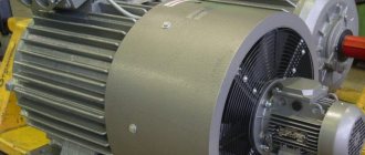
Three-phase squirrel-cage asynchronous motor
Squirrel-cage induction motor
is an asynchronous electric motor whose rotor is made with a short-circuited winding in the form of a squirrel cage [1].
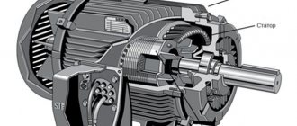
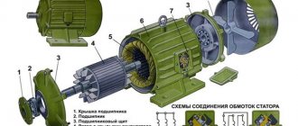
Construction of an asynchronous electric motor
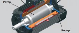
A three-phase asynchronous electric motor, like any electric motor, consists of two main parts - a stator and a rotor. The stator is the stationary part, the rotor is the rotating part. The rotor is placed inside the stator. There is a small distance between the rotor and stator, called an air gap, usually 0.5-2 mm.
Asynchronous motor stator
Asynchronous motor rotor
Stator
consists of a body and a core with a winding.
The stator core is assembled from thin sheet technical steel, usually 0.5 mm thick, coated with insulating varnish. The laminated core design contributes to a significant reduction in eddy currents arising during the process of magnetization reversal of the core by a rotating magnetic field. The stator windings are located in the slots of the core. Housing and stator core of an asynchronous electric motor
Construction of a laminated core of an asynchronous motor
Rotor
consists of a core with a short-circuited winding and a shaft. The rotor core also has a laminated design. In this case, the rotor sheets are not varnished, since the current has a low frequency and the oxide film is sufficient to limit eddy currents.
Principle of operation. Rotating magnetic field
The operating principle of a three-phase asynchronous electric motor is based on the ability of a three-phase winding to create a rotating magnetic field when connected to a three-phase current network.
A rotating magnetic field is the basic concept of electric motors and generators.
Launch
Stop
Rotating magnetic field of an asynchronous electric motor
The rotation frequency of this field, or the synchronous rotation frequency, is directly proportional to the frequency of the alternating current f1 and inversely proportional to the number of pole pairs p of the three-phase winding.
,
- where n1 is the rotation frequency of the stator magnetic field, rpm,
- f1 – alternating current frequency, Hz,
- p – number of pole pairs
Rotating magnetic field concept
To understand the rotating magnetic field phenomenon better, consider a simplified three-phase winding with three turns. Current flowing through a conductor creates a magnetic field around it. The figure below shows the field created by three-phase alternating current at a specific point in time
Launch
Stop
Magnetic field of a straight conductor with direct current
Magnetic field created by the winding
The components of alternating current will change over time, causing the magnetic field they create to change. In this case, the resulting magnetic field of the three-phase winding will take different orientations, while maintaining the same amplitude.
Magnetic field created by three-phase current at different times Current flowing in the turns of the electric motor (60° shift)
Launch
Stop
Rotating magnetic field
The effect of a rotating magnetic field on a closed loop
Now let's place a closed conductor inside a rotating magnetic field. According to the law of electromagnetic induction, a changing magnetic field will give rise to an electromotive force (EMF) in the conductor. In turn, the EMF will cause a current in the conductor. Thus, in a magnetic field there will be a closed conductor with a current, on which, according to Ampere’s law, a force will act, as a result of which the circuit will begin to rotate.
The influence of a rotating magnetic field on a closed conductor carrying current
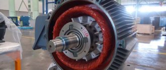
Squirrel-cage rotor of an asynchronous motor
An asynchronous electric motor also operates on this principle. Instead of a current-carrying frame, inside the asynchronous motor there is a squirrel-cage rotor whose design resembles a squirrel wheel. A squirrel-cage rotor consists of rods short-circuited at the ends with rings.
Squirrel cage rotor most widely used in induction motors (shown without shaft and core)
Three-phase alternating current, passing through the stator windings, creates a rotating magnetic field. Thus, also as described earlier, a current will be induced in the rotor bars, causing the rotor to start rotating. In the figure below you can notice the difference between the induced currents in the rods. This occurs due to the fact that the magnitude of the change in the magnetic field differs in different pairs of rods, due to their different locations relative to the field. The change in current in the rods will change with time.
Launch
Stop
Rotating magnetic field penetrating a squirrel-cage rotor
Magnetic moment acting on the rotor
You may also notice that the rotor arms are tilted relative to the axis of rotation. This is done in order to reduce the higher harmonics of the EMF and get rid of torque ripple. If the rods were directed along the axis of rotation, then a pulsating magnetic field would arise in them due to the fact that the magnetic resistance of the winding is much higher than the magnetic resistance of the stator teeth.
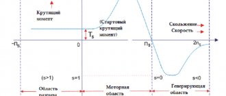
Slip of an asynchronous motor. Rotor speed
A distinctive feature of an asynchronous motor is that the rotor speed n2 is less than the synchronous speed of the stator magnetic field n1.
This is explained by the fact that the EMF in the rotor winding rods is induced only when the rotation frequencies n21 are unequal. The rotation frequency of the stator field relative to the rotor is determined by the sliding frequency ns=n1-n2. The lag of the rotor from the rotating field of the stator is characterized by a relative value s called slip:
,
- where s is the slip of an asynchronous electric motor,
- n1 – rotation frequency of the stator magnetic field, rpm,
- n2 – rotor speed, rpm,
Let us consider the case when the rotor rotation frequency coincides with the rotation frequency of the stator magnetic field. In this case, the relative magnetic field of the rotor will be constant, thus no EMF, and therefore no current, will be created in the rotor rods. This means that the force acting on the rotor will be zero. This will slow down the rotor. After which an alternating magnetic field will again act on the rotor rods, thus the induced current and force will increase. In reality, the rotor of an asynchronous electric motor will never reach the rotation speed of the stator magnetic field. The rotor will rotate at a certain speed which is slightly less than the synchronous speed.
The slip of an asynchronous motor can vary in the range from 0 to 1, i.e. 0-100%. If s~0, then this corresponds to the idle mode, when the engine rotor experiences practically no counteracting torque; if s=1 - short circuit mode, in which the motor rotor is stationary (n2 = 0). Slip depends on the mechanical load on the motor shaft and increases with its growth.
The slip corresponding to the rated load of the motor is called rated slip. For low and medium power asynchronous motors, the rated slip varies from 8% to 2%.
Energy conversion
An asynchronous motor converts electrical energy supplied to the stator windings into mechanical energy (rotation of the rotor shaft). But the input and output power are not equal to each other since energy losses occur during conversion: friction, heating, eddy currents and hysteresis losses. This energy is dissipated as heat. Therefore, an asynchronous electric motor has a fan for cooling.
Operation of DPT type P 41
An electric machine, powered by 220 V DC, has a more complex design compared to the units described above. The specifics of operation, for example, of the P 41 model, require the presence of a commutator-brush assembly, an armature coil, and auxiliary stator (inductor) poles. Motors of this model size belong to machines with an electromagnetic inductor. That is, to connect and start P 41, it is not permanent magnets that are used, but an independent or mixed excitation winding of 110 or 220V.
As you can judge, the operation of three-phase (380 V) and single-phase (220 V) AC machines or DFC type P 41 can be organized in a variety of ways, from classical to specific ones, taking into account actual operating conditions.