Connecting a three-phase asynchronous electric motor
A three-phase asynchronous electric motor and its connection to the electrical network often raises a lot of questions. Therefore, in our article we decided to consider all the nuances associated with preparing for switching on, determining the correct connection method and, of course, we will analyze possible options for switching on the engine. Therefore, we will not beat around the bush, but will immediately begin to analyze the questions posed.
Preparing an asynchronous electric motor for switching on
Types of electric motors
At the very first stage, we should decide on the type of engine that we are going to connect. This could be a three-phase asynchronous motor with a squirrel cage or wound rotor, a two- or single-phase motor, or maybe even a synchronous machine.
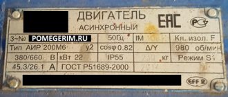
A tag on the electric motor, which contains the necessary information, can help with this. Sometimes this can be done purely visually - since we are considering the connection of three-phase electrical machines, a motor with a squirrel-cage rotor does not have a commutator, but a machine with a wound rotor has one.
Determining the beginning and end of the winding
A three-phase asynchronous electric motor has six terminals. These are three windings, each of which has a beginning and an end.
For correct connection we must determine the beginning and end of each winding. There are many options for how to do this - we will focus on the simplest of them, applicable at home.
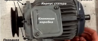
Motor stator windings
- In order to determine the beginning and end of the winding of a three-phase motor with our own hands, we must first determine the terminals of each individual winding, that is, determine each individual winding.
- This is quite easy to do. Between the end and the beginning of one winding we will definitely have a circuit. Either a two-pole voltage indicator with the appropriate function, or a regular multimeter will help us determine the circuit.
- To do this, connect one end of the multimeter to one of the terminals and touch the other five terminals in turn with the other end of the multimeter. Between the beginning and the end of one winding we will have a value close to zero, in resistance measurement mode. Between the other four pins the value will be practically infinite.
- The next step is to determine their beginning and end.
EMF for various types of connection of electric motor windings
- In order to determine the beginning and end of the winding, let's dive a little into the theory. The stator of an electric motor has three windings. If you connect the end of one winding to the end of another winding, and apply voltage to the beginning of the windings, then at the connection point the EMF will be equal to or close to zero. After all, the EMF of one winding compensates for the EMF of the second winding. In this case, no EMF will be induced in the third winding.
- Now let's look at the second option. You have connected one end of the winding to the beginning of the second winding. In this case, an EMF is induced in each of the windings, resulting in their sum. Due to electromagnetic induction, an EMF is induced in the third winding.
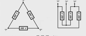
Scheme for determining the beginning and end of the motor windings
- Using this method we can find the beginning and end of each of the windings. To do this, connect a voltmeter or a light bulb to the terminals of one winding. And we connect any two terminals of other windings to each other. We connect the two remaining terminals of the windings to a 220V electrical network. Although you can use lower voltage.
- If we connect end and end of two windings, then the voltmeter on the third winding will show a value close to zero. If we connected the beginning and end of the two windings correctly, then, as the instructions say, a voltage from 10 to 60V will appear on the voltmeter (this value is very arbitrary and depends on the design of the electric motor).
- We repeat a similar experiment twice more until we accurately determine the beginning and end of each winding. To do this, be sure to sign each result obtained so as not to get confused.
Selecting a motor connection diagram
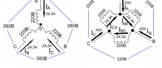
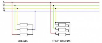
Almost any asynchronous electric motor has two connection options - star or delta. In the first case, the windings are connected to phase voltage, in the second to linear voltage.
The electric motor is three-phase asynchronous and the star-delta connection depends on the characteristics of the winding. This is usually indicated on the engine tag.
Ratings on the motor label
- First of all, let's figure out what is the difference between these two options. The most common is the star connection. It involves connecting all three ends of the windings to each other, and voltage is applied to the beginning of the windings.
- With a delta connection, the beginning of each winding is connected to the end of the previous winding. As a result, each winding turns out to be a side of an equilateral triangle - hence the name.
Difference between star and delta connections
- The difference between these two connection options is the engine power and starting conditions. With a delta connection, the motor is able to develop more power at the shaft. At the same time, the starting moment is characterized by a large voltage drop and large inrush currents.
- In domestic conditions, the choice of connection method usually depends on the available voltage class. Based on this parameter and the nominal parameters indicated on the motor plate, the method of connecting to the network is selected.
Principle of operation
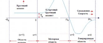
IM is based on the rotation of the magnetic field. Current flows into the winding area of a three-phase stator, and a flux of magnets appears in the phases, varying depending on the speed and frequency of constant electrical power. During stator rotation, an electromotive force is generated.
A voltage is supplied to the rotor winding, which, together with the constant magnetic flux of the stator, forms a start. It tends to direct the rotor along the magnetic rotation of the stator and, when the braking torque is exceeded, leads to slipping. It expresses the relationship between the frequencies of the stator force field of the magnets and the rotor speed.
Short circuit drawing
When there is a balance between the electromagnet and braking torques, the change in values will stop. A special feature of IM operation is the solvation of the circular motion of the stator force field and its inducing currents in the rotor. The rotation torque occurs only when the frequencies of the circular movements of the magnetic fields differ.
Machines are divided into synchronous and asynchronous. The difference between the mechanisms is in their winding. It forms a magnetic field.
The immobility of the rotor and the short circuit of the winding leads to a short circuit (short circuit).
Connecting an asynchronous motor
The three-phase asynchronous electric motor and the connection diagram depend on your needs. The most common option is a direct connection circuit; for motors connected by a delta circuit, a star connection circuit with a transition to a delta connection is possible; if necessary, a reverse connection option is possible.
In our article we will look at the most popular direct connection and direct connection circuits with the possibility of reverse.
Scheme of direct connection of an asynchronous electric motor
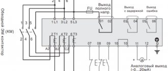
In previous chapters, we connected the motor windings, and now it’s time to connect it to the network. Motors must be connected to the network using a magnetic starter, which ensures reliable and simultaneous activation of all three phases of the electric motor.
The starter, in turn, is controlled by a push-button station - the same “Start” and “Stop” buttons in one housing.
| But before we proceed directly to the connection, let's look at what electrical equipment we need for this. First of all, this is a circuit breaker whose rated current corresponds to or is slightly higher than the rated current of the electric motor. |
| The next switching device is the starter we have already mentioned. Depending on the rated current, starters are divided into products 1, 2, etc. up to the 8th value. It is important for us that the rated current of the starter is not less than the rated current of the electric motor. |
| The starter is controlled using a push-button station. It can be of two types. With "Start" and "Stop" buttons and with "Forward", "Stop" and "Back" buttons. If we do not use reverse, then we need a push-button post with two buttons and vice versa. |
| In addition to the specified devices, we will need a cable of the appropriate cross-section. It is also desirable, but not necessary, to install an ammeter on at least one phase to monitor the motor current. |
Note! Instead of a machine, it is quite possible to use fuses. Only their rated current must correspond to the rated current of the motor. It must also take into account the starting current, which for different types of motors ranges from 6 to 10 times the rated one.
- Now let's proceed directly to the connection. It can be roughly divided into two stages. The first is connecting the power section, and the second is connecting the secondary circuits. Power circuits are circuits that provide connection between the engine and a source of electrical energy. Secondary circuits are necessary for ease of engine control.
- To connect the power circuits, we just need to connect the motor output with the first terminals of the starter, the starter terminals with the terminals of the circuit breaker, and the machine itself with a source of electrical energy.
Note! Connecting the phase outputs to the contacts of the starter and the machine does not matter. If after the first start we determine that the rotation is incorrect, we can easily change it. The engine grounding circuit is connected in addition to all switching devices.
Connection diagram of the primary and secondary circuits of the electric motor switching circuit
Now let's look at a more complex secondary circuit diagram. To do this, first of all, as in the video, we need to decide on the nominal parameters of the starter coil. It can be 220V or 380V.
- You should also deal with such an element as the starter block contacts. This element is available on almost all types of starters, and in some cases it can be purchased separately with subsequent installation on the starter body.
Location of starter elements
- These block contacts contain a set of contacts - normally closed and normally open. Let us warn you right away - don’t be alarmed, there is nothing complicated about this. A normally closed contact is a contact that is closed when the starter is in the off position. Accordingly, the normally open contact is open at this moment.
- When the starter is turned on, the normally closed contacts open and the normally open contacts close. If we are talking about a three-phase asynchronous electric motor and connecting it to the electrical network, then we need a normally open contact.
Normally closed and normally open contacts
- There are also such contacts on the push-button post. The Stop button has a normally closed contact, and the Start button has a normally open contact. First we connect the “Stop” button.
- To do this, we connect one wire to the starter contacts between the circuit breaker and the starter. We connect it to one of the contacts of the “Stop” button. There should be two wires coming off the second contact of the button at once. One goes to the contact of the “Start” button, the second to the block contacts of the starter.
Connecting the Start and Stop buttons
- From the “Start” button we lay a wire to the starter coil, and we also connect the wire from the starter block contacts there. We connect the second end of the starter coil either to the second phase wire on the power contacts of the starter, when using a 380V coil, or it is connected to the neutral wire, when using a 220V coil.
- That's it, our direct connection circuit for an asynchronous motor is ready for use. After the first turn on, we check the direction of rotation of the motor and if the rotation is incorrect, then simply swap the two power wires at the starter terminals.
Electric motor reversal circuit diagram
A common option for connecting an asynchronous electric motor is the option using reverse. This mode may be required in cases where it is necessary to change the direction of rotation of the engine during operation.
- To create such a circuit, we will need two starters, which is why the price of such a connection increases slightly. One will turn on the engine in one direction, and the second in the other. A very important point here is the inadmissibility of turning on both starters at the same time. Therefore, we need to provide blocking from such inclusions in the secondary circuit.
- But first, let's connect the power section. To do this, as in the above option, we connect the starter from the machine, and the motor from the starter.
- The only difference will be the connection of another starter. We connect it to the inputs of the first starter. In this case, an important point will be to swap the two phases, as in the photo.
Scheme of reversible connection of an electric motor with a 220V starter coil
- We simply connect the output of the second starter to the output of the first. And here we don’t change anything anymore.
- Well, now, let's move on to connecting the secondary circuit. It all starts again with the “Stop” button. We connect it to one of the incoming contacts of the starter - it doesn’t matter the first or second. From the “Stop” button we again have two wires. But now one is to pin 1 of the Forward button, and the second is to pin 1 of the Back button.
Scheme of reversible connection of an electric motor with a 220V starter coil
- The further connection is made using the “Forward” button; using the “Back” button it is identical. To contact 1 of the “Forward” button we connect the contact of the normally open contact of the starter block contacts. Pun, but you can't say it more precisely. To contact 2 of the “Forward” button we connect the wire from the second contact of the starter block contacts.
- We also connect a wire there that will go to the normally closed contact of the starter block contacts number two. And from this block contact it is connected to the starter coil number 1. The second end of the coil is connected to the phase or neutral wire, depending on the voltage class.
- The coil of the second starter is connected in the same way, only we connect it to the block contacts of the first starter. This is what ensures blocking from turning on one starter while the second one is pulled up.
Design of a reversible magnetic motor
The distribution of these modifications is becoming more widespread every year, as they help control an asynchronous motor at a distance. This device makes it possible to both turn on and off the motor .
The reversing starter housing consists of the following parts:
- Contactor.
- Thermal micro relay.
- Casing.
- Management tools.
After the “Start” command has been received, the circuit is closed. Next, the current begins to be transmitted to the coil. At the same time, a mechanical blocking device operates, which prevents unnecessary contacts from starting. It should be noted here that the mechanical lock also closes the contacts of the key, this makes it possible not to keep it pressed constantly, but to calmly release it. Another important part is that the second key of this device, together with the start of the entire device, will open the electrical circuit. Thanks to this, even pressure produces virtually no result, creating additional safety.
Features of the model's functioning
Pressing the Forward key activates the coil and makes contacts. At the same time, the operation of the start key is performed by constantly open contacts of the KM 1.3 device, due to which, when the key is directly released, the power to the coil acts bypass.
After introducing the first starter, it is the KM 1.2 contacts that open, which turns off the K2 coil. As a result, when you directly press the “Back” key, nothing happens. In order to turn the motor in the opposite direction, you need to press “Stop” and turn off the power to K1. All blocking contacts can return to the opposite state, after which it is possible to drive the motor in the opposite direction. In the same way, K2 is introduced and the block with contacts is turned off . Coil 2 of starter K1 is turned on. K2 contains power contacts KM2, and K1 - KM1. A five-core wire should be connected to the buttons for connection from the starter.
Connection rules
In any installation that requires starting an electric motor in the forward and opposite directions, there is certainly an electromagnetic device with a reversible circuit. Connecting such an element is not considered as difficult a task as it might seem at first glance. In addition, the need for such tasks arises quite often. For example, in drilling machines, cutting structures or elevators, if this does not apply to home use.
Direct start of the electric motor
Now the most common and accessible way to start an asynchronous electric motor is a direct connection to a three-phase network. It consists of directly connecting the power unit to the mains power source. This simple technology is often used to organize a stable voltage to start a three-phase motor rigidly coupled to an electric drive, for example, in pumping equipment.
An electronic magnetic starter or contactor is used here as an auxiliary device. To protect the motor from current overload during operation, a special relay is used. The design of modern power units of medium and low power usually provides for a direct connection of the stator windings to the electrical network so that during the action of starting currents no excessive electrodynamic forces arise, and the engine temperature remains within the permissible range.
Direct starting of an asynchronous three-phase motor is most appropriate in the following cases:
- the electrical installation has low power;
- there are no strict restrictions on current strength;
- the connected equipment or technical process does not require smooth or stepwise acceleration;
- the mechanisms are started without load.
As a rule, in low-power electric motors the starting torque and current occur within 150-300% and 300-700% of the nominal value, respectively. Directly connecting the motor is not recommended when the drive is operating as part of inertial equipment or when the power supply is limited.
Calculation of the number of repetitions
Let's take m1 - the process of repeating the constant field of magnets and the rotor. The AC phase system forms a rotating magnetic field.
Calculation data is calculated using the formula:
f1 – frequency of electricity$
p – the number of pole pairs of each stator winding.
m2 – the process of repeating the rotation of the rotor. Having a different number of simultaneous repetitions, a given frequency rate will be asynchronous. The frequency calculation is determined by the relationship between the data:
An asynchronous electric motor operates only at asynchronous frequency.
(m2 Rheostat start
Often rheostats provide the necessary effect to turn on the engine of powerless starting torques. Diagram of the rheostat method:
The main characteristic of the method is the connection of the engine to rheostats when starting. The rheostats break (in the drawing K1), and a partial electric current flows through them. This makes it possible to reduce inrush currents. The starting torque is also reduced. The advantage of the rheostatic method is to reduce the load on the mechanical part and the lack of voltage.