Good day to all. Today we continue the topic about rectifiers and we’ll talk about smoothing filters for rectifiers
. Smoothing filters are connected between the rectifier and the load to reduce the variable components (ripple) of the rectified voltage. These filters are made of inductive elements - chokes and capacitive elements - capacitors. The simplest anti-aliasing filter can consist of only one element, for example an inductor or a capacitor. In small-sized equipment with relatively low power, inductive filter elements can be replaced by active ones (resistors).
Smoothing filters are primarily characterized by a smoothing coefficient q, which is the ratio of the ripple coefficients at the input S0 and the output S0H of the filter:
To assemble a radio-electronic device, you can pre-make a DIY KIT kit using the link.
Inductive Antialiasing Filter
It is used in low-power rectifiers, but can be part of complex multi-section filters. The inductor parameters should be selected so that the active winding resistance rdr is much less than the load resistance (rdr << Rn), and the inductive resistance Xdr = 2πfпLф at the pulsation frequency fp is much greater than Rn (Xdr >> Rn). In this case, almost the entire DC component of the voltage will be applied to the load, and the AC component will be applied to the inductor.
Using a given smoothing coefficient q, you can calculate the required inductance of the smoothing filter
The inductive filter is simple, cheap, and has low power losses; The filter smoothing coefficient increases with increasing inductance of the inductor, the number of phases of the supply voltage and with decreasing load resistance. Therefore, inductive filters are usually used in conjunction with multiphase powerful rectifiers. When the load is disconnected or its resistance changes abruptly, overvoltages may occur; in this case, it is necessary to include protective devices, such as arresters, in parallel with the inductor winding. In low-power single-phase rectifiers, the inductive filter can be a part of a more complex filter.
Schematic diagram of the filter
Let us first consider the filter circuit shown in Fig. 3. For greater efficiency, it is made of two stages and differs from the classic one only in that the inductor coils L1 - L2 and L3 - L4 are made on a magnetic core and, thanks to the magnetic coupling between the windings, provide more effective suppression of low-frequency interference induced simultaneously on both wires of the line (common mode) .
To do this, you must observe the phasing of the connection of the terminals, as shown in the diagram, and also ensure that the winding of the coils is symmetrical - in this case, there will be no bias in the magnetic circuit of the core. Coils L1 - L2 and capacitors C1 - C2 provide suppression of the highest frequency interference, and L3 - L4 and the remaining capacitors - suppress frequencies below 200 kHz.
Rice. 3. Scheme of a two-stage 220V surge protector for self-production.
Windings L1 and L2 contain 12 turns each and are wound with nichrome wire (00.8...0.9 mm) on a ring ferrite core M2000NM of standard size KZ 1x19x7.5 with a small pitch (to reduce the interturn capacitance).
The windings are located separately on opposite parts of the core, with a gap between the winding terminals (2...4 mm). Thanks to the use of nichrome (you need two pieces of approximately 450 mm in length), these coils will simultaneously act as current-limiting resistors (with a resistance of about 0.8 Ohms), which will be required in the future if we introduce impulse noise protection elements into the circuit. Their inductance is approximately 0.16 mH.
Before winding the coils, the sharp edges of the magnetic circuit must be rounded with sandpaper or a file, after which the core is wrapped with fluoroplastic tape in two layers.
The windings of coils L3 and L4 have an inductance of 0.7 mH - it is advisable to verify this with the device and achieve their symmetry, i.e., the same inductance values. Any iron from a network transformer will be suitable as a core, but it will be possible to obtain the minimum design dimensions only by using a ring magnetic core made of ferrite grade M1000...M4000NM (K40x25x7.5 - 2 pieces) or, even better, al-sifer alloy MP 140 of standard size KP36x25x7, 5 (2 parts).
So, for example, for an MP140 brand core, in order to obtain the specified inductance, you will need to wind each winding 70 turns with PEV wire with a diameter of 0.85 mm (winding turn to turn).
But since the entire winding will not fit in one layer, the rest of it is wound after insulating the first layer (on opposite sides of the coils leave a gap of 2...3 mm between the windings). The appearance of the winding and the location of the windings for T2 are shown in Fig. 4. It is better to use narrow (5 mm) fluoroplastic tape as an insulating material.
The coils themselves are fixed on the board with a long screw, as shown in Fig. 4, 6.
When installing coils on the board, you need to place an asbestos or mica gasket under T1 - in this case, if overloaded, heating the winding will not damage the board. And since nichrome is difficult to solder, the terminals of the coils L1 and L2 are attached to the printed circuit board with M2.5x6 screws.
In order to ensure effective operation of the filter at high frequencies, during the manufacture of all capacitors in the first stage, it is necessary to use high-frequency capacitors from series that allow operation on alternating current at a voltage of at least 500 V, for example K15-5-1.6 kV (values can be used and larger than indicated in the diagram, if the dimensions of the parts allow them to be placed on the printed circuit board below).
Rice. 4. Design and type of winding of coils on the MP 140 magnetic circuit.
Since such capacitors are not produced at large values, it is necessary to increase the inductance of the coils and use additional low-frequency capacitors C5-C7 - they can effectively suppress low-frequency interference of domestic and industrial origin penetrating from the network. As domestic capacitors C5-C7, you can use K73-16V, K73-15, K73-11, K42U-2 at 630 V or similar.
It would seem that for better filtering it is necessary to significantly increase the capacitance of the input capacitors, but at the same time the reactive component of the power in the circuit also increases, which is bad. For this reason, usually an input capacitance of more than 1 μF is not used, but such capacitors are also structurally inconvenient due to their large dimensions.
If anyone is interested in a complete engineering calculation of a network filter, it can be found in the book [L 19]. Here we will provide only the minimum necessary information that may be useful now.
The diameter of the wire for winding coils L3-L4 depends on the maximum current (sum of currents) of all consumers that you want to receive at the filter output as follows:
Where:
- d—wire diameter, mm;
- I is the maximum effective current in the circuit, A;
- j is the permissible maximum current density, A/mm2 (in this case, it can be taken anywhere from the range 6... 10 A/mm2).
At a maximum current density of 8 A/mm2, the wire diameter for a current of 10 A will be 1.26 mm (Pload = 2.2 kW - such power is unlikely to be needed); for 8 A - 1.13 mm (Pload = 1.76 kW); for 4.54 A - 0.85 mm (Pload = 1 kW).
Since it is more convenient to have two 1 kW filters than one 2.2 kW filter, we will focus on a lower power (1 kW) and choose a wire with a diameter of 0.85 mm for winding.
The design of the filter is also of great importance. It is necessary to exclude the penetration of interference from input to output through parasitic installation capacitances and electromagnetic coupling, for which it is necessary to ensure shielding of the cascades highlighted in the dotted line in the diagram.
To indicate the presence of voltage at the contacts of the output sockets, use the HL1 LED (any of the KIPD series is suitable). As a connecting cable, you can use a flexible stranded wire having 3 cores with a cross-section of each of at least 0.75 mm2.
Capacitive anti-aliasing filter
Capacitive anti-aliasing filter
consists of a capacitor Sf connected in parallel with the load resistance Rн. The principle of operation is the accumulation of electrical energy by the filter capacitor and the subsequent release of this energy to the load. The charge and discharge of the filter capacitor occurs with the pulsation frequency fп of the rectified voltage.
To calculate the capacitance of the anti-aliasing filter capacitor
you can use the following formula
, Where
the resulting capacitance value is expressed in microfarads, SOH is the ripple coefficient in percent, %; RH – load resistance in ohms, Ohm; fc – network frequency in hertz, Hz; m is the number of half-cycles used during rectification per period of the network voltage, m = 1 – for half-wave, m = 2 – for full-wave.
It is best to use a capacitive filter in conjunction with single-phase and low-power rectification circuits.
DIY surge protector
The simplest filter circuit consists of a switch and a varistor, this is what it looks like:
V1 is a varistor, its marking “471” means that its operating voltage is 470V, and the larger its diameter, the more energy it can absorb without exploding. This means that the larger the varistor you install, the better, as long as it fits in size. Here is an example of a surge protector assembled according to this scheme, but in a factory version. From the above it follows that this is a cheap device that does not filter what it should, but only dampens impulses.
In order for your surge protector to actually be a noise filter, you need to add a filter element - a choke.
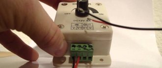
Schemes are, of course, good, but how to make a surge filter from improvised means? Simple enough! Almost always, when someone who likes to tinker with something, you can find an old unnecessary or non-working power supply, it has such a filter at the input. All that remains is to unsolder it. In the photo he stands in the corner of the board closest to us.
This is a choke with two windings, a phase passes through one of them, and zero passes through the other, so the inductance is part of the network filter and reduces the level of interference.
By the way, the power supply can work without it, many Chinese make their products this way, this is often found in cheap power supplies for computers and not only.
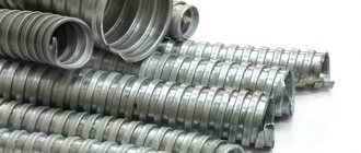
If you do not find such an element in your supplies, you can look for a ferrite ring with a magnetic permeability of 400-2000 nm and wrap it with PEV-2 wire (can be wound from a 50 Hz network transformer). Wrap it around the ring as shown in the picture.
Do not allow inter-turn short circuits and leave gaps as shown here, otherwise you will get fireworks from the phase jumping to zero. Cut the loop at the end; ideally, wind it with two wires at once. Before winding, apply an insulating layer, for example, made of varnished fabric, to the ring.
A good diagram that is easy to do with your own hands looks like this:
And here is a version of its implementation “in hardware”. A pair of filters from the power supply is taken as a basis.
It is better to use ceramic or film capacitors. They can also be taken out of the power supply; they are often found there in a rectangular case with sharp corners (parallelepiped).
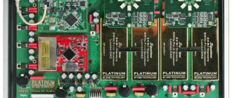
If you have an unnecessary power supply, you can simply cut off part of the board with the filter and use it. Here is an example in the photo indicating what needs to be sawed off to get a surge protector in a couple of minutes.
And here is another version of the scheme to repeat. This is what is used in many ATX power supplies:
A surge protector is a useful and simple device that is not difficult to make yourself at home. And if we take into account all the abundance of technology that has passed through modern ordinary people and the fact that many have several unnecessary and inoperative devices, then spare parts are literally lying around under our feet.
Anti-aliasing RC filters
In low-power rectification circuits, the filter choke can be replaced by an RF resistor. These types of filters are called RC filters
The calculation of the anti-aliasing RC filter must take into account the following conditions:
Filter smoothing factor
The resistance of the resistor RF is usually set within the range RF = (0.15...0.5)RH; The efficiency of a resistive-capacitive filter is relatively small and usually amounts to 0.6...0.8, and at ηф = 0.8 RF = 0.25RH. Capacitance Cf (in microfarads), provides the required smoothing coefficient q at a network frequency fC = 50 Hz, found from the expression
Advantages of resistive-capacitive filters: small dimensions, weight and cost; disadvantage - low efficiency.
Device
If we talk about the design of such a thing as a surge protector, then it should be said that it can belong to one of 2 categories:
- stationary-multichannel;
- built-in
In general, the circuit of a conventional surge protector designed for a voltage of 220 V will be standard and, depending on the type of device, may differ only slightly.
If we talk about built-in models, their peculiarity is that the contact boards of such filters will be part of the internal structure of electronic equipment.
Other equipment also has such boards, which falls into the category of complex ones. Such boards usually consist of the following components:
- additional type capacitors;
- induction coils;
- toroidal type throttle;
- varistor;
- thermal type fuse;
- VHF capacitor.
A varistor is a resistor that has variable resistance. If the standard voltage threshold of 280 volts is exceeded, then its resistance decreases. Moreover, it can decrease by more than ten times. A varistor is essentially a surge protector. And stationary models usually differ in that they have several outlets. Thanks to this, it becomes possible to connect several models of electrical equipment to the electrical network through a surge protector.
In addition, all surge protectors are equipped with LC filters. Such solutions are used for audio equipment. That is, such a filter is noise suppressing, which will be extremely important for audio and working with it. Also, surge protectors are sometimes equipped with thermal fuses, which help prevent voltage surges. Sometimes some models use disposable fuses.
Multi-link anti-aliasing filters
If using an inductive-capacitive filter it is necessary to ensure a ripple smoothing coefficient of more than 40...50, then instead of a single-section filter it is more advisable to use a two-section smoothing filter
.
Filters with three or more sections
in practice they are rarely used. In the general case, the smoothing coefficient of a multi-link filter is equal to the product of the smoothing coefficients of individual links: q = q'q''q''' ...
Smoothing inductive-capacitive filters are quite simple and effective in rectifier devices of medium and high power. However, the mass and dimensions of such filters are very significant, the smoothing coefficient decreases with increasing load current, and the filters are ineffective when slow changes in the mains voltage occur. Inductive filter elements are sources of magnetic stray fields, and together with parasitic capacitive elements they create oscillatory circuits that contribute to the appearance of transient processes.
Transistor anti-aliasing filter
Transistor filters
Compared to inductive-capacitive smoothing filters, they have smaller dimensions, weight and a higher ripple smoothing coefficient.
Filters can be made according to circuits with a power transistor connected in series or in parallel with respect to the load resistance, as well as with a load RH connected to the collector or emitter circuit of the transistor. The disadvantage of filters with a load in the collector circuit is the large change in output voltage when the load resistance changes. Therefore, filters are more often used in which the load resistance is included in the emitter circuit of the power transistor.
Filter with series transistor
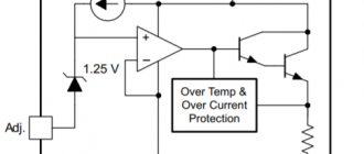
Transistor smoothing filter with serial connection of a transistor and a load in the emitter circuit
equivalent to a U-shaped LC filter. Its operating principle is based on the fact that the collector and emitter currents of the transistor in amplification mode are practically independent of the collector-emitter voltage. If you select the operating point of the transistor on the horizontal section of the output current-voltage characteristic, then its resistance for alternating current will be significantly greater than for direct current.
Transistor filter
In the circuit, the base current of the transistor VT is set by the resistor Rb. Capacitor Sat of a sufficiently large capacity eliminates the ripple voltage at the emitter-base junction. Therefore, the alternating component of the ripple voltage is applied to the base-collector junction and is allocated to the transistor VT. There is practically no alternating component in the collector and emitter current, so the ripple in the RH load is also very small.
The smoothing coefficient of the transistor filter is greater, the greater the current transfer coefficient of the transistor VT and the greater the value of the ratio
that is, the lower the ripple voltage at the emitter-base junction of the power transistor.
Composite transistor
To more successfully fulfill these relationships, the capacitor Sb can be replaced with a single- or two-section RC smoothing filter, and to increase the current transfer coefficient, the transistor VT can be made as a composite
Transistor filter with zener diode
a zener diode connected to the base circuit of the transistor works even more efficiently.
The lower the DC voltage drop across the power transistor, the greater the efficiency of the transistor filter. However, the amplitude of the alternating voltage component on the transistor should not exceed the value of the direct voltage across it, otherwise the filter will lose its functionality.
Parallel transistor filter
Filter with a ballast resistor and parallel connection of a transistor Filter with a ballast resistor and series connection of a transistor
Transistor filters with a ballast resistor Rbl and parallel connection of a transistor
relative to the load, unlike
circuits with series connection
, it is used at a relatively small rectified voltage (tens of volts). The operating mode of the transistor VT - the minimum current value IK.min - is set by the appropriate choice of resistances R1 and R2. The alternating voltage component in this circuit is applied to the emitter-base junction of the transistor VT, amplified and released at the ballast resistor Rbl. This component turns out to be in antiphase with the alternating voltage component, released on Rbl when the load current flows directly. By choosing Rbl and IK.min, you can achieve their full compensation. The amplitude of the alternating component of the transistor current VT must be less than the flowing direct current IK.min, otherwise the circuit will be inoperable. The current IK.min should not be very small, since otherwise an increase in resistance Rbl will be required, which will lead to a decrease in the filter efficiency. Too much current is also impractical, since the power loss on the transistor increases and the efficiency decreases.
The smoothing coefficient of a parallel transistor filter will be greater, the greater the resistance Rbl, the capacitance of capacitors C1 and C2, and the steepness of the current-voltage characteristic of the transistor. The disadvantage of a transistor filter with parallel connection of a transistor is a significant change in the average value of the collector current of the transistor when the average value of the rectified voltage supplied to the filter input changes. This leads to a decrease in filter efficiency.
It should be remembered that transistor filters do not provide stabilization of the constant component of the rectified voltage, and when the load current changes, the ambient temperature and the influence of other destabilizing factors, they introduce additional instability of the rectified voltage.
Theory is good, but you need to practice it all practically. YOU CAN TRY HERE
Surge filters often use tricky capacitors with inscriptions that are incomprehensible to many - X1, Y2, etc. These are noise suppression capacitors. This article will help you understand why they are needed and how they differ from “just capacitors.”
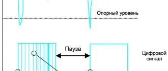
There has always been enough interference in the network - at first it appeared from brushed motors, and now it is produced on an industrial scale by switching power supplies. The fact that interference is bad is not worth repeating once again. The mains voltage in extreme cases looks something like this:
It can be seen that this is very different from the sinusoid that should be there. In order to get rid of interference, you need to create an unobstructed path along which the interference current can return to the source. Typically, this path, according to Murphy's law, lies through the most sensitive equipment. Our task is to make sure that the interference does not “want” to get into the “tender places” of our circuits, but to allow the interference current to flow where it “wanted” to flow (to the neutral, for example). On the other hand, you can avoid bringing the network to a deplorable state without releasing interference outside the device.
In order to reduce interference, filters are used. The type of filter and even its location depends on the specific case. For example, if interference is created by one source (an engine, for example), then it is best to place the filter closer to this source - short-circuit the interference current (as in the figure above).
If interference is created by a distributed circuit in a metal case (computer power supply), then it is better to place the filter as close as possible to the power cord - short-circuit the interference current inside the case and connect the case to the “cleanest” place in the circuit so that it does not radiate itself.
The figure shows a typical filter circuit for a computer power supply. Red shows the path of radiated interference, and green shows the path of interference transmitted through the wires.
The interference has two components – in-phase and anti-phase.
The antiphase component of the interference is the interference voltage between phase and neutral. To suppress it, type X capacitors are used. The name X itself comes from the English “across-the-line”, the letter X looks like a cross (“cross”). In the figure above, this is the capacitor - C1.
These capacitors are subject to the following requirements: they must withstand the maximum permissible surges in the network, not catch fire when they fail, and not sustain combustion.
There are two main subclasses of X-capacitors currently in use – X1 and X2.
- X1 – used in industrial devices connected to a three-phase network. These capacitors are guaranteed to withstand a voltage surge of 4kV.
- X2 is the most common class of capacitors. Used in household appliances with a rated network voltage of up to 250V, withstand a surge of up to 2.5kV.
The capacitance of X capacitors varies from 0.1uF to 1uF. What capacitance you need to choose for this particular device can only be determined with an oscilloscope.
The common mode component of the interference is the interference voltage between both mains wires and the device body. Understanding what it is and why it is needed is a little more difficult.
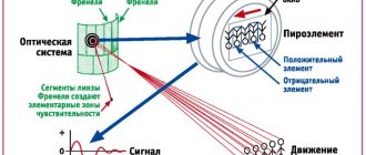
Consider a typical switching power supply. There is always a stray capacitance between the primary and secondary windings of transformer T1 (drawn in green). Let's imagine that there is no capacitor C7 yet. High-frequency ripples freely penetrate from the drain of the transistor (the noisiest place in the circuit!) to the secondary winding through the green capacitance. Thus, throughout the entire output part of the power supply there is ripple (at the frequency of the power supply) relative to ground and both network wires. The voltage of these ripples can reach thousands of volts. Our mega-sensitive device will emit these pulsations into the air, and emitting interference is the same as catching interference only with the opposite sign. The device will be bad.
Now let's add capacitor C7. The interference current that leaked through the green capacitor can now return to where it came from along a shorter and less complicated path than in the previous case, and it no longer wants to flow into our mega-sensitive device!
Notice that capacitor C7 now connects the mains to the power supply output! But this is dangerous! A person who touches simultaneously the output of such a power supply (to the body of the device) and the ground (to a heating battery, for example), will receive a noticeable, but not terrible blow. What happens if capacitor C7 breaks? That's right, the output of the power supply will become an “electric chair”. That is why Y-type capacitors were made - they are designed to work in places where their failure threatens people's lives .
Y-type capacitors are divided into 2 main classes
- Y1 – Operate at rated mains voltage up to 250V and withstand pulse voltage up to 8kV
- Y2 – The most popular type, can be used at mains voltages up to 250V and can withstand pulses of 5kV
Now some facts.
- Y type capacitors can be used instead of X type capacitors, but X type capacitors cannot be used instead of Y type capacitors.
- Y type capacitors usually have a much lower capacitance than X type capacitors.
- If for X type capacitors the more capacitance the better, then the capacitance of Y type capacitors should be chosen as small as possible. The typical value of 2.2nF already beats quite well if you grab the power supply output and the battery.
- Despite all safety measures, manufacturers recommend unplugging the plug from the socket when you leave the house for a long time.
I also recommend reading the document
CAPACITORS FOR RFI SUPPRESSION OF THE AC LINE: BASIC FACTS
rfi_fact.pdf