The three-phase electric current system was developed at the end of the 19th century by the Russian scientist M.O. Dolivo-Dobrovolsky. Three phases, the voltage in which is shifted relative to each other by 120 degrees, among other advantages, make it easy to create a rotating magnetic field. This field carries with it the rotors of the most common and simplest three-phase asynchronous electric motors.
The three stator windings of such electric motors are in most cases connected to each other in a star or delta configuration. In foreign literature, the terms “star” and “delta” are used, abbreviated as S and D. The mnemonic designation D and Y is more common, which can sometimes lead to confusion - the letter D can be marked with both “star” and “triangle”.
Star and triangle connection principle. Features and operation
To increase the transmission power without increasing the network voltage, to reduce voltage ripple in power supplies, to reduce the number of wires when connecting the load to the power supply, various circuits for connecting the windings of power sources and consumers (star and delta) are used.
Scheme
The windings of generators and receivers when working with 3-phase networks can be connected using two circuits: star and triangle. Such circuits have several differences among themselves; they also differ in current load. Therefore, before connecting electrical machines, it is necessary to find out the difference in these two circuits - star and triangle.
Star diagram
Connecting different windings according to a star circuit involves connecting them at one point, which is called zero (neutral), and is designated on the diagrams “O”, or x, y, z. The neutral point may have a connection to the power supply neutral point, but not all cases have such a connection. If there is such a connection, then such a system is considered 4-wire, and if there is no such connection, then it is considered 3-wire.
Triangle diagram
With this scheme, the ends of the windings are not combined into one point, but are connected to another winding. That is, the result is a circuit similar in appearance to a triangle, and the windings in it are connected in series with each other. It should be noted that the difference from the star circuit is that in the delta circuit the system is only 3-wire, since there is no common point.
In a triangle circuit, when the load is off and the EMF is symmetrical, it is 0.
Phase and linear quantities
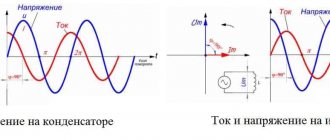
In 3-phase power networks there are two types of current and voltage - phase and linear. Phase voltage is its value between the end and beginning of the receiver phase. Phase current flows in one phase of the receiver.
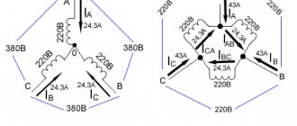
When using a star circuit, the phase voltages are Ua, Ub, Uc , and the phase currents are I a, I b, I c . When using a delta circuit for load or generator windings, phase voltages are Uaв, Ubс, Uca , phase currents are I ac, I bс, I са .
Linear voltage values are measured between the beginnings of phases or between linear conductors. Line current flows in the conductors between the power source and the load.
In the case of a star circuit, linear currents are equal to phase currents, and linear voltages are equal to U ab, Ubc, U ca. In a triangle circuit, everything turns out the other way around - phase and linear voltages are equal, and linear currents are equal to I a, I b, I c .
Great importance is given to the direction of the EMF of voltages and currents in the analysis and calculation of 3-phase circuits, since its direction affects the relationship between the vectors on the diagram.
Features of the circuits
There is a significant difference between these schemes. Let's figure out why different circuits are used in different electrical installations, and what their features are.
When starting an electric motor, the starting current has an increased value, which is several times greater than its rated value. If this is a low-power mechanism, then the protection may not work. When a powerful electric motor is turned on, the protection will definitely work, turning off the power, which will cause a voltage drop for some time and blown fuses, or turn off the electrical circuit breakers. The electric motor will operate at a low speed, which is less than the rated speed.
It can be seen that there are many problems arising due to the high inrush current. It is necessary to somehow reduce its value.
To do this, you can use some methods:
- Connect a rheostat, inductor, or transformer to start the electric motor.
- Change the type of connection of the electric motor rotor windings.
In industry, the second method is mainly used, since it is the simplest and gives high efficiency. The principle of switching the windings of an electric motor to circuits such as star and triangle works here. That is, when the motor is started, its windings have a “star” connection, after a set of operating speeds, the connection diagram changes to “triangle”. They have learned to automate this switching process in industrial settings.
In electric motors, it is advisable to use two circuits at once - star and triangle. It is necessary to connect the neutral of the power source to the zero point, since when using such circuits there is an increased likelihood of phase amplitude distortion. The source neutral compensates for this asymmetry, which arises due to different inductive resistances of the stator windings.
Advantages of the schemes
Star connection has important advantages:
- Smooth start of the electric motor.
- Allows the electric motor to operate with the declared rated power corresponding to the passport.
- The electric motor will have a normal operating mode in various situations: with high short-term overloads, with long-term minor overloads.
- During operation, the motor housing will not overheat.
The main advantage of the triangle circuit is to obtain the highest possible operating power from the electric motor. It is advisable to maintain operating modes according to the engine passport. When studying electric motors with a triangle circuit, it turned out that its power increases 3 times compared to a star circuit.
When considering generators, the star and delta circuits are similar in parameters to the operation of electric motors. The output voltage of the generator will be higher in a delta circuit than in a star circuit. However, as the voltage increases, the current decreases, since according to Ohm's law these parameters are inversely proportional to each other.
Therefore, we can conclude that with different connections of the ends of the generator windings, two different voltage ratings can be obtained. In modern powerful electric motors, when starting the circuit, star and delta switch automatically, as this makes it possible to reduce the current load that occurs when starting the motor.
How to reduce starting currents of an electric motor?
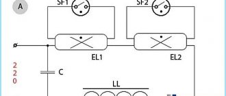
The phenomenon of a significant increase in inrush currents when starting high-power devices connected according to the Δ circuit leads in networks with overload to a short-term voltage drop below the permissible value. All this is explained by the special design of the asynchronous electric motor, in which the rotor with a large mass has high inertia. Therefore, at the initial stage of operation, the motor is overloaded, this is especially true for the rotors of centrifugal pumps, turbine compressors, fans, and machine tools.
To reduce the influence of all these electrical processes, they use a “star” and “delta” connection to the electric motor. When the engine picks up speed, the knives of a special switch (a starter with several three-phase contactors) transfers the stator windings from the Y circuit to the Δ circuit.
To implement mode changes, in addition to the starter, you need a special time relay, thanks to which there is a time delay of 50-100 ms when switching and protection against three-phase short circuits.
The very procedure of using the combined Y/Δ circuit effectively helps to reduce the inrush currents of powerful three-phase units. This happens as follows:
When a voltage of 660 V is applied according to the “triangle” circuit, each stator winding receives 380 V (√3 times less), and, therefore, according to Ohm’s law, the current strength decreases by 3 times. Therefore, when starting, the power in turn decreases by 3 times.
But such switching is possible only for motors with a rated voltage of 660/380 V when they are connected to a network with the same voltage values.
It is dangerous to connect an electric motor with a rated voltage of 380/220 V to a 660/380 V network; its windings can quickly burn out.
And also remember that the switching described above cannot be used for electric motors that have a load without inertia on the shaft, for example, the weight of a winch or the resistance of a piston compressor.
For such equipment, special three-phase electric motors with a wound rotor are installed, where rheostats reduce the value of currents during startup.
To change the direction of rotation of the electric motor, it is necessary to swap any two phases of the network for any type of connection.
For these purposes, when operating an asynchronous electric motor, special manual control electrical devices are used, which include reversing switches and batch switches or more modernized remote control devices - reversing electromagnetic starters (switches).
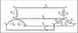
Connecting energy receivers in a triangle
When connecting energy receivers with a triangle (Fig. 6-11), each phase of the receiver is connected to the linear wires, i.e., it is switched on to the line voltage, which will also be the phase voltage of the receiver:
Thus, changing the phase resistance does not affect the phase voltages.
We will take the directions of linear currents from the generator to the receiver as positive (Fig. 6-11). Directions of phase currents from A'
to
B',
from
B'
to
C
' and from
C'
to
A'
will also be taken as positive.
According to Kirchhoff's first rule for instantaneous current values for node A'
you can write:
Similarly for node B':
Rice. 6-11
. Connecting receivers in a triangle
Consequently, the instantaneous value of any line current is equal to the algebraic difference of the instantaneous values of the currents of those phases that are connected to a given wire.
Rice. 6-12.
Vector diagram when connecting receivers in a triangle.
The vector of any line current is found as the difference between the vectors of the corresponding phase currents:
In Fig. 6-12 shows a vector diagram for a three-phase circuit when connecting energy receivers with a triangle. In this diagram, all vectors are drawn from the same origin. In Fig. 6-13 shows a second diagram for the same circuit, on which the voltage vectors form a triangle, and the vector of each phase current is drawn from the same origin with the vector of the corresponding phase voltage.
Rice. 6-13.
Vector diagram when connecting receivers in a triangle.
If, with a symmetrical system of linear voltages, the phase load is uniform, i.e.
then the effective values of the phase currents are equal to each other and they are shifted in phase by equal angles from the corresponding voltages (Fig. 6-14) and, therefore, by angles of 120° relative to each other. Therefore, the phase currents represent a symmetrical system. Linear currents will also represent a symmetrical system (Fig. 6-14).
By restoring the perpendicular from the middle of the linear current vector, for example IA,
we obtain a right triangle
OHM,
from which it follows that
Thus, when connecting receivers in a triangle with a uniform phase load, the linear currents are √3 times greater than the phase currents.
In addition, from the same vector diagram it follows that linear currents lag behind the corresponding phase currents at angles of 30°.
Rice. 6-14.
Vector diagram for a circuit connected by a triangle with a uniform phase load.
When connecting receivers in a triangle with a uniform phase load, the calculation of a three-phase circuit is reduced to the calculation of one phase.
in phase voltage are determined from the expressions
Active power of one phase
Three phase reactive power
Three-phase apparent power
If the phase load is uneven, the power of a three-phase circuit is determined as the sum of the powers of the individual phases.
If the energy receivers are connected by a star and the positive direction of the linear currents is taken to be the direction from the generator to the consumer, then according to Kirchhoff’s first rule for the neutral point we can write:
If the energy receivers are connected by a triangle, then the sum of the line currents
Consequently, for any method of connecting receivers, the algebraic sum of the instantaneous values of the linear currents of a three-phase three-wire circuit is equal to zero.
Therefore, for example, the magnetizing force of the three cores of a three-phase cable is zero and, therefore, there is no magnetization of the steel armor of the cable used to protect against mechanical damage.
Designation of linear voltages
In Figure 2, e, line voltages are designated not only as the difference between the corresponding phase voltages, but also by one letter with two indices, in our example Uab (Ubc and Uca). The order of the indices is not arbitrary: it shows in which direction the subtraction was performed.
So, we subtracted a value equal to it in magnitude from one phase voltage, but we did not get zero, but a value 1.73 times greater. This result is not unexpected, since it was not algebraic, but geometric subtraction that was performed.
Let us take this opportunity to emphasize another important circumstance that we will encounter more than once in the future. It consists in the fact that when geometrically subtracting one quantity from another equal in absolute value1, in contrast to algebraic subtraction, one can obtain not only zero, but also any quantity ranging from zero to double the value. What has been said here is illustrated in Figure 3 with several examples. On the left, vectors that are in phase are subtracted (0° shift), and, naturally, zero is obtained. To the right, vectors shifted by 45° are subtracted: the difference is equal to 0.707 of the length of any of them, and so on. And finally, in Figure 3 on the right, the difference turned out to be twice as large as the one being reduced.
Figure 3. The difference between the vectors depends on the size of the angle between them.
INCLUSION OF ENERGY RECEIVERS INTO THE THREE-PHASE CURRENT NETWORK
Electric lamps are manufactured for rated voltages of 127 and 220 V, and three-phase electric motors for rated phase voltages of 127, 220 and 380 V
and higher.
The method of connecting the receiver to a three-phase current network depends on the line voltage of the network and on the rated voltage of the receiver.
Lamps with a nominal voltage of 127 V
switched on by a triangle at a linear network voltage of 127
V
and a star with a neutral wire at a linear network voltage of 220
V.
Lamps with a rated voltage of 220
V
are connected by a triangle into a network with a linear voltage of 220
V
and a star with a neutral wire into a network with a linear voltage of 380
V.
A three-phase electric motor is connected by a delta into a network whose line voltage is equal to the rated phase voltage of the electric motor. If the line voltage of the network exceeds √3 times the rated phase voltage of the electric motor, then it is turned on as a star.
Article on the topic Connecting energy receivers with a triangle
Star connection of transformer windings
When connected into a star, the following relations apply:
- line currents are equal to phase currents,
- linear voltages are √3 times greater than phase voltages
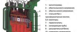
There are many options for connecting the transformer windings in a star, some of them are shown in the figure below. And, as they say, not all of them are equally useful, or rather, different connection diagrams are needed for different cases.
It should be noted that either one three-phase transformer or three single-phase ones can be connected into a star. The figure indicates:
- A, B, C – the beginning of the high voltage windings
- X, Y, Z – ends of high voltage windings
- a, b, c – the beginning of the low voltage windings
- x, y, z – ends of low voltage windings
Load distribution between phases
So, we always strive to load the phases evenly, that is, to attach the same power to each of them. When lighting with incandescent lamps, it is enough to correctly distribute the lamps between the phases. With fluorescent lighting, one more condition must be met, namely: connect the lamps located nearby to different phases. This is explained as follows: fluorescent lamps light up and go out 100 times per second, as alternating current with a frequency of 50 Hz passes through zero 100 times per second. Although we do not notice these pulsations of light, they have a harmful effect on vision. If lamps connected to different phases are located nearby, they will go out and light up at the same time, which will significantly reduce the depth of change in the luminous flux.
In addition, a profound change in the light flux can distort the actual picture of the movement of objects. Let, for example, a rotating object have time to make a full number of revolutions during the time the lamp goes out. This means that with each successive lighting the object will be visible in the same position, that is, it will seem motionless. If a rotating object manages to make a little less than a full revolution during the extinction, it will seem that the rotation is happening in the opposite direction. In industrial environments where there are mechanisms with rotating parts, this is extremely dangerous.
Connection of transformer windings in a triangle
The triangle connection is so called because of its external resemblance to a triangle (seen in the figure).
When connected into a triangle, the following relations apply:
- linear currents are √3 times greater than phase currents
- line voltages are equal to phase voltages
The three secondary windings, when connected in a delta, are connected in series, thereby forming a closed circuit. There is no current in this circuit, since the EMF of the phases are shifted by 120 degrees and their sum at each moment of time is zero. Also, the current is zero if the following conditions are met: the EMF has a sinusoidal shape, the windings have the same number of turns.
Star and triangle in the question of third harmonics of transformers
In transformers, the triangle circuit is used, among other things, to obtain third harmonic currents, which are necessary to create a sinusoidal EMF of the secondary windings. In other words, to eliminate the third harmonic component in the magnetic flux.
To introduce third harmonics when connecting to a star, the neutral of the star is connected to the neutral of the generator, and the third harmonics begin to run along this path.
Connecting transformer windings in a zigzag
A zigzag connection is used when there is uneven load on the secondary loads. After the zigzag connection, the load is distributed more evenly across the phases and the magnetic flux of the transformer remains in balance despite the uneven load.
Consider the zigzag star connection of a three-phase power transformer. A schematic representation is shown in the figure.
The primary windings are connected in a star. Next, we divide each secondary winding in half. And then we connect as shown in the figure.
When connecting into a zigzag star, a larger number of turns will be required than with a simple star. Also, with this connection it is possible to obtain three voltage classes, for example 380-220-127V.
Bookmark or share with friends
Source: pomegerim.ru
How to connect a three-phase motor to 380?
When a three-phase electric motor is connected by a star, the beginnings of its stator windings are connected together at one point, and 3 phases of 380 Volt power supply are connected to the ends of the windings. When connected in a triangle, the stator windings are connected to each other in series.
Interesting materials:
What does an employee's personal file contain? What's in potatoes? What's in pumpkin seeds? What is contained in the seeds? What became the main content of the art of classicism? What caused Batu to return to Mongolia? What happened to Queen after Freddie's death? What happened to Lugansk in the Secrets of the Investigation? What is humanity? What is a hyperbole?
§ 79. Triangle connection
In addition to a star connection, generators, transformers, motors and other three-phase current consumers can be connected in a delta.
In Fig. 179 shows an uncoupled three-phase system. By combining the wires of an unconnected six-wire system in pairs and connecting the phases as indicated in the drawing, we move on to a three-phase three-wire system connected by a triangle.
Rice. 179. Uncoupled three-phase system
As can be seen from Fig. 180, the delta connection is made so that the end of phase A is connected to the beginning of phase B, the end of phase B is connected to the beginning of phase C, and the end of phase C is connected to the beginning of phase A. Line wires are connected to the phase connections.
Rice. 180. Connected three-phase delta-connected system
If the generator windings are connected by a triangle, then, as can be seen in Fig. 180, line voltage is created by each phase winding. For a delta-connected consumer, the line voltage is connected to the phase resistance terminals. Therefore, when connected by a triangle, the phase voltage is equal to the linear voltage:
Let us determine the relationship between phase and linear currents when connected by a triangle, if the load of the phases is the same in size and nature. We compose the current equations according to Kirchhoff’s first law for three nodal points A 1, B 1 and C 1 of the consumer:
From this it can be seen that the linear currents are equal to the geometric difference of the phase currents. With a symmetrical load, the phase currents are equal in magnitude and shifted one relative to the other by 120°. By subtracting the phase current vectors according to the resulting equations, we obtain linear currents (Fig. 181). The relationship between phase and line currents when connected in a triangle is shown in Fig. 182:
Rice. 181. Phase and line currents when connected by a triangle
Rice. 182. Dependence between phase and linear currents when connected by a triangle
Therefore, with a symmetrical delta-connected load, the line current is √3 times the phase current.
In Fig. 183 shows a vector diagram of currents and voltages for a uniform active-inductive load connected by a triangle. The diagram is constructed as follows. On the selected scale, we build an equilateral triangle of linear network voltages UAB, UBC AND UAC, which are equal to the phase voltages of the consumer. In the direction of the lag at angles φAB, φBC, φCA to the linear voltages UAB, U BC and UCA, we plot the phase current vectors IAB, IBC and ICA on a scale. Then, as stated earlier, we determine the line currents IA, IB and IC.
Rice. 183. Vector diagram of currents and voltages with a uniform load connected by a triangle
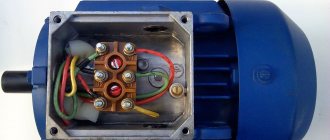
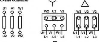
For motors and other consumers of three-phase current, in most cases, all six ends of the three windings are brought out, which, if desired, can be connected either by a star or a triangle. Usually a board made of insulating material (terminal board) is attached to a three-phase machine, to which all six ends are brought out.
Connection diagrams for triangle and star windings for dummies.
The most common question for those beginning to study the design of transformers or other electrical devices is “What are star and triangle?” We will try to explain in our article how they differ and how they are structured.
Let's consider the winding connection diagrams using the example of a three-phase transformer. In its structure, it has a magnetic circuit consisting of three rods. Each rod has two windings - primary and secondary. High voltage is applied to the primary, and low voltage is removed from the secondary and goes to the consumer. In the symbol, the connection diagram is indicated by a fraction (for example, Y⁄∆ or Y/D or U/D), the numerator value is the connection of the high voltage (HV) winding, and the denominator value is the low voltage (LV).
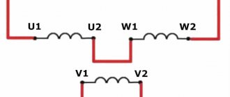
Each rod has both a primary winding and a secondary winding (three primary and three secondary windings). Each winding has a beginning and an end. The windings can be connected to each other using a star or delta method. For clarity, let us denote the above schematically (Fig. 1)
When connected by a star, the ends of the windings are connected together, and three phases go from the beginning to the consumer. From the terminal connections of the ends of the windings, the neutral wire N (also known as neutral) is removed. The result is a four-wire, three-phase system, which is often found along overhead power lines (Fig. 2)
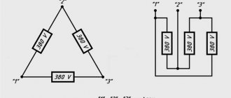
The advantages of this connection scheme are that we can get 2 types of voltage: phase (phase + neutral) and linear. In such a connection, the linear voltage is √3 times greater than the phase voltage. Knowing that the phase voltage gives us 220V, multiplying it by √3 = 1.73, we get approximately 380V - linear voltage. But as for the electric current, in this case the phase current is equal to the linear one, because Both linear and phase currents leave the winding in the same way, and it has no other path. It is also worth noting that only in the star connection there is a neutral wire, which is a load “equalizer” so that the voltage does not change or jump.
Let us now consider the connection of the windings with a triangle. If we connect the end of phase A to the beginning of phase B, connect the end of phase B to the beginning of phase C, and connect the end of phase C to the beginning of phase A, we will get a triangle winding connection diagram. Those. in this circuit the windings are connected in series. (Fig. 3)
Basically, this connection scheme is used for symmetrical loads, where the load does not change between phases. In such a connection, the phase voltage is equal to the linear voltage, but the electric current, on the contrary, is different in such a circuit. The linear current is √3 times greater than the phase current. The delta connection of the winding provides ampere-turn balance for zero current
sequences. In simple terms, the delta connection circuit provides balanced voltage.
Let's summarize. For a basic definition of power transformer winding connection diagrams, it is necessary to understand that the difference between these connections is that in a star, all three windings are connected together by one end of each winding at one (neutral) point, and in a triangle, the windings are connected in series. The star connection allows us to create two types of voltage: linear (380V) and phase (220V), and in a triangle only 380V.
The choice of winding connection diagram depends on a number of reasons:
- Transformer power circuits
- Transformer power
- Voltage level
- Load asymmetry
- Economic considerations
For example, for networks with a voltage of 35 kV and more, it is more profitable to connect the transformer winding with a star circuit, grounding the zero point. In this case, it turns out that the voltage of the transformer terminals and transmission line wires relative to the ground will always be √3 times less than linear, which will lead to a reduction in the cost of insulation.
In practice, the following groups of compounds are most often encountered: Y/Y, D/Y, Y/D.
The group of winding connections Y/Y (star/star) is most often used in low-power transformers that supply symmetrical three-phase electrical appliances/receivers. It is also sometimes used in high-power circuits when grounding of the neutral point is required.
The winding connection group D/Y (delta/star) is used mainly in high-power step-down transformers. Most often, transformers with such a connection operate as part of power supply systems for low-voltage current distribution networks. Typically, the star's neutral point is grounded to accommodate both line-to-line and phase-to-phase voltages.
The Y/D (star/delta) winding connection group is mainly used in the main transformers of large power stations and non-distribution substations.
Source: www.forwardenergo.ru