In household appliances, hand-held power tools, automotive electrical equipment and automation systems, a commutator AC motor is often used, the connection diagram of which, as well as the device, are similar to DC motors.
Their widespread use is explained by their compactness, low weight, low cost and ease of operation. In this segment, motors with high frequency and low power are most in demand.
Design features and principle of operation
In fact, a commutator motor is a rather specific device that has all the advantages of a DC machine and, therefore, has similar characteristics.
The difference between these motors is that the stator housing of the AC motor is made from separate sheets of electrical steel to reduce eddy current losses. The excitation windings of the machine are connected in series to optimize operation in a 220V household network. They can be either single- or three-phase; due to the ability to operate on direct and alternating current, they are also called universal. In addition to the stator and rotor, the design includes a brush-commutator mechanism and a tachogenerator. The rotation of the rotor in a commutator motor occurs as a result of the interaction of the armature current and the magnetic flux of the field winding. Through the brushes, current is supplied to a commutator assembled from trapezoidal plates and is one of the rotor units connected in series to the stator windings.
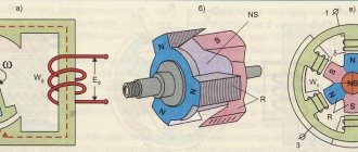
In general, the principle of operation of a commutator motor can be clearly demonstrated using the experiment known from school with the rotation of a frame placed between the poles of a magnetic field. If current flows through the frame, it begins to rotate under the influence of dynamic forces. The direction of movement of the frame does not change when the direction of current movement in it changes.
Connecting the field windings in series gives a large maximum torque, but high idle speeds appear, which can lead to premature failure of the mechanism.
Basic parameters of a DC motor
Torque constant
For a DC commutator motor, the torque constant is determined by the formula:
,
- where Z is the total number of conductors,
- Ф – magnetic flux, Wb [1]
see also
Basic parameters of a DC motor
Key Parameters of DC Motor
- Torque constant
- Constant EMF
- Motor constant
- Mechanical Rigidity
- Motor voltage
- Mechanical time constant
Basic parameters of the electric motor
General parameters for all electric motors
- Motor torque
- Motor power
- Efficiency
- Rated speed
- Rotor moment of inertia
- Rated voltage
- Electrical time constant
- T.Kenyo, S.Nagamori. DC motors with permanent magnets: Per. from English-M.: Energoatomizdat, 1989.
- GOST 27471-87 Electric rotating machines. Terms and Definitions.
- M.M. Katsman. Electrical machines and electric drive of automatic devices: Textbook for electrical engineering specialties of technical schools. - M.: Vyssh. school, 1987.
- L.M.Piotrovsky. Electric cars. Textbook for students of electrical engineering, energy and electrical technical schools.-L.: Energy, 1972.
- Microchip. Brushed DC motor basics.
Bibliography
Simplified connection diagram
A typical connection diagram can include up to ten output contacts on a terminal strip. The current from phase L flows to one of the brushes, then is transmitted to the commutator and armature winding, after which the second brush and jumper pass to the stator windings and exits to neutral N. This connection method does not provide for motor reversal due to the fact that series connection of the windings leads to simultaneous replacement of the poles of magnetic fields and as a result the moment always has one direction.
The direction of rotation in this case can be changed only by swapping the positions of the winding outputs on the contact strip. The motor is switched on “directly” only with the stator and rotor leads connected (via a brush-commutator mechanism). The output of half the winding is used to turn on the second speed. It should be remembered that with this connection the motor operates at full power from the moment it is turned on, so it can be operated for no more than 15 seconds.
Types of CD
It is customary to classify these devices according to the type of power supply; depending on this, two groups of CDs are distinguished:
- Direct current. Such machines are characterized by high starting torque, smooth speed control and a relatively simple design.
- Universal. They can operate from both constant and variable power sources. They are distinguished by their compact size, low cost and ease of management.
The first ones are divided into two subtypes; depending on the organization of the inductor, it can be on permanent magnets or special excitation coils. They serve to create the magnetic flux necessary to generate torque. CDs, where excitation coils are used, are distinguished by types of windings, they can be:
- independent;
- parallel;
- consistent;
- mixed.
Having dealt with the types, let's consider each of them.
Universal type CD
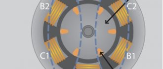
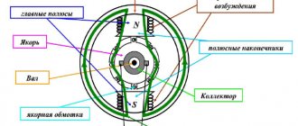
The figure below shows the appearance of an electric machine of this type and its main structural elements. This design is typical for almost all CDs.
Design of a universal commutator motor
Designations:
- A is a mechanical commutator, it is also called a collector, its functions were described above.
- B – brush holders, used to attach brushes (usually made of graphite), through which voltage is supplied to the armature windings.
- C – Stator core (made up of plates, the material for which is electrical steel).
- D – Stator windings, this unit belongs to the excitation system (inductor).
- E – Armature shaft.
For devices of this type, excitation can be serial or parallel, but since the latter option is not currently produced, we will not consider it. As for universal sequential excitation CDs, a typical diagram of such electric machines is presented below.
Scheme of a universal commutator motor
A universal CD can operate on alternating voltage due to the fact that when the polarity changes, the current in the field and armature windings also changes direction. As a result of this, the torque does not change its direction.
Features and scope of universal CDs
The main disadvantages of this device appear when it is connected to AC voltage sources, which is reflected in the following:
- decrease in efficiency;
- increased sparking in the brush-collector unit, and as a result, its rapid wear.
Previously, CDs were widely used in many household electrical appliances (tools, washing machines, vacuum cleaners, etc.). At the moment, manufacturers have practically stopped using this type of motor, giving preference to brushless electric machines.
Now let's look at collector electric machines operating from constant voltage sources.
CD with permanent magnet inductor
Structurally, such electric machines differ from universal ones in that permanent magnets are used instead of excitation coils.
Design of a permanent magnet commutator motor and its diagram
This type of CD is most widespread compared to other electric machines of this type. This is due to the low cost due to the simplicity of the design, simple control of the rotation speed (depending on voltage) and changing its direction (it is enough to change the polarity). The motor power directly depends on the field strength created by the permanent magnets, which introduces certain restrictions.
The main area of application is low-power drives for various equipment, often used in children's toys.
CD on permanent magnets from a toy from the times of the USSR
The advantages include the following qualities:
- high torque even at low speed;
- dynamic management;
- low cost.
Main disadvantages:
- low power;
- magnets lose their properties due to overheating or over time.
To eliminate one of the main disadvantages of these devices (magnet aging), special windings are used in the excitation system; let’s move on to considering such CDs.
Independent and parallel field coils
The first received this name due to the fact that the windings of the inductor and armature are not connected to each other and are powered separately (see A in Fig. 6).
Figure 6. CD circuits with independent (A) and parallel (B) excitation windings
The peculiarity of this connection is that the power supply U and UK must be different, otherwise a moment of force will arise. If it is impossible to organize such conditions, then the armature and inductor coils are connected in parallel (see B in Fig. 6). Both types of CD have the same characteristics; we found it possible to combine them in one section.
The torque of such electric machines is high at low speed and decreases as it increases. It is characteristic that the armature and coil currents are independent, and the total current is the sum of the currents passing through these windings. As a result of this, when the excitation coil current drops to 0, the CD is likely to fail.
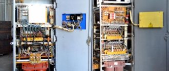
Engine control
In practice, engines are used with various methods of regulating operation. The commutator motor can be controlled using an electronic circuit in which the role of a regulating element is played by a triac, which “passes” a given voltage to the motor. A triac works like a fast-acting switch, the gate of which receives control pulses and opens it at a given moment.
In circuits using a triac, an operating principle based on full-wave phase control is implemented, in which the amount of voltage supplied to the motor is tied to the pulses arriving at the control electrode. The frequency of rotation of the armature is directly proportional to the voltage applied to the windings. The operating principle of the commutator motor control circuit is simplistically described by the following points:
- the electronic circuit sends a signal to the triac gate,
- the shutter opens, current flows through the stator windings, giving rotation to the motor armature M,
- the tachogenerator converts instantaneous rotation speed values into electrical signals, resulting in feedback with control pulses,
- as a result, the rotor rotates evenly under any load,
- Reversing the electric motor is carried out using relays R1 and R
In addition to the triac, there is a phase-pulse thyristor control circuit.
Braking methods
Electric motors in electric drives are designed to quickly stop production mechanisms or at least maintain the speed at a certain moment of the machines. Then the motor will contact the generator and operate in braking mode. When there is a need to quickly stop a machine device, they use braking of electric drives by switching the winding of the electric motor phases to obtain a field movement in the opposite direction.
Commutator motor braking circuit
In constant voltage motors, in order to implement counter-switching braking, you need to change the connection of the ends of the armature winding. In this case, the energy in the anchors and the moments will change their direction. The operating voltage will become greater, so in order to limit torque and energy, switch simultaneously by turning on resistors in the armature or rotor circuit. What happens to the braking energy? It will dissipate in the resistor and armature winding. Dynamic braking can be characterized by generators that dissipate energy in the braking resistor and the winding of the electric motor.
Ways to force stop devices:
- combined;
- electric;
- mechanical.
Electric motors are braked when it is necessary to fix the mechanism in a certain position and reduce the free run-down time. Mechanical devices are brake pulleys that are mounted on shafts with shoes. When the device is turned off, the pads will be pressed against the pulleys. Thanks to friction, kinetic energy will be converted into thermal energy, and braking will occur.
How does electric braking of an electric drive occur?
To quickly stop the device or ensure a constant speed of movement, an electric stopping method is also used. It all depends on the scheme for switching on the braking modes. They are regenerative, dynamic and anti-switching. When it is necessary to quickly stop the mechanism, they resort to the last method, when the polarity on the armature windings of the motors is changed while switching 2 phases to the windings of asynchronous electric mechanisms. When the windings are switched, a higher voltage will occur. To limit it, several additional resistors need to be installed in the stator and rotor windings. It is they who will limit the energy in winding during braking.
On asynchronous models connected to a network with non-constant current, a dynamic stop of the electric drive is used, which consists of disconnecting the winding from the network and applying a constant voltage. to the stator. During this, the rotors look like a squirrel cage. Due to constant voltage, stationary magnetic fluxes are created. When the rotor rotates, the electric motor can switch to generator mode. A braking torque is created. When the mechanism stops, the DC voltage will be turned off.
Regarding regenerative braking of electric vehicles
- During this, the motor is switched to generator mode, and the energy that is generated will be returned to the network or used to recharge the battery. Most often, these modes are found in the following types of transport:
- by train;
- electric locomotive;
- trolleybus;
- tram.
When braking occurs, the energy that is generated will be returned to the power grid. This mode is often used to recharge hybrid electric vehicles, electric bicycles, and electric scooters. This mode is the most economical. It is used when the rotor speed exceeds the idle speed.
Regenerative braking of a commutator electric motor
Types of electric motors
All electric motors have their own distinctive features. They can be explained by the scope of using motors where it is beneficial. For example, some engines are installed in vacuum cleaners, and others are installed in fans. Each of them has some distinctive properties. Collector, brushless, asynchronous, direct current, switched inductor - I would like to bring each of them to perfection.
Advantages and disadvantages
The undeniable advantages of such machines include:
- compact dimensions,
- increased starting torque, “versatility”, operation on alternating and direct voltage,
- speed and independence from network frequency,
- soft adjustment of speed over a wide range by varying the supply voltage.
The disadvantage of these engines is considered to be the use of a brush-commutator junction, which causes:
- decreased durability of the mechanism,
- sparking between the commutator and brushes,
- increased noise level,
- a large number of collector elements.
Typical faults
The brush-commutator mechanism requires the greatest attention, in which sparking is observed even when the new engine is running. Worn out brushes should be replaced to prevent more serious problems: overheating of the commutator lamellas, their deformation and peeling. In addition, an interturn short circuit of the armature or stator windings may occur, which results in a significant drop in the magnetic field or strong sparking of the commutator-brush junction.
Premature failure of a universal commutator motor can be avoided by proper operation of the device and the professionalism of the manufacturer during the assembly process of the product.
Characteristics of a brushed DC motor
The operational properties of DC motors are determined by their operating, electromechanical and mechanical characteristics, as well as control properties.
Mechanical characteristics of brushed DC motors