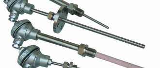
This electrical device was invented by the German physicist Poggendorff in the second half of the 19th century. The first sample of the device gave a clear idea of what a rheostat (RS) is. Its purpose was to influence the amount of current and voltage in an electrical circuit by changing its own resistance.
a) – slider rheostat, where B – input, A – output of electric current; b) – schematic representation of the RS
How does a rheostat work?
A rheostat is a controlled variable resistance that can change the current parameters in an electrical circuit.
As a result of a large number of experiments and scientific and technical research, various models of rheostats appeared, such as:
- wire;
- slider;
- liquid;
- lamp.
Wire
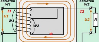
This is the simplest rheostat. It consisted of high resistivity wire stretched over a frame. It passed through several connectors at once. By switching on one or another contact, they achieved a change in the length of the conductor. Thus, the required resistance value was obtained, therefore, the parameters of current and voltage in the electrical circuit were changed. The disadvantage of such a device was the limited length of the conductor and, accordingly, the range of changes in current characteristics.
Slider
A slider device is a classic rheostat design. RS is an elongated coil that looks like a cylinder of dielectric material with a wire wound on it, covered with scale. A slider moves progressively along the rod, which touches the coil spiral with its contacts. The device is connected to the electrical circuit at two points: this is the contact of the slider and one of the ends of the coil.
Liquid
The device is a container filled with electrolyte, into which two electrodes in the form of metal plates are immersed. The resistance of the current flowing through the electrolyte depends directly on the gap between the electrodes and is inversely proportional to the surface area of the electrodes.
Lamp
The resistance in the circuit is regulated by the number of incandescent lamps connected in parallel. This is not a very good solution. Adjusting current parameters is expensive due to the large waste of electricity consumed by incandescent lamps.
Important! All of the above devices are long gone, except for the slider rheostat. They were pioneers in the field of adjusting electrical current parameters. They were replaced by economical and compact variable resistors. Despite this, the principle of operation of the devices remains the same.
solution of the problem
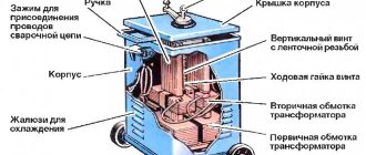
Rheostat with a continuous change in resistance An example of a rheostat with an almost continuous change in resistance is shown in Fig. You just need to hold back all the excess electricity with a rheostat with a sufficiently high resistance. Metal rheostats with oil cooling provide an increase in heat capacity and heating time constant due to the high heat capacity and good thermal conductivity of the oil. These contacts became widespread.
The rheostat consists of a number of identical resistance 9 sections connected to 8 contacts. It acts as a rheostat with high resistance and takes on almost the entire load.
Several circuits with one or two resistances can be used here. Disadvantages: relatively low switching power and low breaking power, high brush wear due to sliding friction and melting, difficulty in using for complex connection schemes. Oil-cooled devices increase heat capacity and heating time due to the good thermal conductivity of the oil.
The total resistance of the circuit consists of the resistance Rl of the light bulb and the resistance of the part of the wire included in the circuit in the figure, shaded by the rheostat.
The total resistance of the circuit consists of the resistance Rl of the light bulb and the resistance of the part of the wire included in the circuit in the figure, shaded by the rheostat.
Let's figure out how contact is made between the turns of the winding and the slider. Lesson 8. RESISTOR - RESISTANCE
Principle of operation
The principle of operation of the PC can be considered using the example of the operation of a slider device. The slider moves along the coil across the winding turns. On the sides of the ceramic cylinder there are two posts that support the horizontal rod. The slider is put through a hole in the housing onto this horizontal axis, along which it moves freely.
What is potential in electricity
The slider rubs against the coil turns with two metal plates. Current cannot pass directly through the turns, but only in a spiral. Consequently, only that part of the coil that is located between the input contact and the slider can work. This solved the problem of limited length of the wire RS conductor.
The closer the contactor is to the input contact of the coil, the lower the resistance of the PC. As a result, the voltage decreases and the current in the electrical circuit increases. Voltage is applied to the entire length of the winding, and the operating current is removed by the contacts of the slider. The contactor basically divides the PC into two series-connected resistors.
Note! The rheostat in the diagram is designated as a rectangle with an arrow. The geometric shape is a reel, and the arrow represents a slider.
Rheostat designation on the electrical circuit
Operating principle
The operating principle of all rheostats is similar. The slider rheostat has the simplest design and visually clear principle of operation. It is connected to the circuit through the lower and upper terminals. The design is made in such a way that the current does not pass across the turns, but through the entire length of the wire selected by the slider. This occurs due to reliable insulation between the conductors.
The rheostat has the ability to operate in potentiometer mode. To do this, when making a connection, you must use all three terminals. The bottom two are used as an entrance. They are connected to a voltage source. The top and one of the bottom terminals are output. When you move the slider, the voltage between them is adjusted.
Rheostat used as a voltage divider
In addition to the potentiometer, a ballast mode of operation of the rheostat is also possible, when it is necessary to create an active load for energy consumption. In this case, it is necessary to take into account what scattering abilities the device has. Excessive heat can damage the device, so it is recommended to connect the rheostat to the network, having previously calculated the power dissipation and, if necessary, ensure sufficient cooling.
Types of rheostats
Ammeter - what is it and the design of the device
The main three types of rheostats:
- toroidal rheostat;
- lever type;
- plug RS.
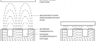
Toroidal rheostat
The PC winding is a toroidal structure, the upper surface of which forms a contact track. The rotary contactor rotates around its axis, touching the winding. The toroidal coil ensures continuity of the electrical circuit during rotation of the slider.
This feature of variable resistance is used in urban electric transport. Continuous changes in current and supply voltage of the electric motor ensure smooth movement of the vehicle. If the device breaks down, it cannot be repaired. The device will need to be replaced with a new rheostat.
Toroidal rheostat
Lever type
Unlike the toroidal model, a lever rheostat changes the value of current resistance in jerks. The lever, acting as a contactor, moves from one contact to another. The device contains several resistor lines with a certain resistance. The lever slider simultaneously operates as a switch on one line and a switch on another resistor.
Plug-in PCs
Like the lever type PC, plug devices regulate the resistance of the electrical circuit in steps. The only difference is that the transition from one mode to other current parameters occurs without breaking the circuit. When the next plug is removed, the energy flow is redirected through a certain resistor.
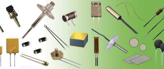
Classification of resistors
Resistors differ not only in their ability to adjust resistance. They can be made from different resistive materials, have different numbers of contacts, and have other features.
By type of resistive material
The elements can be wire, non-wire or metal foil. High-resistance wire is a feature of a wire element; alloys such as nichrome, constantan or nickel are used for its manufacture. Films with increased resistivity are the basis of non-wire elements. Metal foils use special foil. Now let's find out what resistors are made of.
Semiconductor design
Non-wire are divided into thin-layer and composite, the thickness of the former is measured in nanometers, and the latter in fractions of a millimeter. Thin-layers are divided into:
- metal oxide;
- metallized;
- borocarbons;
- metal-dielectric;
- carbonaceous.
Composite ones, in turn, are divided into volumetric and film. The latter can be with an organic or inorganic dielectric. To understand whether a resistor has polarity, you should know that their sides are identical.
By purpose resistance
Permanent and variable semiconductors also have some differences in characteristics. Permanent ones are divided into general and special purpose conductors. The latter may be:
- high frequency;
- high voltage;
- high-megaohm;
- precision.
Such parts are used in precision measuring instruments; they are particularly stable.
Variable resistors can be divided into trimming and adjusting. The latter can be with a linear or nonlinear functional characteristic.
By number of contacts
Depending on the purpose of the resistor, it may have one, two or more contacts. The contacts themselves are also different, for example, for SMD resistors it is a contact pad, for wire resistors it is a special wire composition. There are metal film resistors with quantum point contacts, and in variables they are moving.
Different number of contacts on elements
Other
Resistors differ in the shape and type of resistance, as well as in the nature of the dependence of the resistance value on voltage. The description of the dependence of a quantity can be linear or nonlinear. Using the element is simple, the capacity is indicated on the body, minus and plus are the same.
Resistors may or may not be sealed against moisture, and the housing may be varnished, vacuum sealed, sealed, pressed into plastic, or compounded. Nonlinear ones are divided into:
- varistors;
- magnetoresistors;
- photoresistors;
- posistors;
- strain gauges;
- thermistors.
They all perform their specific function, some change resistance based on temperature, others on voltage, and others on radiant energy.
Manufacturing materials
What is a throttle
Rheostats are divided into 4 types based on the type of material they are made of. These are carbon, metal, liquid and ceramic RS:
- Carbon devices include models where a graphite rod acts as a variable resistance.
- A metal example of execution can be slider rheostats. They have a variable resistor - a coil of metal wire.
- Liquid variable resistances are used to control the operation of electric motors in explosive atmospheres.
- Ceramic rheostats include toroidal devices. Their device is described above in the text.
Design features
Rheostats are divided according to the material of manufacture:
- metal, which are most widespread;
- ceramic, most often used at low power;
- coal, still used in industry;
- liquid, providing the smoothest possible control.
Heat removal can be either air, water or oil. Liquid cooling is used when it is impossible to dissipate heat from the surface of the resistor. To increase heat transfer, a radiator with a fan can be used.
Cooling
Electricity, passing through a resistor, spends part of the energy to overcome the resistance of the conductor, which is converted into heat. If it is released excessively, the rheostat can overheat and become completely unusable.
For this reason, according to GOST, two cooling systems for variable resistors are used, these are:
- air;
- liquid.
Air cooling system
It is based on forced ventilation. For this purpose, blade and turbine fans are used. In a rheostat, the sensor measures the heating level of the device. When the permissible temperature threshold is reached, the sensor sends a signal to turn on the ventilation system. When the temperature drops, the fan turns off.
Liquid cooling
Liquid cooling of a high-power variable resistor is carried out using a sarcophagus, in the jacket of which mineral oil constantly circulates. It removes heat from the rheostat to the outside.
Where and for what are voltage dividers used?
PTs normalize voltage; more often they are used to adjust application parameters (serviced equipment) within the normal values for which it is designed, when such a function is built into it, for example, sound volume, fan speed. The most common model is with manual adjustment, but there is also an automatic integrated potentiometer.
PT is also used when it is necessary to establish the desired mode of equipment in difficult conditions, when a certain level of electrical parameters can disable the application, or for research, for the purposes of maintenance, repair, experiments, and adjustment.
An increase/decrease in U supplied to the load, which also entails changes in current, is carried out by potentiometers or rheostats. We will look at the difference between them below. In fact, these terms do not denote the part itself (in all cases this is a variable resistor), but the modes of its inclusion in the circuit.
The most typical examples of what is regulated:
- power and other parameters (adjustment by equalizers) of sound, video brightness/shades, light (dimmers);
- speed of low-power electric motors of household appliances and toys;
- Fans with variable speed settings have voltage dividers. Even those whose rotation intensity is meant to be set to constant operation with a certain value? often have a trimmer on the chip;
- generator frequency;
- calibration of electrical circuits, on microcircuits for adjusting electrical parameters by voltage (its output power).
- Precision, including automatic high-precision potentiometer is used in angular and linear displacement sensors.
Variables/trimmers are used wherever adjustment of the output voltage is required. But you need to understand that such a device is needed only for high-resistance loads and low currents. Where these parameters are large, rheostats are used. For example, the dimmer may contain a DC, but if the incandescent lamp is powerful, then it will be useless and a PC must be used. The same applies to electric motors: low-power ones can be regulated by PT, but powerful power plants in vehicles have RS. In order to study where to apply what, you need to do calculations using Ohm's formulas.
Why do you need a PC?
Based on what a rheostat is needed for, variable devices are divided into the following types:
- ballasts;
- launch RS;
- ballasts;
- load devices.
Ballasts
Rheostats are used in the control system of DC electric motors. With alternating current, the RS is included in the power supply circuit of asynchronous motors with a phase rotor.
Launcher PCs
Their main purpose is to reduce the inrush current during the start of the electric motor. Also, such rheostats work in regenerative rheostatic braking systems. It is needed to smoothly reduce the rotation speed of the rotors of electric motors and generators.
Ballasters
Ballast DCs quickly absorb the energy that is released during sudden braking of the electric motor. That is, ballast is discharged in the form of excess electricity.
Load devices
PCs of this type create additional load in the electrical circuit. This is necessary to maintain the necessary processes associated with the operating mode of various devices, engines and other devices.
Potentiometer connection
To begin with, we present a block of the most typical schemes. It must be said that the PT can be connected not only as a PC, but also as a simple fixed resistor (options in Fig. 3):
Below are the most common schemes (notations according to Western standards):
It must be said that the traditional wiring diagram for a potentiometer frequency switch always recommends connecting an “extra” pin; a break in the “moving contact - horseshoe” line is not excluded, which can lead to unpleasant consequences.
The diagrams for how to connect a PT are extremely simple; in fact, there is only one option - in parallel to one of the power wires.
For example, this is what the regulator on a computer cooler looks like. In this case, polarity does not matter. Take any cooler power supply wire, cut it, one end is soldered immediately to the first and second (middle) contacts, the second to the remaining one. That is, on the first 2 contacts there is one end of the wire (they are soldered to the same conductor), the third contact is the other end, as if standing alone.
The complexity of some circuits: you need to know which wire to connect to, that is, which power line to regulate, for example, if you are connecting an external potentiometer for variable-frequency electric drives to adjust the intensity of rotation of electric motors, when adjusting PID controllers.
In such cases, they are guided by the schemes of the manufacturers or authors of such improvements, the recommendations of the masters; all the information is available online on special forums and thematic sites. Below is an example of connecting to a frequency converter:
Rheostat-based sensors
The position of the slider in the PC determines the magnitude of voltage and current in the operating electric current circuit. Making a sensor based on a rheostat is not difficult. The phase and zero of the power supply are supplied to the toroidal variable resistance, and the changed phase from the resistor and zero are output.
Today, outdated devices have been replaced by optical and magnetic analogues. Sensors based on variable resistors continue to be widely used in radio engineering. These are tuning resistances for volume controls and other options.
Rheostat based sensor
By turning the volume control knob of the radio device, move the slider along the graphite disk. The resistance of the circuit and the power of the sound signal depend on its position.
Variable resistor.
A variable resistor is a resistor in which the electrical resistance between the moving contact and the terminals of the resistive element can be changed mechanically.
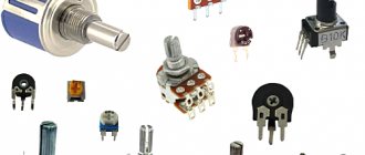
Variable resistors, also called rheostats or potentiometers, are designed to gradually regulate current and voltage. They look like this:
The difference is that a rheostat regulates the current in an electrical circuit, and a potentiometer regulates voltage. On radio circuits, variable resistors are designated by a rectangle with an arrow attached to their body.
In the diagrams, numbers 1 to 3 indicate the location of the resistor outputs.
You can adjust the resistance power of variable resistors by rotating a special knob. Those resistors in which the resistance of the resistor can be adjusted only with a screwdriver or a special hex key are called tuning variable resistors. They look like this:
Rheostat for car interior heating stove
The car's heater itself, when turned on, is at a static heating level. The level of air temperature in the cabin depends on the speed of rotation of the fan rotor. A rheostat built into the fan power circuit changes the speed of the hot air flow through manual control.
There are combined systems for heating the car interior. This is when the degree of heating of the air flow is regulated by two rheostats: the stove itself and the fan.
Car heater rheostat
Additional Information. A typical cause of failure of the interior heating system is often a blown fuse. The breakdown is eliminated by re-soldering the electrical part.
With the development of scientific and technological progress, many electrical appliances quickly become obsolete. They are being replaced by more advanced devices, less expensive and more efficient. The same thing happens with rheostats. The electrical industry is constantly supplying the market with newer and more advanced types of resistors.
Examination
Checking the potentimeter is done with a multimeter:
- the resistance measurement mode is set, the probes touch the two outer contacts - the tester should show a value equal to the nominal one with a permissible deviation. Move the slider and observe how R changes on the multimeter display;
- the wire winding may be torn, the contacts may come loose - then the break is checked as standard - the tester is set to “continuity”, the two outer contacts are touched with probes: 1 - break; 0, digital values tending to it or beeping (if there is a buzzer) - the circuit is intact.
Repair
If a contact falls off, it can be soldered, but this is usually difficult to do, much less it is impossible to repair a mechanically damaged track or wire. In case of such breakdowns of functional parts, especially the resistive segment, the variables are not repaired.
If the functional parts are without mechanical damage, then you can try the following methods:
- restore the sensitive track: o lightly bend the spring of the movable contact with the lead of a simple pencil (consists of carbon) and draw along the sensitive layer. Method for thin film models;
- o grind the same stylus, mix with lithol or a similar lubricant, lubricate the path along which the slider walks;