Let's figure out why voltage appears on the neutral wire, what the danger is and what should be done to prevent possible troubles and consequences.
Let's immediately turn to the diagram (Fig. 1) and determine the main reason for the appearance of voltage where, by definition, it should not be.
To do this, let’s slightly modify the drawing (Fig. 2) and consider the distribution of potentials in different parts of the electrical circuit. In this case, we take a single-phase circuit, as is done in apartments and most private houses.
The ground is the point of zero potential, the phase is a voltage source of 220 Volts, the current flows from the phase through the consumer to zero, then to the ground.
In the context of this article, by voltage we will understand the potential difference (as expected) between the points under consideration (1 or 2) and the exact zero potential (0).
So, the neutral wire from the consumer to the transformer substation has a resistance Rn. By the way, the higher the current (more powerful the load), the higher the voltage drop, which means the potential at point 2 is higher.
Another thing is that under normal conditions (no faults and good connections) this value is small. For example, with a total resistance of the neutral wire of 1 Ohm at a current of 1 Ampere, the voltage drop will be 1 V.
That is, at point 2 we will have 1 Volt, which, in principle, is not much. I'm simplifying things here because the goal is to demonstrate why voltage appears on the neutral wire, and not to estimate its exact value.
If for some reason our resistance Rn increases, for example due to a broken contact somewhere, then the potential at the point in question increases. Visually, this will be manifested by a decrease in the brightness of the lamps in the apartment, the cessation or deterioration of the operation of household electrical appliances.
By the way, if you touch this place, you can receive a sensitive electric shock, since the resistance of your body Radd (Fig. 3) will create a path for the flow of part of the current determined by your resistance and voltage at point 2. For values of 2 kOhm and 50 Volts, respectively, this value will be 25 milliamps.
What kind of lighting do you prefer?
Built-in Chandelier
This is already unpleasant, especially considering that 100 mA is a deadly value.
At the point where the contact is broken, the neutral wire (as long as consumers are connected to the network) will heat up and this may end in a fire or burning out of the neutral. Let's move on to Figure 4.
In this case, the circuit opens, no current flows through the neutral wire and the potential at point 2 will be a full 220 Volts. The indicator screwdriver will show this, and touching this part can be fatal.
When a phase breaks down on the body of the device (if it is conductive), it will naturally have the same voltage.
By the way, a zero break can be caused by other reasons, for example, mechanical damage during repair and construction work. However, the question of why this happened is secondary, the main consequence that we have just considered.
Expert opinion
It-Technology, Electrical power and electronics specialist
Ask questions to the “Specialist for modernization of energy generation systems”
What is the difference between "zero" and "ground" if they are connected together? If your measurement results show the same voltage, the wiring is connected in violation of the Electrical Installation Rules. Ask, I'm in touch!
How to calculate line voltage?
Specialists use the Kirchhoff formula to calculate line voltage parameters:
Specialists use the Kirchhoff formula and Ohm's law to calculate the parameters of line voltage.
When an extensive system of supplying an object with electricity is being implemented, sometimes there is a need to calculate the voltage between two wires “zero” and “phase”: IF = IL, which indicates that the phase and linear parameters are equal. The relationship between phase wires and linear ones can be found using the formula:
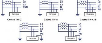
The use of three-phase lines in apartment buildings
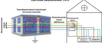
Not everyone knows that apartment buildings are also supplied with 380 V. This is what allows shops and various workshops to operate on the first or ground floors. In access switchboards, the three-phase circuit is distributed apartment by apartment, with the result that each of them has one phase and zero. It is they who provide the phase voltage of 220 V.
PHOTO: This is how a three-phase network is divided into three single-phase ones
If it is necessary to connect equipment in the apartment that requires a voltage of 380 V, the owner can submit an application to the management company. The specialist will determine the possibility of such a connection, after which it will be possible to install a three-phase line into the apartment, after first replacing the electricity meter with an appropriate one.
PHOTO: A three-phase electricity meter is much larger than a single-phase one
Short circuit and overload
What is the difference between these two phenomena - short circuit and overload?
In an electrical circuit, 4 fundamentally different modes can be distinguished, which differ in current consumption:
- Idle mode. The current is zero, the voltage is rated, there are no losses on the wires. An outlet to which nothing is connected acts as a voltage source in idle mode.
- Nominal mode. Otherwise - normal mode, when the load power does not exceed the design one. In this mode, everything is fine, we are quietly enjoying the benefit of electrification of the country. If there is a voltage drop, it will be insignificant - a few percent.
- Overload mode. In this mode, the current can slightly (tens of percent) or several times (hundreds of percent) exceed the rated current. Overload can occur due to partial deterioration of insulation, excess of the total power of connected consumers, or due to a malfunction inside a separate electrical appliance (for example, an interturn short circuit or a jammed electric motor, or a short circuit inside the heating element).
- Short circuit mode. This is the most severe, destructive mode with large heat release. The current at the fault point is the maximum possible for the given conditions. Other side effects of a short circuit are a decrease in voltage for other consumers (how new German refrigerators burned out in the regional Magnit warehouse due to low voltage) and phase asymmetry (what phase asymmetry (misalignment) leads to and how to protect against it).
That is, an overload differs from a short circuit in the magnitude of the overcurrent. During a short circuit, the current becomes the maximum possible at a given point in the circuit, and during an overload, the current value is greater than the rated value, but less than the short circuit current.
Any currents higher than the rated current are called overcurrent .
Due to an overload, a short circuit can easily occur - the wires heat up, the insulation melts, and so on, with all the ensuing, shooting and exploding consequences.
Do not confuse overload, short circuit and sparking (arc breakdown). If the first two concepts differ in the value of the overcurrent, then in the event of a sequential arc breakdown (for example, the tightening of a terminal in a socket is loose), the effective value of the current can be quite insignificant (units of amperes), which will not trigger either the circuit breaker or the RCD. Only an anti-sparking device (against arc breakdown), which is still relatively rare, can save the situation from a fire.
I have several articles on such devices on my blog, here is the last one for today.
How to determine zero and phase without instruments
According to the PUE (Electrical Installation Rules), each wire that has its own functional purpose has its own specific color marking:
- the phase wire has insulation in black, white, brown (the most commonly used) colors and their many shades;
- the neutral wire has blue insulation with any shades of it;
- the earth is insulated with yellow-green stripes.
If the regulations were strictly observed, then there would be no problems with determining where the phase is, where the zero is, and where the ground is. In order to make it easier to navigate switching diagrams, phase, zero and ground designations are introduced on many electrical devices. All conductors are designated in accordance with state standards:
- L - this Latin letter designates the phase;
- N - this sign is used to find the neutral wire;
- PE - this combination of letters has always denoted land.
However, the visual method has some subjectivity; it is not always possible to accurately determine the correct color of the conductor insulation. In addition, not all electricians adhere to regulatory documents when carrying out electrical installation work. In old buildings, there is no need to talk about any standards for color marking of wiring.
Therefore, this method of finding phase and zero without instruments exists with a high degree of conditionality; it does not have a 100% guarantee. However, it is the only real way among others, such as using raw potatoes, to determine phase and zero without instruments. To obtain a reliable result, it is better to use data on the compliance of the wires with phase, neutral or grounding, tested using an indicator screwdriver or a multimeter.
Why is there voltage between zero and ground. Why does the lamp glow between zero and ground?
Colleagues, tell me, what was it? Completely confused. I made a connection from the overhead line to the pipe stand for my father-in-law over the weekend. The air supply to the house already existed, but this house will be demolished, and for the new one and during the construction period they decided to connect an ASU in the yard on a pipe stand. Assembled the ASU and metering unit. We buried the grounding as required - hammered in three three-meter corners 50x50.
I decided to make the grounding system as it should be TN-CS with PEN splitting to the input circuit breaker - in the photo there is a large compression between PEN and grounding.
Before connecting, I decided to poke the control (60W incandescent lamp) and turned it on between phase and ground - it lights up brightly. I think very well - the land is good. And just in case, I turned on the lamp between the working zero and the ground and the lamp also lit up (see Diagram 1), but not at full strength, but quite noticeably - with a light orange glow, while I had not yet connected the ASU to the line, phase and zero for testing, I took from a carrier about 15 m long and a wire cross-section of 1.5 - 2.5 sq. mm (indicated in the diagram as R3), in the house, in addition to my extension cord, there was a load (R2) on, I don’t know what, I didn’t look, a couple of kilowatts it definitely was. I was surprised by the result and thought that grounding at the substation was useless. The overhead line is rustic, made of aluminum, the poles are mixed with wood and concrete, I didn’t find any repeated grounding on the poles along my street.
I decided to abandon TN-CS and make TT, so as not to be the only grounding for the entire block. When connecting, when the wires were cut off from the facade, I poked the cut-off SIP with the tester again, see diagram 2. the lamp between zero and ground stopped glowing!
Actually, this is the question - what was it? Why does control L1 light up when switched on according to scheme 1, but when the load is removed (scheme 2) the lamp does not light up? I'm stupid and can't understand. Tell.
PS: Assembled shield in conclusion. The black thing on the left is a heating element for heating. There wasn't enough space in the box; I had to place it on a metal corner.
Testing the two-phase model
The stator and many other structural elements of a two-phase electric motor have their own distinctive features, which determine the features of the test. The features of checking a two-phase electric motor include the following points:
- In this case, the resistance on the housing must be checked. A reading that is too low indicates that the stator needs to be rewinded.
- To obtain more accurate readings, it is recommended to use a megohmmeter, but such a measuring tool is extremely rare at home.
Before testing an electric motor, a visual inspection should be performed. Mechanical damage can lead to serious performance problems.
The switch is placed on phase or zero - All about electricity
Whether you are an expert or not, if you decide to change the electrical wiring in your home, even if it is in the “box - switch - light bulb” section, you should know the basic rules of the Electrical Installation Code (full decoding - “Electrical Installation Rules”, that is, a set of standards applicable to any electrical installations and electrical networks). It is from here that you can get information about whether the switch is going to zero or phase.
A phase is missing in the switch - what to do? — blog SamElectric.ru
How difficult it can be to light a light bulb
In the article I will consider in detail when and on which contacts of the switch there is a phase or zero. This knowledge is needed to quickly determine why the light bulb is not on. And what is faulty in this case - wiring, switch, socket, light bulb?
Background, real case.
The other day I received a call. They told me they needed an electrician, that they took my business card from an electrical store, and that the light in the bathroom didn't work.
The owner of the apartment with the same light bulb suggested that the problem was in the switch.
There could be several reasons for this - a burnt-out light bulb, no contact in the socket, a really broken switch, broken wires near the switch or lamp, no contact in the distribution box. It could have been worse, but I didn't think about it at the time.
Hoping for the best (maximum 5 minutes and minimum 300 rubles), I went to the challenge.
How lighting works in bathrooms
This apartment has aluminum wiring, which is a big minus. When opening the bathroom switch, it turned out that it was working properly and that the apartment was one of those cases where it was not done entirely correctly - the switch opens zero, not phase.
Why is this done? I have asked myself this question more than once. In my apartment, the switch also opens zero.
For safety reasons, it has always been a rule that the light switch must open a phase.
This is done so that when replacing a light bulb or wiping a chandelier, the likelihood of electric shock is minimal.
It is enough to turn off the switch - and you can safely change the lamp with your bare hands or even dig into the socket. Naturally, first check the absence of a phase with an indicator screwdriver.
So why didn't electricians in older houses (more precisely, in houses where aluminum wiring is used) adhere to this important and simple rule? It turns out that the wire was simply with colorless (more precisely, white) insulation, and no one bothered to distinguish phase from zero. Are the sockets working? Are the lights on? What else does? The phase was observed only in the panel on the site, when connecting the meter and circuit breakers
And then, not always.
If done according to the rules, the lighting must go through a separate power line, through a separate circuit breaker with a current of no more than 10A, and all connections must be made in the distribution box above the switch. The phase opening has already been discussed above.
What testing devices are there?
There are two ways to perform a phase check:
- straight. A method in which testing is carried out at the inputs of electrical appliances that are under operating voltage. It is usually used for devices up to 110 kV;
- indirect. A method in which the process is carried out using secondary electrical voltage. This test is usually performed in the presence of voltages of 110 kV and above.
Transformer phasing diagram with jumper installation. There are not many devices used in testing. Popular among them:
- voltmeters. Typically used in devices with voltages up to 1 kV. They connect directly to equipment terminals or parts of devices that conduct current. As for accuracy, it is not required from such devices;
- phase indicator. The sequence of phases and their order are determined by induction phase indicators. They consist of several coils, inside of which there are ferromagnetic cores and an aluminum disk. The principle of operation of the device is similar to the operation of an asynchronous type electric motor. When it is connected to a three-phase network, all coils begin to rotate the electromagnetic field around them. Because of this, the disk begins to rotate, which shows the phase sequence of the network.
You may be interested in this Features of casings for wires
The voltage between zero and ground is normal. What exactly and how to ground?
To put it very briefly and simply, there are two grounding systems that are relevant to us - TT and TN. The TT grounding system is a separate grounding rod at the house (an angle or a system of welded angles driven into the ground), which is connected directly to the earthing bus (PE) in the panel. Further, only the grounding conductors of the internal wiring cables extend from the bus.
Grounding electrodes
The TN grounding system is the same, only in addition to grounding the PE bus to the corner, it is directly grounded to the neutral wire from the power line main coming from the substation, grounded both at the transformer itself and on some power line supports.
Which system is better? Which one should I use?
Technical Circular No. 32/2012, in paragraphs 3 and 4, explains the requirement of the PUE clause 1.7.59 “Power supply of electrical installations with voltage up to 1 kV from a source with a solidly grounded neutral and with grounding of exposed conductive parts using a ground electrode not connected to the neutral (TT system) , is allowed only in cases where electrical safety conditions in the TN system cannot be ensured.”
According to the clarification of the circular, if the main line is laid with separate overhead uninsulated wires, it is considered unsafe for the implementation of the TN system (there is a high probability of a separate break of the neutral conductor, which leads to the appearance of dangerous voltage on the ground wire), and in this case it should be temporarily grounded using the TT system until reconstruction highways. In the case of a main line stretched with SIP wire, it is necessary to use only the TN system. You can argue with this, you don’t have to argue, but let’s still rely on some consolidated opinion, already embodied in at least some documents.
So, since in most villages the overhead lines have already been reconstructed and carried out by SIP, we will only be interested in the TN system.
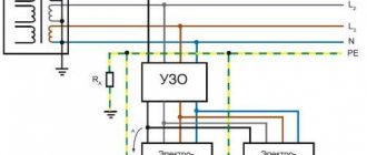
So, we found out that the grounding of a country house should be the following design. The main neutral conductor (the so-called combined neutral working and neutral protective conductor, PEN), grounded at the transformer and again at some overhead line poles, enters the home panel onto the PE grounding bus. This bus is grounded to the ground near the house (in fact, another so-called re-grounding of the PEN conductor). The same panel houses the zero bus (N). The PE and N buses are connected by a jumper (the so-called division of PEN into PE and N). All. Here you have both zero and grounding in the shield.
What is it measured in?
According to GOST 13109, the voltage standard in the electrical network varies in the range from 198V to 242V (that is, 220V plus or minus 10 percent). If household appliances, lamps often break down or flicker, you will need to measure the voltage in the electrical wiring. A similar check is done with a multimeter or voltmeter. At night, when electrical appliances are used to a minimum, the values obtained will be maximum.
A multimeter measures the voltage in a three-phase network as follows:
- Between working 0 and each of the phases: A-N, B-N, C-N.
- Linear voltages: A-B, A-C, B-C.
There should be six dimensions in total. Sometimes another measurement is made - between the grounding and neutral working conductor: N-PE.
What to do in case of high voltage
If there is a significant potential difference between the neutral and ground, then it is desirable, and in some cases necessary, to solve this problem. How to deal with this situation depends on what the voltage is between neutral and ground.
Conclusion
As can be seen from the article, there is almost always a small voltage between zero and ground. This is not a problem if it does not exceed 5-10 V. Otherwise, measures must be taken to ensure that this phenomenon does not damage electrical appliances or interfere with their use. Depending on its value, you need to install a voltage stabilizer, disconnect the built-in filter in household appliances, or turn off the input circuit breaker and eliminate the fault.
Source
The difference between line voltage and phase voltage
Before considering the practical meaning of these parameters, it is necessary to know exactly how linear and phase voltages differ from each other. A certain phase-to-phase voltage in a three-phase circuit can occur either between two phases or between one of the phases and the neutral wire. Such interaction becomes possible due to the use of a four-wire, three-phase circuit in the circuit. Its main characteristics are voltage and frequency.
The voltage that occurs between two phase conductors is considered linear, and between the phase and zero conductors, a phase voltage occurs. Line voltage is used to calculate currents and other parameters of a three-phase circuit. To such circuits it is possible to connect not only three-phase contacts, but also single-phase ones, for example, various household appliances. The nominal value of the line voltage is 380 V. Sometimes it changes under the influence of various factors appearing in the local network. Thus, all the main differences between both types of voltages lie in the way the windings are connected.
Linear voltage is most widespread due to its safe use and convenient distribution of networks. To measure it, a multimeter is sufficient, while determining the characteristics of phase voltage requires the use of voltmeters, current sensors and other special instruments.
Control and equalization of this parameter is carried out using a linear voltage stabilizer. This device ensures that this indicator is maintained at a standard level, including normalizing increased voltage.
Causes of increased voltage
In addition to losses in the wires, there are other reasons why there is voltage between zero and ground.
The reason for the constant presence of voltage rising to 50 V may be uneven connection of consumers across phases. Under ideal conditions, the load power should be distributed evenly, while there is no equalizing current and the voltage between PE and N is zero.
This does not always happen; when connecting to one of the phases of powerful electrical appliances or a large distance between the power line and a separate building, a significant current flows in the neutral wire, due to which the losses in it increase, and a potential difference appears between the neutral and the ground.
In the case of high voltage, the cause is often a broken neutral. This is an emergency situation that has two options:
Difference between linear and phase voltage
If you imagine a three-phase circuit, it is clearly clear that it has a certain voltage between the phase contacts and the phase and neutral wires. This is due to the fact that this circuit uses a four-wire, three-phase circuit. Its main characteristics are voltage and frequency. The voltage that appears in the circuit between two phase wires is linear, and what appears between the phase and zero wires is phase.
4-wire network
A notable feature of linear voltage is that it is from it that currents and other parameters of a three-phase circuit are calculated. In addition, to such a circuit you can connect not only standard three-phase contacts, but also single-phase ones (these are various household appliances, receivers). The nominal value is 380 volts, and it may vary depending on surges or other changes in the local network.
There are several options for such a connection; for example, a system with a neutral under grounding is the most popular. It is characterized by the fact that the connection to it is made according to a special scheme :
- Single-phase taps are connected to phase wires;
- Three-phase - to three-phase, respectively.
Line voltage has a very wide use due to its safety and ease of network branching. Electrical appliances are connected to only one phase wire; this alone poses a danger. The calculation of the system is very simple, it is guided by standard formulas from physics. At the same time, in order to measure this network parameter, it is enough to use a simple multimeter; in order to measure the characteristics of the phase connection, you will need several special devices (current sensors, voltmeters, and others).
Some network features:
- When installing such wiring, it is not necessary to use professional instruments; all measurements are carried out with screwdrivers with indicators;
- When connecting conductors, there is no need to connect the neutral wire, because thanks to the free neutral, the risk of electric shock is extremely low;
- Electrical engineering uses such a connection diagram for various electric motors and other devices that require high power to operate. The fact is that using this type of voltage it is possible to increase the efficiency by a third, which is a very useful property, especially for an asynchronous motor;
- The circuit is used for both AC and DC;
- It must be remembered that a single-phase connection can be connected to a three-phase network, but not vice versa;
- But such a chain also has certain disadvantages. It is very difficult to detect faults in a linear connection of conductors. This contributes to increased fire danger.
Accordingly, the main difference between phase and line voltage lies in the difference in the connected winding wires.
To control and equalize this parameter, a special device is often used - a linear voltage stabilizer. It allows you to maintain the indicator at a certain level, while normalizing the increased. Another definition of it is a pulse stabilizer. The device can be connected to a power outlet, contacts of electrical appliances, etc.
Calculation
Basic rules for checking grounding
To ensure safe and reliable operation, use a multimeter or tester to check the AC outlets in your home. Before connecting to an AC power source, perform tests on the AC power source.
Namely:
- Turn off the circuit breaker that powers the panel. Attach tag S229-0237 to the switch.
- Use a ground resistance meter to check the resistance between the receiver's ground pin to each of the phase pins. The test checks for short circuits to ground or wiring.
- Use a ground tester to check for infinite resistance between phase pins. The test checks short wiring.
- Use a multimeter to measure the corresponding voltages between phases. Use a multimeter to check that the voltage at the AC outlet is correct.
Determining the phase with an indicator screwdriver
The simplest method for determining the phase, which is suitable for any layman, is to use an indicator screwdriver, or as it is also called a “control”.
The control screwdriver is very similar in appearance to a regular one, with the exception of its internal filling. I do not recommend using the blade of a screwdriver to loosen or screw in screws. This is what most often leads to its failure.
How to determine phase and zero with this screwdriver? Everything is very simple:
- ⚡touch the contact with the tip of the screwdriver
- ⚡press or touch the metal button on the top of the screwdriver with your finger
- ⚡if the LED inside the screwdriver lights up, this is a phase conductor; if not, it is a zero conductor
Do not confuse an indicator screwdriver with a dial screwdriver. The latter has batteries in its design. Here , in order to determine the phase and zero, when the tip touches the contacts, you do not need to touch the metal pad at the end with your finger. Otherwise, the screwdriver will glow anyway.
According to the rules, an indicator light designed for 220-380V should glow at a voltage of 50V or more.
The phase in a socket, switch and any other equipment is determined in a similar way.
Safety precautions when working with the “probe”
- ⚡never touch the bottom of the screwdriver when measuring
- ⚡the screwdriver must be clean before measuring, otherwise an insulation breakdown may occur
- ⚡if you need to use an indicator screwdriver to determine the absence of voltage, rather than its presence, in order to safely work with the wiring, first check the functionality of the device on equipment that is known to be energized .
Protective functions of neutral and grounding conductors
To protect against electric shock if the insulation between the equipment housing and live electrical circuit elements is broken, the metal parts of the housing must be grounded. For this purpose, only the protective grounding conductor PE may be used.
Neutral N is also connected to the solidly grounded neutral of the transformer, but the connection to the ground loop using this conductor is called “grounding” and is prohibited for a number of reasons:
These wires are laid separately from the consumer to the transformer substation, where they are connected to the solidly grounded neutral of the transformer.
Modern PUE standards allow the installation of a combined PEN wire in the area from the transformer to the input electrical panel in an apartment building or a branch from an overhead line to a private house, where this conductor is divided into N (neutral) and PE (earth) wires.
| Important! The separation point must be additionally connected to the grounding loop of the building, after which the connection of wires is not allowed. |
Correctly measure phase consumption
Let's measure the phase load. To install the right machines, maintain uniform consumption. According to the rules of a three-phase network, each branch is loaded equally, avoiding distortions on the supplier’s side. Let's evaluate which phases are included in the apartment. It’s easier to look at the entrance panel. An inexperienced person must stop trying to climb there. It's easy to get an electric shock.
The house is old - in plain sight you will see a large steel plate that is clearly connected to the body. The signified is neutral. The house is powered by a three-phase voltage of 380 volts. Each apartment is often supplied with one phase. We see three clamps in addition to the ground terminal. Look where the wires go: automatic machines, switches (according to the number of apartments). A typical number of site neighbors of three simplifies the analysis task.
Now we know the method for finding the phase with a multimeter, we can safely (with caution, observing safety measures) poke with probes. Take care to set the correct range so as not to burn the device. Use measurements to confirm or refute your assumptions. There are two phases - load each equally. Examine the junction boxes, located near the ceiling (large round holes in the wall) in most older homes. Having turned off the supply to the apartment, armed with a tester, understand where and what is going. Use a radical method - cut off one plug, look where the power is lost.
What does zero burnout lead to in a three-phase network?
What will change if the neutral wire N breaks BEFORE the junction of the neutral wires at one point? There will be a zero break in a three-phase network:
Zero break in a three-phase network
If you look at the diagram, to the right of the break point the voltage will now not be zero, but “walk” within arbitrary limits.
What happens if the zero is disconnected (accidentally or intentionally)? What voltages will be supplied to consumers instead of 220V? It depends.
The picture in a different form may be easier to understand:
Phase imbalance as a result of zero loss.
Consumers are conventionally shown as resistances R1, R2, R3. The voltages indicated in the previous figure as ~220V are designated as ~0...380V. I'll explain why.
So, what happens if the zero disappears (the cross in the lower right corner)? In an ideal case, when the electrical resistance of all consumers is the same, nothing will change at all. That is, there will be no phase imbalance. This happens when three-phase consumers are turned on, for example, electric motors or powerful air heaters.
But in real life this never happens. There is no one in one apartment, and only the TV is on in standby mode and the phone is charging. And the neighbors on the site did the laundry, turned on the split system and electric kettle. And then - BANG! - the zero burns out.
Phase imbalance begins. And how brutal it is depends on the real situation.
For neighbors who are at home, the kettle will stop heating, the washing machine and splitter will go out, and the voltage will drop to 50...100V. Because the “resistance” of these neighbors is much lower than that of those who are not at home. And so, these people are quietly working at work, and at this time in their empty apartment their TV and Chinese charger are smoking. Because the voltage in the sockets jumped to 300...350V.
These are real facts and figures, this sometimes happens, the condition of electrical panels on staircases is often disastrous. Even when a major renovation is carried out in the house, the panels are not touched, since changing the electrical system is much more difficult than painting the house and installing new windows.
Such a fire should be investigated not by calling psychics (you never know, a poltergeist is playing with matches;)), but by calling an electrician.
Now - about
Nuances
Continuing the conversation about engines, we cannot ignore the issue of choosing a switching circuit. The fact is that usually the engine on its nameplate contains the following markings:
In the first line you see the symbols for a triangle and a star, note that the triangle comes first. Next, 220/380V is the voltage on the delta and star, which means that when connecting with a delta, the line voltage must be equal to 220V. If the voltage in your network is 380, then you need to connect the motor to a star. While phase is always 1.73 less, regardless of the linear value.
An excellent example is the following engine:
Here the rated voltages are already 380/660, which means that for linear 380 it needs to be connected with a triangle, and the star is intended for power supply from three phases of 660V.
If in powerful loads they often operate with interphase voltage values, then in lighting circuits in 99% of cases phase voltage is used (between phase and zero). The exception is electric cranes and the like, where a transformer with secondary windings with linear 220 V can be used. But these are rather subtleties and specifics of specific devices. It’s easier for beginners to remember this: phase voltage is the one in the socket between phase and zero, linear voltage is in the line.
Voltage 110 Volts
In some cases, the potential difference between neutral and ground is 110V, or half the network voltage. This is due to the characteristics of the electrical circuit of some household appliances. The electronic equipment of these devices, on the one hand, is sensitive to high-frequency interference, and on the other hand, is itself a source of this interference.
To protect against this phenomenon, two capacitors connected in series are installed in the device parallel to the network cable. The connection of these elements, in turn, is connected to the body of the electrical appliance and the grounding conductor of the power cable.
When the device is plugged into an outlet, a voltage of 110V appears on the body of such a device and the grounding terminal of the plug. If the electrical wiring is made according to a three-wire circuit with a grounding wire that is not connected to the grounding loop or the PE conductor suitable for the building, high voltage will appear on all grounding wires and terminals of the apartment or house.