Purpose and device
In order to maintain constant pressure in the water supply system of a private house, two devices are needed - a hydraulic accumulator and a pressure switch. Both of these devices are connected to the pump through a pipeline - the pressure switch is located in the middle between the pump and the accumulator. Most often it is located in close proximity to this tank, but some models can be installed on the pump body (even submersible). Let's understand the purpose of these devices and how the system works.
A hydraulic accumulator is a container divided into two halves by an elastic bulb or membrane. In one there is air under some pressure, in the second water is pumped. The water pressure in the accumulator and the amount of water that can be pumped into it are regulated by the amount of pumped air. The more air there is, the higher the pressure is maintained in the system. But at the same time, less water can be pumped into the container. Usually it is possible to pump no more than half the volume into the container. That is, no more than 40-50 liters can be pumped into a hydraulic accumulator with a volume of 100 liters.
For normal operation of household appliances, a range of 1.4 atm - 2.8 atm is required. To maintain such a framework, a pressure switch is required. It has two response limits - upper and lower. When the lower limit is reached, the relay starts the pump, it pumps water into the accumulator, and the pressure in it (and in the system) increases. When the system pressure reaches the upper limit, the relay turns off the pump.
In a scheme with a hydraulic accumulator, water is consumed from the tank for some time. When enough has flowed out for the pressure to drop to the lower response threshold, the pump will turn on. This is how this system works.
Pressure switch device
This device consists of two parts - electric and hydraulic. The electrical part is a group of contacts that closes and opens turning the pump on/off. The hydraulic part is a membrane that exerts pressure on the metal base and springs (large and small) with the help of which the pump on/off pressure can be changed.
The hydraulic outlet is located on the back of the relay. This can be an outlet with an external thread or with an American-type nut. The second option is more convenient during installation - in the first case, you either need to look for an adapter with a union nut of a suitable size or twist the device itself, screwing it onto the thread, but this is not always possible.
The electrical inputs are also located on the back of the case, and the terminal block itself, where the wires are connected, is hidden under the cover.
Types and varieties
There are two types of water pressure switches: mechanical and electronic. Mechanical ones are much cheaper and are usually preferred, while electronic ones are mainly delivered to order.
| Name | Pressure adjustment limit | Factory settings | Manufacturer/country | Device protection class | Price |
| RDM-5 Gilex | 1- 4.6 atm | 1.4 - 2.8 atm | Gilex/Russia | IP 44 | 13-15$ |
| Italtecnica РМ/5G (m) 1/4″ | 1 - 5 atm | 1.4 - 2.8 atm | Italy | IP 44 | 27-30$ |
| Italtecnica RT/12 (m) | 1 - 12 atm | 5 - 7 atm | Italy | IP 44 | 27-30$ |
| Grundfos (Condor) MDR 5-5 | 1.5 - 5 atm | 2.8 - 4.1 atm | Germany | IP 54 | 55-75$ |
| Italtecnica PM53W 1″ | 1.5 - 5 atm | Italy | 7-11 $ | ||
| Genebre 3781 1/4″ | 1 - 4 atm | 0.4 - 2.8 atm | Spain | 7-13$ |
The difference in prices in different stores can be more than significant. Although, as usual, when buying cheap copies, there is a risk of running into a fake.
Review of popular models
There are two types of pressure switches: mechanical and electronic, the latter are much more expensive and are rarely used. The market offers a wide range of devices from domestic and foreign manufacturers, making it easier to select the required model.
RDM-5 Gilex (15 USD) is the most popular high-quality model from a domestic manufacturer.
Fig.4 RDM-5
Characteristics
- range: 1.0 - 4.6 atm.;
- minimum difference: 1 atm.;
- operating current: maximum 10 A;
- protection class: IP 44;
- factory settings: 1.4 atm. and 2.8 atm.
Genebre 3781 1/4″ (10 cu) is a budget model made in Spain.
Rice. 5 Genebre 3781 1/4″
Characteristics
- body material: plastic;
- pressure: upper 10 atm;
- connection: threaded 1.4 inches;
- weight: 0.4 kg.
Italtecnica PM/5-3W (13 cu) is an inexpensive device from an Italian manufacturer with a built-in pressure gauge.
Rice. 6 Italtecnica PM/5-3W
Characteristics
- maximum current: 12A;
- working pressure: maximum 5 atm;
- lower: adjustment range 1 - 2.5 atm.;
- upper: range 1.8 - 4.5 atm.
The pressure switch is the most important element in the water intake system, providing automatic individual water supply to the house. It is located next to the hydraulic accumulator, the operating mode is set using adjusting screws inside the housing.
When organizing a water supply system at home, you need not only a pump, but also automation to ensure its operation. One of the necessary devices is a water pressure switch. This small device turns on the pump when the pressure in the system drops and turns it off when a threshold value is reached. The magnitude of the on and off parameters can be adjusted. How this device works, how to connect it and how to regulate it is in the article.
Connecting the water pressure switch
The water pressure switch for the pump is connected to two systems at once: electricity and water supply. It is installed permanently, since there is no need to move the device.
Electrical part
To connect a pressure switch, a dedicated line is not required, but is desirable - there is a greater chance that the device will work longer. A cable with a solid copper core with a cross-section of at least 2.5 square meters must run from the shield. mm. It is advisable to install a combination of automatic + RCD or difavtomat. The parameters are selected based on current and depend more on the characteristics of the pump, since the water pressure switch consumes very little current. The circuit must have grounding - the combination of water and electricity creates a zone of increased danger.
The cables are inserted into special inputs on the back of the case. Under the cover there is a terminal block. It has three pairs of contacts:
- grounding - the corresponding conductors coming from the panel and from the pump are connected;
- line or “line” terminals - for connecting the phase and neutral wires from the panel;
- terminals for similar wires from the pump (usually on the block located above).
The connection is standard - the conductors are stripped of insulation, inserted into the connector, and tightened with a clamping bolt. By pulling the conductor, check whether it is securely clamped. After 30-60 minutes, the bolts can be tightened, since copper is a soft material and the contact may weaken.
Pipeline connection
There are different ways to connect a water pressure switch to the plumbing system. The most convenient option is to install a special adapter with all the required outputs - a five-pin fitting. The same system can be assembled from other fittings, it’s just that it’s always easier to use a ready-made version.
It is screwed onto the pipe on the back of the housing; a hydraulic accumulator, a supply hose from the pump and a line that goes into the house are connected to the other outputs. You can also install a mud pan and a pressure gauge.
A pressure gauge is a necessary thing - to monitor the pressure in the system, monitor the relay settings. A mud trap is also a necessary device, but it can be installed separately on the pipeline from the pump. In general, a whole system of filters for water purification is desirable.
With this scheme, at high flow rates, water is supplied directly to the system - bypassing the hydraulic accumulator. It begins to fill after all the taps in the house are closed.
Adjusting the water pressure switch
Let's consider the process of adjusting the most popular model - RDM-5. It is produced by different factories. The adjustment limits change, since different sized water pipes require different pressures. This device leaves the factory with a basic setting. Usually this is 1.4-1.5 atm - the lower threshold and 2.8-2.9 atm - the upper threshold. If you are not satisfied with some parameter, you can reconfigure it as required. This procedure is usually necessary when installing a Jacuzzi: the standard pressure of 2.5-2.9 atm is not enough for the required effect. In most other cases, reconfiguration is not required.
The water pressure switch RDM-5 has two springs, which regulate the threshold for turning off/on the pump. These springs differ in size and purpose:
- the large one regulates the limits (both upper and lower);
- a small one changes the delta - the gap between the upper and lower boundaries.
The parameters change when tightening or unscrewing the nuts on the springs. If you tighten the nuts, the pressure increases, if you loosen it, it decreases. There is no need to tightly tighten the nuts; one revolution is a change of about 0.6-0.8 atm, and this is usually a lot.
How to determine relay response thresholds
The pump activation threshold (and the lower pressure threshold on the water pressure switch) are related to the pressure in the air part of the accumulator - the minimum pressure in the system should be 0.1-0.2 atm higher. For example, if the pressure in the container is 1.4 atm, the shutdown threshold is desirable to be 1.6 atm. With these parameters, the tank membrane will last longer. But in order for the pump to work under normal conditions, look at its characteristics. It also has a lower pressure threshold. So, it should not be higher than the selected value (lower or equal). Based on these three parameters, you select the switching threshold.
By the way, the pressure in the accumulator must be checked before setting - there are significant deviations from the declared parameters. A nipple is hidden under the removable cover (it looks and is located in different places in different models). Through it you can connect a pressure gauge (can be a car one or the one you have) and see the actual pressure. By the way, it can be adjusted through the same nipple - increased or decreased if necessary.
The upper threshold—pump shutdown—is set automatically during adjustment. The relay in the initial state is set to some pressure difference (delta). This difference is usually 1.4-1.6 atm. So if you set the switch-on, for example, to 1.6 atm, the switch-off threshold will automatically be set at 3.0-3.2 atm (depending on the relay settings). If you need higher pressure (to raise water to the second floor, for example, or the system has many water points), you can increase the shutdown threshold. But there are limitations:
- Parameters of the relay itself. The upper limit is fixed and in household models usually does not exceed 4 atm. It’s simply not possible to put up more.
- Upper limit of pump pressure. This parameter is also fixed and the pump must be turned off no less than 0.2-0.4 atm before the declared characteristics. For example, the upper pressure threshold of the pump is 3.8 atm, the shutdown threshold on the water pressure switch should be no higher than 3.6 atm. But in order for the pump to work for a long time and without overloads, it is better to make a larger difference - overloads have too bad an effect on the operating life.
That's all for choosing the water pressure switch settings. In practice, when setting up the system, you have to adjust the selected parameters in one direction or another, because you need to select everything so that all water points, including household appliances, work normally. Therefore, it is often said that parameters are chosen using the “scientific poker” method.
Setting up a water pressure switch for a pump or pumping station
To set up the system, you will need a reliable pressure gauge, the readings of which you can trust. It is connected to the system near the pressure switch.
The adjustment process consists of tightening two springs: large and small. If you need to raise or lower the lower threshold (pump activation), turn the nut on the large spring. If you turn it clockwise, the pressure rises, if you turn it counterclockwise, it decreases. Turn it a very small amount - half a turn or so.
The sequence of actions is as follows:
- The system is started, and the pressure gauge is used to monitor at what pressure the pump turned on and off.
- The large spring is pressed or released.
- Turn it on and check the parameters (at what pressure it turned on, at what pressure it turned off). Both quantities are shifted by the same amount.
- If necessary, adjustments are made (the large spring is adjusted again).
- After the lower threshold is set the way you want it to be, proceed to adjusting the pump shutdown threshold. To do this, press or lower a small spring. Don’t twist the nut too much either—half a turn is usually enough.
- Turn the system back on and look at the results. If everything suits you, they stop there.
What else do you need to know about adjusting the water pressure switch? That not all models have the ability to change the delta, so look carefully when purchasing. There is a pressure switch for the pump in a moisture- and dust-proof housing. They can be installed in a pit; some models can be installed directly on the pump body, if it has such an outlet.
Some water pressure relays also have an idle (dry) relay; in general, this device is in a separate housing, but there are also combined ones. Idling protection is necessary so that the pump does not break down if suddenly there is no water in the well or borehole. Some pumps have built-in protection of this type; for others, relays are purchased and installed separately.
stroychik.ru
Water supply systems can be monitored and controlled according to various parameters - water level, pressure, temperature. The most common is pressure control. One of the simplest and most popular home automation elements in this case is the RM-5 pressure switch.
This relay is designed to control electric pumps to supply water to the house. Using the PM-5 relay, the pump will operate accurately in the specified pressure mode. At minimum pressure, the contacts will close and the pump will turn on, and when maximum pressure is reached, the contacts will open and the pump will turn off.
Pressure switch RM-5 is produced by different manufacturers. Because of this, such relays may have slight differences in the type of housing and the location of the cable connections.
There are varieties of pressure switches of this type with built-in pressure gauges, which simplifies their connection to the pumping station, since the number of threaded connections is reduced. Relays are also available with a special lever that allows you to manually open the contacts if it cannot turn off the pump on its own.
A general view of the RM-5 pressure switch is shown in the figure. Now let's figure out how it works.
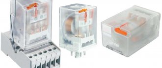
This is a two-contact relay for switching electrical circuits, which is triggered by water pressure in the system. Inside its body there are electrical contacts that are controlled by a membrane.
The pressure switch is most often connected to the pumping station using a special five-piece adapter. In addition to the pressure switch, a pipe from the pump, a pipe from the water supply source, a hydraulic accumulator and a pressure gauge are connected to the adapter.
Read more in the article: How to connect a pump
The pump pumps water into the accumulator. According to the pressure gauge readings, you can observe how the water pressure increases. The pressure switch automatically controls turning the pump on and off.
When the relay is connected to the adapter (connection size - 1/4″), water presses on the membrane, which presses on the springs that control the electrical contacts. The relay contacts are connected in series with the pump motor and supply power to it.
The cable to the relay is connected through special sealed contacts. The operating voltage is 220 V. On the relay itself there are terminals marked “L” (Line), and the electrical cable that comes from the mains is connected to them. The cable from the pump motor is connected to the terminals marked “M” (Motor). The terminal block also has grounding contacts for connecting the grounding conductors of the cables.
When connecting the water pressure switch to the pump, you must remember that the maximum switching current of its contacts is 10A (for some models - 16A).
Relay contact connection diagram
The operating principle of the RM-5 pressure switch is very simple. If the pressure in the system drops below the switch-on level (1.4 bar or a preset value), then the contacts will close and the relay will turn on the pump, and if the pressure in the system is higher than the switch-off level (2.8 bar or also a preset value) , the membrane presses on the springs, the contacts open and the pump automatically turns off. If the pressure drops below the set value, the process is repeated.
Thus, the PM-5 pressure switch is used to automatically maintain water pressure in the water supply system in the operating range of 1.4 - 2.8 bar (factory pressure settings) or 1 - 5 bar (manual settings).
At the factory, these relays are configured according to existing standards and regulations. As a rule, the settings do not need to be changed, because they are the most optimal. Sometimes it becomes necessary to configure the relay to its own operating parameters, different from the factory ones. You can achieve the desired result in adjustment by rotating the two clamping nuts in different directions.
To do this, you need to remove the cover from the relay. There are two nuts in the body - large and small. Using a large nut, you can set the pump shut-off pressure. To increase the response threshold, you need to tighten it clockwise and check the pressure. Using the second nut, you can change the difference between the pump on and off pressure, both up and down.
All these adjustments must be made using a pressure gauge. After adjusting the relay, be sure to close the cover.
Pressure switch RM-5 with built-in pressure gauge
The disadvantages of the RM-5 relay are that it has a rather complicated adjustment of pressure thresholds. In addition, the water pressure in the water supply system is maintained in stages (the relay is activated only at the lower and upper limits). If the water in the well or borehole runs out, it will not be able to turn off the pump. If there is no water, the relay will be turned on until it can create pressure, which can lead to pump failure. Therefore, the RM-5 water pressure switch must be used in conjunction with a fluid flow switch to avoid “dry running” of the pump and its breakdown.
Read also on this topic: AQUAROBOT Turbipress - automatic pump control unit
electric.info
How to make the adjustment correctly
You often come across the position of installers that, they say, the relay pressure set at the factory is enough for the water supply system to work comfortably and satisfy the requirements of the home owner. But, as life shows, having moved to our own private house, where a modern pumping station with a pressure switch is installed, the water pressure does not satisfy us (it is small). Asking a specialist to adjust the pressure in the system is useless (most often), so you should look into this issue yourself.
So, the plumbing system of a house most often consists of:
- The water intake point can be a village water pipe or a well with a submersible pump.
- Pressure switch with hydraulic accumulator.
- Water purification in the form of a system of containers and filters.
- Consumer.
How to properly adjust the pressure switch. Firstly, it is necessary to understand what pressure will be needed so that it is sufficient in the process of opening all points of consumption, especially for the shower, as the most powerful consumer. Secondly, you need to know the pressure at the water intake point. After all, how the relay works, and therefore the pump. If the pressure at the point of intake is below 1.4 atm, the relay will not even turn on, that is, the pump will not work. This often happens if your private house is connected to the village water supply network, where the pressure most often does not rise above 1.0 atm.
If water is drawn from a well or well using a pump, then the pressure in the home network will depend on the technical parameters of the unit. In any case, not lower than 2.0 atm. That is, you don’t have to worry that the relay won’t turn on, so you can safely adjust it.
How to set the lower pressure limit
First of all, it is necessary to adjust the lower pressure level. There are two nuts installed on the relay body. The first (it is larger) regulates exactly the lower level, the second the difference between the lower limit and the upper limit. We are interested in the first one. This nut changes the state of the locking spring. When the nut is rotated clockwise, the spring is compressed, thereby increasing the lower limit of water pressure in the system. When rotating counterclockwise - decrease.
Let's look at an example where there is a need to raise the upper limit, say, to 4.0 atm, and leave the lower limit at the factory limits. To do this, you need to turn the large nut clockwise to the required value. The smaller nut also rotates clockwise until the pump turns on at a pressure of 1.4 atm.
True, this method, as practice shows, is not the most accurate. Moreover, in the factory settings, most often the spring of the small nut is practically weakened, so that it does not create the necessary pressure difference. Its optimal indicator is 1.0 atm, but in fact it is 1.3 atm.
Therefore, it is worth adjusting differently. For example, equalize the pressure using a hydraulic accumulator (these are special expansion tanks for the water supply network, they are blue). True, this method is quite complex and time-consuming. In principle, you have to select the pressure using the “poke” method. That is, we set up the relay, inserted it near the water supply system, and turned on the pump. If the indicators do not match, you need to perform a complete shutdown, drain the water from the expansion tank (from its lower part), and bleed the air from its upper part. And thus adjust the pressure parameters to the required ones. And this can take a lot of time.
Attention! The pressure in the air part of the hydraulic accumulator should be 10-20% less than the lower operating limit of the pumping station. This adjustment can only be made on an expansion tank that is disconnected from the water supply.
There is another option, but to do this you will have to remove the relay housing and make an adapter, because testing and adjustment will have to be carried out not with water, but with air using a compressor. It is the pressure gauge of the compressor unit that will serve as an accurate reference point for the pressure in the device. In this case, you can immediately adjust the relay on the spot with the compressor turned on. It is convenient and fast, and also quite accurate.
Relay connection diagram
And some more useful tips.
- The pressure switch can only be plugged into a grounded outlet.
- The cross-section of the supply electrical cable must correspond to the power of the pumping unit.
- It will be better if another pressure switch with slightly higher pressure thresholds is installed in series in the electrical circuit of the water supply at home. Because the contacts of the RDM 5 device often stick.
Selecting the correct connection diagram for the water pressure switch for the pump
First, it’s worth understanding what the plumbing system consists of:
- its first part is the water intake point. It may be a water pipe or a well;
- hydraulic accumulator;
- pressure switch;
- water purification system. It usually consists of filters and several containers;
- water tap for which comfortable water pressure is provided.
Composition of a modern water supply system
First of all, it is worth understanding what pressure the residents of the house need. It is also important to find out the water pressure at the water intake point. This point is important because at a pressure below 1.4 atm, water is not drawn due to the relay being turned off. Such problems can also arise if you use a city water supply, because the water pressure in it is not always more than 1.0 atm. When drawing water from a well, these difficulties will not arise, and the water supply pressure will depend only on the technical characteristics of the pump.
To ensure uniform and normal water pressure, you should choose the right pumping equipment
It can be seen that each relay has its own setting option; it is usually described in detail in the instructions for a specific device model. All types of relays have a general purpose and mechanism of action.
Model for pumping station
Manufacturer's choice
There are a large number of different models of devices on the market. They differ in price, appearance and have slightly different characteristics.
| Image | Manufacturer and model | Characteristics | Cost, rub. |
| Gilex RDM-5 | Operating temperature from 0° to 40° Pressure range 1.0 – 4.5 atm. Voltage 220 – 230 V, 50 Hz Maximum rated power HP 2 | 900 | |
| Pressure switch PM 1 15, Grundfos | Operating temperature from 0° to 40° The pump starts at a pressure of 1.5 bar and runs as long as there is flow. Dry running protection | 5 655 | |
| Pressure switch PM/5(p)1/4, UNIPUMP | Mains voltage - 230 V, 50 Hz. The maximum switching current is 12A. Working pressure - 5 bar Power - 1500 W. | 467 | |
| Pressure switch PA 5 1-5 bar, WATTS | Pressures from 1 to 5 bar. Pressure drop 0.5 – 2.5 bar. Current 16 A. Maximum coolant temperature 90° In the room 55° | 997 |
Installation and connection
Connecting any mechanism begins with the preparatory stage. First you need to choose the location for installing the relay. According to knowledgeable people, the device should be installed directly near the pump outlet. In this place, turbulence and pressure differences are remarkably leveled out. Before choosing a location, it is imperative to familiarize yourself with the operating conditions of the selected device, because some of them can only be used in heated rooms.
Example of device installation location
The next stage of preparation will be the selection of the necessary pressure thresholds:
- Minimum – determines at what pressure the pump starts operating.
- Maximum – controls the moment the pumps stop working.
- The difference between these two values is called the pressure range. This indicator is directly proportional to the frequency of pump activation.
A device with a special threshold setting scale
The third point of preparation is the registration of parameters. On a household appliance, this process will not cause difficulties, since it is adjusted using a pair of springs, which in turn are regulated by threaded regulators. The relay has two springs:
- a large spring serves to control the upper pressure limit;
- small – determines the pressure difference.
1 – spring for setting the upper limit (pump shutdown);
2 – differential adjustment spring (pressure difference) During preparation, several more devices are installed: shut-off valve, valves (return and breakdown), cleaning filters and sewage drain. Installation should be carried out by professionals or people who at least have an idea of the operating principle and installation rules of such devices. Installation (and then adjustment of the water pressure switch for the pump) must be carried out exactly as written in the instructions:
- First, a tee is installed at the selected location on the pipe, to which a drain valve or fitting connected to the water pressure switch is attached.
- During installation, a threaded connection is used, which should be properly sealed using FUM tape.
- There are devices that cannot be installed in the usual way. They are equipped only with a rigidly fixed nut. During installation, rotate the relay directly.
- Electricity is connected using a cable. Its cross-section must match the requirements of the device, depending on the power.
- The kit sometimes includes a grounding terminal. If available, a grounding cable must be installed.
Appearance of a disassembled relay and electrical connection diagram Example of a mounted and connected device
Should we consider electronic analogues?
Mechanical devices, of course, are more popular, but electronic models have some undeniable advantages:
This device does not require constant adjustment
Prices for electronic water pressure switches for a pump can range from two to four thousand rubles. It depends on the manufacturer, the materials used in production and the store selling it. If you spend some time searching for the right device, you can buy a quality unit at a fair price. If you are purchasing it for long-term use, saving on it is not the best option.
How to configure the pressure switch of a pumping station
Owners of private houses understand that if the relay malfunctions, the entire system may malfunction. The stability of the entire system, and therefore the comfort of all residents of the house, depends on the correct adjustment of the water pressure switch of a household water supply station.
Pressure regulation unit with mini-manometer
Setting up the relay should begin with checking the indicators established at the factory. Typically, the minimum pressure level is 1.5 atm, and the maximum is 2.5 atm. The check is carried out using a pressure gauge. At this point, it is necessary to turn off the pump and ensure that the tank is empty. To measure pressure, a pressure gauge is attached to an empty tank and readings are taken from it.
A pressure gauge will help check the relay performance
Commissioning of the pumping station.
Before commissioning, the pump must be filled with water:
Unscrew the filler plug or open the filler PІРµРЅС‚иль; Fill the pump and suction line with water until it overflows; Tighten the plug (close the filler valve).
For an automatic water supply station, before turning it on, it is necessary to check the compressed air pressure in the accumulator, which should be approximately 1.4-1.5 atmospheres. You can control the pressure level in the accumulator using a conventional tire pump. If the pressure is insufficient, it must be raised to the required level using an air pump.
The following procedure for starting the pump is recommended:
Fill the pump and suction line with water; Close the valve; Plug the pump into a power outlet; Open the valve slightly to allow any remaining air to escape from the pump.
- Let the pump run for 1-3 minutes - during this time water should come out of the pipe at the outlet. If the water does not flow, you need to turn off the pump, add water to the pump and repeat the procedure for starting the pump again.
After starting the pumping station, it is necessary to check the functionality of the automation.
A properly functioning relay should turn off the pump when the system pressure reaches the high relay setting level, and turn on the pump when the pressure drops below the low relay setting level. If necessary, you can adjust the pressure switch to the required pressure to turn the pump on and off within the limits of the pressure developed by the pump.
Pressure switch type PM-5 has a setting range from 1 to 5 bar.
The pressure switch is adjusted in the existing system.
Procedure for adjusting the water pressure switch for the pump
Like any other, this device allows you to supply water to your home water supply with the same pressure. This device is activated after the pressure indicator specified by the setting is reached. At the factory, of course, they set the basic indicators, but most often they are not enough to ensure comfortable pressure, so after the purchase you will have to set your own parameters. Specialists, of course, will do everything efficiently and well, but sometimes it is better to understand an important issue on your own.
Unit ready for installation
Adjusting the pressure switch RDM-5: brief instructions
To correctly adjust the water pressure switch for the pump, you should follow a simple algorithm:
- Fill the tank with water until the required maximum value appears on the pressure gauge.
- Turn off the pumping station for a while.
- Open the housing and gain access to the adjustment springs. You will have to carefully rotate the small nut. At some point the mechanism will work. As you rotate counterclockwise, the pressure level decreases. When rotated clockwise, it increases.
- The lower limit is set by opening the tap and slowly draining the water from the tank.
- When the pressure gauge readings are correct, the process is stopped.
- A large nut is used to adjust the lower parameters. When you rotate it, you will also have to wait for the contacts to respond.
The principle of setting threshold values
This action should be performed once a month, but this is ideal. It is advisable to conduct it at least once per quarter. A small difference between the pressure limits obliges the pumping station to operate with a high frequency of turning on and off the pumps. This operating mode allows you to ensure an uninterrupted supply of water to the tap and at the same time its pressure always remains at approximately the same level, but this will affect the longevity of the pumping station. The large range creates some differences in water pressure, but the pumping station is subject to less stress due to constant switching on and off and, accordingly, will not require repair or replacement for a long time.
Commissioning of the pumping station.
Before commissioning, the pump must be filled with water:
Unscrew the filler plug or open the filler PІРµРЅС‚иль; Fill the pump and suction line with water until it overflows; Tighten the plug (close the filler valve).
For an automatic water supply station, before turning it on, it is necessary to check the compressed air pressure in the accumulator, which should be approximately 1.4-1.5 atmospheres. You can control the pressure level in the accumulator using a conventional tire pump. If the pressure is insufficient, it must be raised to the required level using an air pump.
The following procedure for starting the pump is recommended:
Fill the pump and suction line with water; Close the valve; Plug the pump into a power outlet; Open the valve slightly to allow any remaining air to escape from the pump.
- Let the pump run for 1-3 minutes - during this time water should come out of the pipe at the outlet. If the water does not flow, you need to turn off the pump, add water to the pump and repeat the procedure for starting the pump again.
After starting the pumping station, it is necessary to check the functionality of the automation.
A properly functioning relay should turn off the pump when the system pressure reaches the high relay setting level, and turn on the pump when the pressure drops below the low relay setting level. If necessary, you can adjust the pressure switch to the required pressure to turn the pump on and off within the limits of the pressure developed by the pump.
Pressure switch type PM-5 has a setting range from 1 to 5 bar.
The pressure switch is adjusted in the existing system.
Common faults
The most common cause of breakdowns of pumping stations is a lack of water in the system. The load that appears when there is a lack of water causes the pump to fail in a very short time. In order not to spend money on constantly replacing pumps, you should immediately buy a good relay model and not worry about this cause of failure.
Why is there no fluid in the system?
The main reason for this problem is the large volume of liquid consumption when the volume of the well or reservoir is simply not enough. In the summer, problems often occur that cause interruptions in water delivery. Drought or pipe repairs can cause an unexpected loss of water supply.
The most unpleasant cause is an accident at a pumping station. In this case, you will have to change the pump and all related parts, and at the same time the house will be left without water supply for some period of time.
Corrosion can cause failure of pumping equipment
It is to protect against these unpleasant situations that a water pressure switch for a pump with protection against dry running was invented. This function of the device is capable of opening the contacts and completely turning off the pump. The pump motor will only turn on again when the water flow returns to normal. The indicator, which includes protection against dry running, is set at the factory during manufacture. Most often it is 0.5 atm. This number cannot be changed.
Electrical diagram for connecting the dry running sensor
In addition, manufacturers offer a flow switch that combines its functions with a pressure switch. This version of the device is also capable of ensuring correct operation of the water supply system.
Principle of operation
So, the RDM 5 device is a two-contact relay used for switching the electrical network. It only works depending on the water pressure. Here's how it works:
- The device is adjusted according to the lower and upper limits. If the water pressure in the pumping station of the house is below the upper limit, then the contacts of the relay itself are closed, that is, current flows through its electrical circuit. This means the pump itself is working.
- As soon as the water pressure in the system exceeds the upper limit, the relay is triggered to turn off the supply network, that is, its contacts open.
As you can see, the operating principle of the pressure switch is quite simple. The main thing here is to accurately set the limits.
