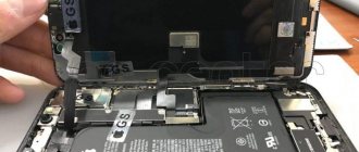
Inexperienced radio amateurs sometimes face the problem of replacing microcircuits on a printed circuit board. When carrying out a seemingly simple process of dismantling radio components, detachment of contact pads or damage to a serviceable element often occurs due to overheating of its housing. This problem arises due to the need to heat a large number of legs at the same time or remove solder from the contacts one by one, which leads to their breakage.
Therefore, for high-quality dismantling, you need to thoroughly study the question of how to desolder microcircuits, as well as which soldering iron to choose for removing radio components from a printed circuit board.
Dismantling needles
Here they threw a set of dismantling needles on Ali. More precisely, tubes. Well, remember this old-fashioned method of desoldering microcircuits? You warm the pad, put a syringe needle on the pad, it separates the pad and the leg, the solder does not stick to it, so it is easily removed. Here is the same thing, only in different diameters and on a comfortable handle. The price is about one hundred rubles, and even with free delivery. Those. freebie finally.
The stings are in a plastic box, very good quality. They don’t hang out, they don’t fly out. The box snaps shut.
- 0.8
- 1.0
- 1.2
- 1.4
- 1.6
- 1.8
- 2.0
- And some kind of 1.2mm awl. Why is it there I don’t understand.
The steel is durable. I soldered a lot of things with them, not a single tube broke.
The thinnest one bent once, pressed hard and it folded 90 degrees. It bent and didn't even crack.
The main drawback of this set is that there is no 0.9mm needle. I have often encountered the problem that a 0.8 needle does not include a component, and a 1.0 needle does not fit into the board hole, and here 0.9 would be ideal. But she is not there, alas. In general, the most popular needles are 0.8, 1.0 and 1.5mm. The rest were rarely useful.
I bought it on Aliexpress, here
. It took about a month.
Well, I made a movie:
Thank you. You are amazing! In just a month, we raised the required amount of 500,000 for a hockey rink for the Aistenok orphanage. Of which 125,000+ were from you, EasyElectronics readers. There were even transfers for 25,000+ and just a flow of payments for 251 rubles. This is incredibly cool. The contract is now being concluded and preparations for construction are underway!
And I was stuck for at least three years of monthly work on articles :)))))))))))) Thank you for such a powerful kick.
Wiring of planar parts
Dismantling using Rose alloy
In this case, the contacts of the microcircuit will close, but this is not scary, after we dismantle the microcircuit, we can easily remove excess solder from the contacts on the board and from the contacts on the microcircuit using the dismantling braid.
So, we took hold of our microcircuit with tweezers, along the edges, where the legs are missing. Typically, the length of the microcircuit, where we hold it with tweezers, allows us to simultaneously move the soldering iron tip between the tips of the tweezers, alternately on both sides of the microcircuit, where the contacts are located, and slightly pull it up with tweezers. Due to the fact that when melting Rose or Wood alloy, which have a very low melting point (about 100 degrees), relative to lead-free solder, and even ordinary POS-61, and moving with the solder on the contacts, it thereby reduces the overall melting temperature of the solder .
Dismantling microcircuits using braid
And thus the microcircuit is dismantled without dangerous overheating. On the board we have the remains of solder, Rose alloy and lead-free, in the form of sticky contacts. To bring the board back to normal, we take the dismantling braid; if the flux is liquid, you can even dip its tip into it, and place it on the solder “snot” that has formed on the board. Then we heat it from above, pressing it with the tip of a soldering iron, and run the braid along the contacts.
Soldering braided radio components
Thus, all the solder from the contacts is absorbed into the braiding, transferred to it, and the contacts on the board are completely cleared of solder. Then the same procedure must be done with all the contacts of the microcircuit, if we are going to solder the microcircuit into another board, or into the same one, for example, after flashing it using a programmer, if it is a Flash memory chip containing the BIOS firmware of a motherboard, or monitor, or what or other technology. This procedure must be performed to clean the microcircuit contacts from excess solder. After this, we apply the flux again, place the microcircuit on the board, position it so that the contacts on the board strictly correspond to the contacts of the microcircuit, and there is still some space left on the contacts on the board, along the edges of the legs. For what purpose are we leaving this place? So that you can lightly touch the contacts with a soldering iron tip and solder them to the board. Then we take a 25-watt EPSN soldering iron, or a similar low-power one, and touch the two legs of the microcircuit located diagonally.
Soldering SMD radio components with a soldering iron
As a result, the microcircuit turns out to be “stuck” and will not budge, since the melted solder on the contact pads will hold the microcircuit. Then we take solder with a diameter of 0.5 mm, with flux inside, bring it to each contact of the microcircuit, and simultaneously touch the tip of the soldering iron tip, the solder, and each contact of the microcircuit. I do not recommend using solder of a larger diameter; there is a risk of adding “snot”. Thus, we have solder “deposited” on each contact. We repeat this procedure with all contacts, and the microcircuit is soldered into place. If you have experience, all these procedures can actually be completed in 15-20 minutes, or even in less time. All we have to do is wash off the remaining flux from the board with solvent 646, or Flux Off cleaning agent, and the board is ready for tests after drying, and this happens very quickly, since the substances used for rinsing are very volatile. 646 solvent, in particular, is based on acetone. Inscriptions, silk-screen printing on the board, and solder mask are not washed off or dissolved.
The only thing is that dismantling a microcircuit in a Soic-16 or more multi-pin package in this way will be problematic due to difficulties with simultaneous heating and a large number of legs. Happy soldering everyone, and fewer overheated microcircuits! Especially for Radio circuits - AKV.
Discuss the article SOLDERING SMD PARTS WITHOUT A HAIR DRYER
Soldering the microcircuits
Soldering the IC with a needle
Everyone solves this problem in their own way based on their experience and capabilities. But even having the opportunity to use a soldering station with a hair dryer, some still use this method. Me too. Therefore, in this article I decided to write how to desolder a microcircuit from a board using a needle from a syringe that I still use.
You can desolder the IC in several ways:
- using suction;
- soldering iron with nozzles;
- soldering iron using tubes;
- hair dryer (more suitable for desoldering large surface-mount ICs with planar leads).
Some will say that this is the last century and it’s time to switch to more modern methods, but I like it because it allows you to desolder the microcircuit with a soldering iron, quickly and accurately. Whether this is right or wrong is up to you to decide for yourself. Of course, it is not suitable for all cases, for example, in order to desolder an SMD chip, you need a different technology.
Syringe needle
You don’t need to dream of any new devices or expensive soldering irons to solder radio components; this is the cheapest and most practical way that allows you to solder a microcircuit with a regular soldering iron at home using an ordinary needle from a syringe, which, if not lying around in the medicine cabinet, is easy available.
There are several advantages here:
- the microcircuit does not overheat;
- the paths do not deteriorate;
- neighboring radio components do not heat up;
- accessibility and simplicity;
- cheapness.
Desoldering pump for desoldering radio components
The destin pump is used like this: cock the spring, bring the tip to the contact heated by the soldering iron and press the spring release button, due to the created vacuum, the molten solder is drawn into the destin pump. I use the one in the photo, if the desoldering pump stops drawing in solder, you need to disassemble and clean the rubber ring on the piston. These methods (braiding and desoldering) have advantages over heating the soldering area with a soldering hair dryer in that, for example, when desoldering plastic connectors for further use, there is no risk that they will melt. Also, a syringe needle is suitable for eliminating short circuits between “stuck together” adjacent legs of microcircuits. In this case, we warm up the soldering area with a soldering iron and pass the needle between the legs of the microcircuit in order to separate them so that there is no contact between them. Review prepared by AKV
.
Soldering microcircuits from the board is a non-trivial task, regardless of the type of controller. You unsolder one leg, but while you are working on the other, it freezes. You can bend the legs after unsoldering, but the problem of contacts breaking off again arises. The question arises, how to desolder a microcircuit from a board with a soldering iron? The answer is quite simple: use knowledge of physics and available objects. There are a number of options for carefully removing microchips from the board. But first, a little theory.
How to desolder radio components from a board with your own hands - we explain in order
When some equipment breaks down, it is not at all necessary to immediately throw it in the trash. If you are interested in electronics and radio engineering, it would be wiser to solder the working elements of the microcircuit. Suddenly, in the future you will need a capacitor, transistor or resistor if you decide to make a homemade electronic product. In this article we will tell you how to desolder radio components from the board so as not to damage anything.
What do you need for this?
There are many devices for soldering parts. Of course, a radio amateur cannot do without a soldering iron, which will be the main assistant in this matter. However, in addition to the soldering iron, in order to desolder the element, you will need:
- Tweezers. To remove heated radio components. Instead of tweezers, you can use an alligator clip (shown in the photo below). The advantage of the clamp is that it will securely grip the part and also become a good heat sink.
- Hollow needles for dismantling. Buying them will not be a problem, the cost is low. Using needles, you can desolder a radio component quickly and accurately, which we will discuss below.
- Dismantling braid. It serves as a so-called sponge that absorbs molten solder into itself, thereby cleaning the board.
- Destination pump. The name speaks for itself. An indispensable item for frequent desoldering of radio components from boards at home.
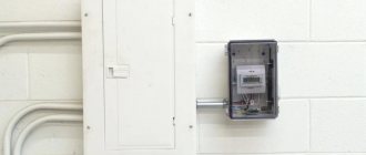
You also need to prepare your workplace. It should be with good lighting. It is best if the lamp is located above the workplace so that the light falls vertically without creating shadows.
Assembly order
Direct assembly of the soldering device is carried out in the following sequence.
First, a nichrome spiral with a cross-section of about 0.4-0.5 millimeters is wound onto a tubular frame with a diameter of 5-6 millimeters. The total length of the wire segment is selected based on the required electrical resistance (at least 70-90 Ohms).
As a tubular base, you can take the corresponding part from a store-bought product (soldering iron) type EPSN-100.
When winding an element, individual turns of the spiral should be laid with equal spacing, so that they do not touch each other. After this, the finished spiral heater is tightly wrapped with a piece of fiberglass of the required size, and on top is wrapped with an asbestos gasket.
The latter is fixed to the fiberglass using heat-resistant glue, after which a heat-insulating tube pre-measured in size is put on it (porcelain, ceramics or quartz glass can be used for this).
Upon completion of the assembly of this unit, the ends of the wound and protected spiral are brought out.
Then the finished heating element is inserted into the outlet channel of the body of the old hair dryer, which is pre-insulated with any heat-resistant material at hand (mica, asbestos or quartz).
Chip types
Currently, there are a number of cases, but only two are the most widespread, and in fact all other varieties are variants of two main types:
- DIP - roughly speaking, this version of the case is for internal mounting; the legs of this controller are placed in holes on the board;
- SMD – this type of microchip is designed for surface mounting; in this case, “spots” are placed on the board, to which the legs of the microcircuit are soldered.
Each option has its own advantages and disadvantages. But within the framework of the article, their features in terms of wiring are interesting. We’ll look at how to unsolder a microcircuit in a particular case a little lower.
Related materials
The main tool is a soldering iron!... A soldering iron. How to choose it and how to deal with it later. Our city is home to not only seasoned...
Creating acoustic systems at home. CM. Afonin... Creating acoustic systems at home. CM. Afonin Publisher: Eksmo Year of publication: 2008…
Unexpected case mod of the Lukey 868 soldering station. Report about one curious alteration... It all started trivially. I, like many other users, have problems with this...
Metallization of via holes of a printed circuit board with cable lugs... I remember in childhood, when foil getinax was made independently, using BF glue and...
Kruse Density Toner and the path to perfection of photoresist technology... It is unlikely that any radio amateur would not like to make high-quality, accurate printed...
Assembling and programming mobile robots at home. Zhimarshi F…. Assembling and programming mobile robots at home. Frederic Zhimarchi. Publisher: NT...
Removable hair dryer in the Lukey 702 soldering station... I solder for myself, from time to time. Gradually the details became smaller and smaller, standard...
A method for installing a lamp structure for convenient setup... The article describes the design of a module for small lamp structures that imitates a printed circuit...
Restoring tube panels... Radio amateurs who decide to assemble a tube amplifier often face the problem of obtaining...
Soldering station LUKEY 702. We eliminate some shortcomings... Well, where would we be without the Chinese “snot” - the favorite and universal all-Chinese fixative! So in my...
Program "Handbook of SMD" v.3.1... SMD elements are widely used in modern electronics, and even in amateur radio designs...
Homemade products of a young radio amateur. B.S. Ivanov... Boris Sergeevich Ivanov Homemade products of a young radio amateur. - M.: DOSAAF, 1988. - 140 p., ill. Described...
Necessary tool
Soldering iron
Old models
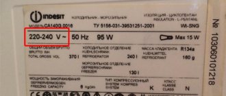
A properly selected soldering iron can ensure normal heating of the contact tracks of boards and semiconductor leads.
The old EPSI model of the “Moment” type with a power of 65 watts has a universal design. It is not difficult to make it with your own hands.
Previously, resistive type models with a heating element made of thin nichrome wire were widely used.
Modern soldering irons
For specific soldering conditions, you can now purchase various types of models equipped with all sorts of functions.
For example, a soldering iron with tin suction has been specially designed for soldering microcircuits, transistors and diodes.
It quickly heats up a layer of solidified solder and easily removes it in a liquid state from the contact pad.
Radio component holders
When heating the transistor leg for tinning and soldering, you should always remove the heat from the body and semiconductor layer with some metal object.
For this purpose, tweezers or alligator clips are usually used. However, it is most convenient to work with a medical instrument with thin legs, which surgeons use during operations.
Fixing electronic boards
Radio components and boards are usually small in size and require reliable fixation in space. Soldering them while hanging is dangerous: a small wrong movement can damage the entire structure.
Additional training
For additional training, you can try soldering various unnecessary boards from computers and smartphones. There are many SMD and DIP components on motherboards. Only long and hard hours of practice will help you develop your soldering skills.
Net
As an exercise, you can try soldering a grid of wires. The quality of soldering is assessed by the load on this soldered wire mesh. If the solder joints do not break under load, then the soldering is excellent.
Constructors
Radio designers are also a great help.
They teach you to understand electrical circuits and the intricacies of soldering. You should start with simple constructors, such as flashing lights or door locks. As your skill increases, you can increase the level of difficulty, reaching complex LED cubes.
Soldering with acid
Acid is used only as a last resort, when a heavily oxidized surface cannot be tinning. All parts, wires and connectors can be soldered perfectly without acid. Read more about soldering acid
Removing the DIP package
As already noted, this type of microcircuit is distinguished by its installation in holes on the circuit board. This imposes certain restrictions on the process of its dismantling. In order to carefully remove its legs from the holes, you need to remove the solder from the joint, almost completely freeing the legs. It should be noted that alternate heating and dismantling of a separate contact will not work here, since when it cools down, the remaining solder will again fix the microchip in place. Therefore, wiring DIP package is optimal using the following methods:
- Using improvised means - needles from medical syringes or special hollow tubes, now sold in electrical stores, are suitable for this purpose. But the option of using a medical needle is the cheapest and most accessible. To do this, you need to select a needle with a diameter slightly smaller than the mounting sockets for the microchip leg. Then cut off its pointed part with a file or simply bite it off, and then grind off the flattened part with a file. After this, installing the resulting hollow tube with an even cut on the mounting socket, simply heat it with a soldering iron, thereby freeing the chip leg;
- The second option is to drag the solder from the soldering site onto copper wires moistened with flux, such as alcohol rosin. A wire with flux heated by a soldering iron gradually draws the solder onto itself from the soldering site. This option takes longer, but is also quite effective;
- Using a soldering iron with solder suction - in this case, no particular difficulties in dismantling are expected. The main thing is to control the heating temperature in the contact area so as not to damage the board and the part itself.
These options will allow you to quickly and efficiently desolder DIP packages from the board.
Important! The main requirements for using a soldering iron in this case will be constant control over the pressure and temperature in the soldering zone. Overheating and excessive pressure can damage the part.
Important! When using a medical syringe needle, you can simplify the task of cutting it; to do this, before cutting, it is enough to red-hot the cut area.
Example of soldering for a soldering iron with a copper tip
Any soldering begins with tinning pads, wires, and other elements that will need to be connected together. Tinning is actually a surface coating of surfaces with solder. The purpose of this procedure is simple. The surface layer will provide good cohesion for future welding solder, and therefore a reliable connection during soldering. Here it is necessary to say something about the materials that you are going to solder. So let’s say, it will be good to solder, ferrous metals are already worse, but I wouldn’t advise you to solder aluminum at all. Because this is a troublesome and thankless task. It is here that it is necessary to say that if you have a choice, then choose copper wires and connectors for soldering; this choice will allow you to solder comfortably. So, about tinning with a copper soldering iron. We heat up the soldering iron, usually this time is 5-7 minutes. Don't even try before. During heating, you can dip the soldering iron into rosin or solder fat once to prevent oxidation of copper.
As soon as the tip begins to confidently melt the solder, consider it warmed up.
During this time, you can still clean the wire or pad from insulation and oxide. If it is a stranded wire, then after removing the insulation, twist all the wires together. Also, if the connection is permanent, then also connect the wires of different conductors to each other. Now place the wire(s) on the platform and treat it with acid, rosin, or fat.
That is, with the reagents that I wrote to you about earlier. They are the ones who will contribute to tinning, and as a result, to the soldering itself. In our case, this is solder fat, I heated it and dipped the wire in it. Now we grab an excess portion of solder onto the tip, in fact it will be a drop of solder. We bring it to the conductor and move along it.
The conductor should be filled evenly.
Now it will look like something covered in a metal shell. If there is not enough solder, then again take the solder with a tip and distribute it at the soldering site.
We carry out the same procedure with the other conductor. Now you can solder the conductors together. We set them up the way we need them and each time, bringing a little solder on the tip of the pin, we fill the gap between the conductors.
If necessary, take solder and bring it to the soldering site.
The result is a beautiful, durable and reliable contact. If necessary, the conductors can be twisted before soldering.
We isolate the soldering area. Now about soldering to the board. Here again we need to start with tinning the board tracks. If you are mounting something on a universal circuit board, then immediately take a board with tinned contacts. Next, we straighten the contacts of the radio component and insert them into the holes so that they protrude from the other side by 0.5-1 mm. Now, as in the case of the wire, we take solder onto the tip and bring it to the leg-hole location.
We touch it, and the solder spreads along the leg, filling the hole. So we solder all the legs of the radio element (wires).
Now, although you haven’t learned how to solder with a soldering iron with a copper tip, you know how it’s done.
Maintenance (tinning) of a copper soldering iron tip during and after soldering
As I already told you, the copper tip fades over time and eventually changes its shape. As a result, it is necessary to put its shape in order from time to time. It is best to forge the tip, that is, use a hammer and anvil, and tap out the desired shapes. But if this is not the case, then you can get by with a simple needle file.
We take and process the sting so that it fits the shape (size) that is convenient for you. For me, this shape is the shape for a flat-head screwdriver. The two sides are ground off with a needle file, resulting in a smooth but “bare” metal – copper.
It must be said that copper is a soft metal. Handles it accordingly easily. After this shaping, it is necessary to protect the tip from oxidation. This is done simply by applying solder to the surface layer of the tip, which performs two functions. Firstly, we use it to solder, which we have already discussed. Secondly, it protects the tip from oxidation and burnout. So, when we processed the tip cold, we turn on the soldering iron. While it is warming up, but not yet warmed up, you can dip the tip in rosin or solder fat.
Then we take solder and apply it to the heated tip. The solder itself will spread over its surface. The entire tip is ready for use.
Restoration of the tip must be carried out periodically when you notice that the area on it has become uneven, and as a result, soldering has become inconvenient.
SMD controllers
Surface mounting of the housing makes it easier to dismantle. In this case, you can use a wide soldering iron tip and copper wire with flux and solder several contacts at once. But there are more interesting desoldering methods:
- Using a strip of metal or half a razor blade to distribute the heat of a soldering iron over one row of IC legs. In this case, a steel strip is installed on a row of contacts on one side and heated with a tip until the solder melts, after which this side is slightly raised above the board. Then the solder on the other side of the chip is melted in the same way;
- Using a long piece of copper braid with flux applied to it. The segment is placed on the legs of the microcircuit on one side and heated with a soldering iron; pulling the solder onto the braid, lift the part with tweezers. Then remove the solder from the other side of the controller in the same way;
- A technically interesting option is to use Rose or Wood alloys. Drops of this solder are applied to the contacts and heated, thereby reducing the melting point of the solder. Next, the solder gradually warms up, and the microcircuit is dismantled;
- Using a hair dryer or blowtorch. To use this tool, flux is applied to the soldering areas. After that, the surface and the part are heated, and the microcircuit is removed from the mounting spots with tweezers.
It should be noted that each dismantling option is used in specific conditions; the main task in this case is to select the most optimal option from a safety point of view and, when using it, not to damage the part itself or the board traces.
Important! When dismantling the microcircuit, it is important to remember that any parts or components on the board have their own temperature minimum; exceeding it will lead to the failure of the microcircuit.
Using improvised means and a soldering iron when installing or dismantling microcontrollers is quite justified, but requires at least skills in working with a soldering iron. If they are absent, you should first practice on unnecessary parts. This process will allow you to gain the necessary experience on how to unsolder a microchip without damage, and also choose the most optimal option for working with a specific board and type of chip case.
Desiccant pump: how to use it correctly
A vacuum desoldering pump is a very useful tool for soldering various radio components, be it microcircuits, a transistor, or, for example, a diode. Also, high-quality removal of tin from the contacts will help solder the working part without much difficulty.
The desoldering pump consists of:
- Vacuum flask, spout made of thermal material;
- Return spring;
- Piston.
Soldering radio components with a desoldering pump is quite simple. First of all, it is necessary to “cock” the destin pump. To do this, you need to fix it with a locking mechanism by pressing the piston (the fixation occurs automatically). Next, with a soldering iron heated to the optimal temperature, we melt the tin on the contact of the part, having previously attached a destin pump to the contact.
After the tin has melted, remove the soldering iron, press the tin pump to the desoldering area and press it tightly. Press the locking mechanism button. The piston, moving back through the flask, creates a vacuum, due to which the tin is sucked in.
If you don’t have a desoldering pump at hand, and the part needs to be unsoldered, then you can make one from a regular syringe with your own hands. To do this, you need to take a syringe (50 cc if possible). We take out the piston and place a return spring in the syringe flask (the spring should be no longer than the flask so as not to squeeze out the piston). All that remains is to protect the nose. This can be done with any metal tube of the appropriate diameter. And the homemade desoldering pump is ready for use.