Star and delta are the main types of connections in three-phase current installations. Each scheme has properties unique to it, and it is important to apply or combine it correctly.
This review is aimed primarily at a wide audience who may not know the terminology, calculation features, vectors and other highly specialized information. And there is no point in it if there is no understanding. And retransmission of textbooks and other electrical literature without proper explanation is a road to nowhere. Therefore, we will try, in as simple terms as possible, to consider the main features of using star and triangle schemes.
Where is the star-delta connection used?
If we analyze the search results, it turns out that most often people are looking for information about star and delta circuits in the context of connecting an asynchronous three-phase motor. Naturally, at the everyday level, this is the most common case of using one or another scheme. And, naturally, we will consider the features of using this or that circuit when connecting a three-phase consumer. But first I would like to highlight the equally important use of star and delta combinations in the distribution of electricity from a power plant through transformers to consumers.
It would seem, why do we need to know the features of electricity transformation? However, the topic is quite interesting, complex and poorly covered. After all, we all know that electricity is generated at a power station by generators, transformed and supplied to our homes. And if with the last link everything is more or less clear. The information about the first two links is often vague, sometimes contradictory or difficult to understand. Therefore, let's consider a simple explanation of the transformation of electricity through star-delta, triangle-star combinations. But first we give definitions of these connection methods.
Star, triangle - definitions
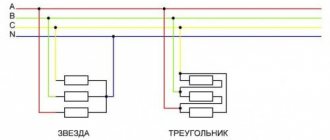
Depending on the method of connecting the generator windings and the load, a distinction is made between star and delta connections. Each phase winding of the generator has two terminals, which are conventionally called the beginning and the end. The beginning of the winding is taken to be the terminal to which the positive EMF is directed.
When connected by a star, the ends of all phases of the generator are connected into one node. It is called the neutral node or neutral point. The neutral points of the generator and the load are often connected with a neutral (neutral) wire. The remaining wires connecting the generator windings to the receiver are called linear.
In a delta connection, the beginning of one phase winding is connected to the end of the next so that the three windings form a closed triangle.
In practice, various combinations of generator and load phase connections are used: star-star, star-delta, delta-delta. There are also combinations with a zigzag, but we will not touch on them in this review.
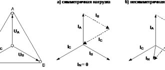
Voltages and currents in the generator and load phases are called phase and are designated Uph, Ia. The voltages between linear wires and the currents in them are called linear and are designated Ul, Il. From the diagrams discussed above it follows that when connected by a star, Il = Iph, and when connected by a triangle, Ul = Uph.
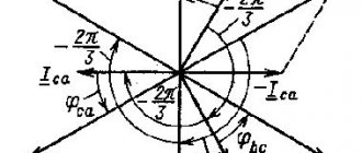
If the windings of a 220 Volt power source are connected in a triangle, the phase and line voltages are respectively equal to 220 Volts. The relationships between linear and phase voltages when connected by a star are already different. You can find them using a vector diagram or by analyzing sinusoids of three phases, as shown in the following video:
Calculation of linear voltage by vectors comes down to the analysis of an isosceles triangle with base angles of 30°. You can also calculate the difference between vectors using complex numbers. We will not dwell on these methods in detail. Let us only note the consequence - when connected by a star, the linear voltage Uл = √3 × Uф (380 = √3 × 220).
Ramp voltage generator
The triangular voltage generator, made according to the previous circuit, is easily converted into a sawtooth voltage generator. To do this, it is enough to provide different durations for charging and discharging the capacitor in the integrator circuit. Such changes are shown in the figure below
Sawtooth oscillation generator.
As it is easy to notice, the changes made concern the charge-discharge circuit of capacitor C1 in the integrator. Diodes VD1 and VD2 allow you to charge and discharge the capacitor with different currents. With the polarity of the diodes shown in the diagram, the duration of the discharge of capacitor C1, and therefore the duration of the linearly increasing voltage, is determined by the resistance value of the resistor R4', and the duration of the charge C1 and the linearly decreasing signal at the output of the integrator is determined by the resistance R4” according to the following formulas
All other aspects of the circuit's operation are similar to the previous one. Since the circuit is not symmetrical, resistor R5 can be removed. The frequency of the output ramp voltage will be determined by the sum of resistors R4' and R4”. Frequency stability in this circuit will be limited by the temperature instability of diodes VD1 and VD2
Theory is good, but you need to practice it all practically. YOU CAN TRY HERE
Voltage transformation using star and delta combinations
With a power plant generator power of 500 MW and a voltage of 10 kV, the current in the wires will be 50 thousand amperes. When transmitting over long distances, wires, as a load, have significant resistance. Consequently, most of the current will be wasted heating the wires. To minimize losses during the transportation of electricity, the only effective way is to increase the voltage, which will lead to a decrease in current. But without distribution transformers (step-up and step-down) this cannot be done.
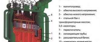
Now we will not dwell in detail on the principle of operation of the transformer. We are more interested in the peculiarity of connecting its windings with a star or triangle.
We will simulate in the Multisim program. Let's start drawing the circuit with a three-phase generator, the windings of which are connected in a star. We ground the connection point of the windings. At this stage, we note that despite the fact that generators at power plants generate voltages of thousands of volts and transform it all the way by increasing and decreasing, we will take a generator that generates 220 volts that we understand. Also, you should not compare the diagrams shown here with a real system, since the path from the power plant to the consumer is much more complicated.
Now let's add a transformer. More precisely, we will assemble it from three transformers in such a way that the primary winding is connected in a star, and the secondary in a triangle. We will not increase the voltage, but let’s see what transformation occurred when connecting the transformer windings according to the star-delta circuit.
When switching from star to delta windings of generators or secondary windings of transformers, the following occurs:
- The network voltage decreases by 1.73 times. In our case, the line voltage is reduced from 380 to 220 Volts.
- The power of the generator and transformer remains the same. And all because the voltage of each phase winding remains the same and the current in each phase winding is the same, although the current in the linear wires increases by 1.73 times. We will show this a little later, when we close the circuit through consumers. But first, let’s add another transformer with a delta-star circuit to our circuit and connect the load to it.
When switching generator windings or secondary windings of transformers from delta to star, the opposite phenomena occur:
- The line voltage in the network increases by 1.73 times. In our case, from 220 to 380 Volts.
- The currents in the phase windings remain the same, the currents in the linear wires decrease by 1.73 times.
Now let's understand the reasons for transformations in simple words without using vectors. To do this, consider the movement of free electrons in a circuit and analyze the potentials at a specific moment in time. You probably won’t see this explanation anywhere, but it is perhaps the easiest to understand.
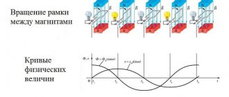
The first thing in our chain is the generator. Simply put, it has three stator windings offset by 120° relative to each other. When the rotor rotates, a periodically varying EMF with an amplitude of approximately 312 Volts appears in the stator windings. This is the amplitude value of the voltage, and we will not move from it to the actual voltage. At the moment when the voltage at one of the generator terminals is +312 Volts, at the other two -156 Volts. Let's stop at this point and move on to the voltages of the transformer windings.
The voltages at the considered moment in time both on the primary winding and on the secondary winding correspond to the +312, -156, -156 Volts highlighted above. So why do the currents in the linear wires extending from the triangle windings increase by the root of three times, and the linear voltage decreases by the same amount? The whole secret is in particular the connection of the windings in a triangle, and then we will clearly demonstrate this by moving to a more simplified diagram.
Since in a delta connection the beginning of one phase winding is connected to the end of the next, the winding voltage of +312 Volts will be distributed between the winding with a voltage of -156 Volts and the output. As a result, the output of the winding with a voltage of +312 Volts will be +156 Volts, and the output of the winding with a voltage of -156 Volts will be 0 Volts. We are left with the third winding with a voltage of -156 Volts, and at its output it will remain -156 Volts. As a result, we get the output voltage at the moment we considered +156, -156, 0 Volts (and it was +312, -156, -156 Volts).
The resulting linear voltage is +156-(-156) = +312 Volts (this is the amplitude value). After converting to the actual value, we get 220 Volts. Why is 0 Volt not considered? You need to understand that the frequency of 50 Hertz has not disappeared anywhere, and where there is zero, in a moment it will be +156, in another moment -156. And such alternation will be constant. But let's return to the moment in time in question. We sorted out the drop in line voltage from 380 to 220 Volts. Now let's explain why the current increased. It's actually simple. Having reduced the voltage to transmit the initial power, we need to proportionally increase the current.
When moving from a triangle to a star, a reverse transformation occurs. To see this in the diagram, you need to find the winding voltages on the second transformer connected in a delta-star circuit. Having calculated the potential differences between the beginnings and ends of the windings, we will return to the original +312, -156, -156 Volts.
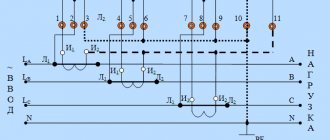
In order to confirm our calculations and clearly see the phase shift, let’s return to the Multisim program and connect an oscilloscope to the phases.
A phase coming from a generator with star windings is connected to pin A of the xsc1 oscilloscope. The remaining three pins of this oscilloscope are connected to the phases after the star-delta transformation. As you can see, after the transformation of the sinusoid, the phase shifted by 30°. And if you move the cursor to the amplitude value ≈ +310 Volts of channel A, then on the remaining channels related to the phases after transformation there will be approximately +155, -155 and 0 Volts. That is, the oscilloscope showed the same thing that we calculated earlier.
To analyze the reverse transformation, we connected the same phase from the generator to pin A of the xsc2 oscilloscope, and the remaining pins were connected to the phases after the delta-star transformer. As a result, the shift disappeared and the phase sinusoids returned to their amplitudes of 312 Volts. True, if you pay attention, the sinusoids of the phases after the transformation were mirrored in relation to the sinusoids of the phases after the generator. In order to reflect back, it is enough to swap the terminals of the windings according to the star circuit.
As you can see, by using various combinations of “star” and “triangle” with the same inductances of the primary and secondary windings, you can move from one voltage to another. And in order to see all this clearly, it is enough to use a program for modeling digital and analog electronic circuits. In our case, the simulation was carried out in the Multisim program environment.
Basic circuit for generating ramp voltage
To understand how the formation of a linearly increasing voltage occurs, let us recall how the transient process occurs in integrating RC circuits. To do this, let us depict a circuit for charging a capacitor with a certain current I
Capacitor charge graph.
Capacitor Q is charged by direct current I in time t
At the same time, the voltage UС on a capacitor with capacitance C is determined by the amount of charge Q accumulated in the capacitor
Thus, the voltage UC on a capacitor with capacitance C, which is charged by current I, will be determined by time t
Since the value of capacitance and current are constant, the voltage to which the capacitor is charged is proportional to the time that has passed since the switch is closed. Thus, the voltage on the capacitor UC is actually the sum of the voltages over the entire period t. Such summation is called integration , and the circuit that performs such an operation is called an integrator .
I discussed the op-amp integrator in one of the previous articles and is shown in the figure below
Operational amplifier integrator circuit.
In this circuit, the charging current I of capacitor C1 is determined by the input voltage UBX and resistor R1, then the output voltage will be calculated by the following formula
The “–” sign in the expression indicates that the input signal is supplied to the inverting input of the op-amp.
The integrator described here, which has a linearly varying voltage form at the output, is the basis for constructing triangular and sawtooth voltage generators.