Greetings, friends!
In the first part of the article, we looked at how an electromagnetic relay works.
And they saw that it contained a winding with a metal core, a movable armature and contacts.
We understood why it was needed.
Now we will take a closer look at the relay and look at
Operating principle
Essentially, a relay is an electromagnet. When control voltage is applied to the coil, the rod attracts the armature, thus switching the circuit.
There are three types of relays:
- with normally closed contacts;
- with normally open;
- throwing over.
When a control signal is applied to a device with normally closed connectors, they open; if there is no signal, they close. For relays with open connectors, the opposite is true. There is voltage on the winding, the terminals close, but when there is no voltage, it opens. In flip-over models there are two sets of connectors, one normally closed and the other normally open. They have a common terminal. When current is applied to the winding, the contacts switch from one position to another.
Automotive relays: how they are designed, how to select and check them
Cars are becoming smarter from year to year - they already independently rotate the steering wheel, change the stiffness of the suspension, massage the driver’s butt and much more... However, the final actuator of most electrical circuits of a car, a modest “workhorse”, is a relay that has practically not changed its design all the way back to 1831, when it was first invented... What is useful for an ordinary car owner to know about relays?
How a relay works and is used
As is known, the dimensions and power of a switch switching a powerful load must correspond to this load. You cannot turn on such serious current consumers in a car as, say, a radiator fan or glass heating with a tiny button - its contacts will simply burn out after one or two presses. Accordingly, the button should be large, powerful, tight, with a clear fixation of the on/off positions. It must be connected to long thick wires designed to carry the full load current.
But in a modern car with its elegant interior design there is no place for such buttons, and they try to use thick wires with expensive copper sparingly. Therefore, a relay is most often used as a remote power switch - it is installed next to the load or in a relay box, and we control it using a tiny, low-power button with thin wires connected to it, the design of which can easily fit into the interior of a modern car.
Inside the simplest typical relay there is an electromagnet, to which a weak control signal is supplied, and a movable rocker arm, which attracts the triggered electromagnet, in turn closes two power contacts, which turn on a powerful electrical circuit.
In cars, two types of relays are most often used: with a pair of normally open contacts and with three switching contacts. In the latter, when the relay is triggered, one contact closes to the common one, and the second one is disconnected from it at this time. There are, of course, more complex relays, with several groups of contacts in one housing - making, breaking, switching. But they are much less common.
Please note that in the picture below, for a relay with a switching contact triple, the working contacts are numbered. The pair of contacts 1 and 2 are called "normally closed". Pair 2 and 3 are “normally open”. The “normal” state is considered to be the state when voltage is NOT applied to the relay coil.
The most common universal automotive relays and their contact terminals with a standard arrangement of legs for installation in a fuse box or in a remote socket look like this:
The sealed relay from the aftermarket xenon kit looks different. The compound-filled housing allows it to operate reliably when installed near headlights, where water and mud mist penetrate under the hood through the radiator grille. The pinout is non-standard, so the relay is equipped with its own connector.
To switch large currents, tens and hundreds of amperes, relays of a different design than those described above are used. Technically, the essence is unchanged - the winding magnetizes a movable core to itself, which closes the contacts, but the contacts have a significant area, the fastening of the wires is for a bolt from M6 and thicker, the winding is of increased power. Structurally, these relays are similar to the starter solenoid relay. They are used on trucks as ground switches and starting relays for the same starter, on various special equipment to switch on particularly powerful consumers. Occasionally, they are used for emergency switching of Jeeper winches, creating air suspension systems, as the main relay for homemade electric vehicle systems, etc.
By the way, the word “relay” itself is translated from French as “harnessing horses,” and this term appeared in the era of the development of the first telegraph communication lines. The low power of galvanic batteries of that time did not allow transmitting dots and dashes over long distances - all the electricity “went out” on long wires, and the remaining current that reached the correspondent was unable to move the head of the printing machine. As a result, communication lines began to be made “with transfer stations” - at an intermediate point, the weakened current activated not a printing machine, but a weak relay, which, in turn, opened the way for current from a fresh battery - and on and on...
What do you need to know about relay operation?
The voltage indicated on the relay body is the average optimal voltage. Car relays are printed with “12V”, but they also operate at a voltage of 10 volts, and will also operate at 7-8 volts. Similarly, 14.5-14.8 volts, to which the voltage in the on-board network rises when the engine is running, does not harm them. So 12 volts is a nominal value. Although a relay from a 24-volt truck in a 12-volt network will not work - the difference is too great...
The second main parameter of the relay after the operating voltage of the winding is the maximum current that the contact group can pass through without overheating and burning. It is usually indicated on the case - in amperes. In principle, the contacts of all automotive relays are quite powerful; there are no “weaklings” here. Even the smallest switches 15-20 amperes, standard size relays – 20-40 amperes. If the current is indicated double (for example, 30/40 A), then this means short-term and long-term modes. Actually, the current reserve never interferes - but this mainly applies to some kind of non-standard electrical equipment of the car that is connected independently.
Automotive relay terminals are marked in accordance with the international electrical standard for the automotive industry. The two terminals of the winding are numbered “85” and “86”. The terminals of the contact “two” or “three” (closing or switching) are designated as “30”, “87” and “87a”.
However, the marking, alas, does not provide a guarantee. Russian manufacturers sometimes mark a normally closed contact as “88”, and foreign ones – as “87a”. Unexpected variations of standard numbering are found both among nameless “brands” and among companies like Bosch. And sometimes the contacts are even marked with numbers from 1 to 5. So if the contact type is not marked on the case, which often happens, it is best to check the pinout of the unknown relay using a tester and a 12-volt power source - more on this below.
The relay contact terminals to which the electrical wiring is connected can be of a “knife” type (for installing the relay into the connector of the block), as well as a screw terminal (usually for particularly powerful relays or relays of obsolete types). The contacts are either “white” or “yellow”. Yellow and red - brass and copper, matte white - tinned copper or brass, shiny white - nickel-plated steel. Tinned brass and copper do not oxidize, but bare brass and copper are better, although they tend to darken, making contact worse. Nickel-plated steel also does not oxidize, but its resistance is rather high. It’s not bad when the power terminals are copper, and the winding terminals are nickel-plated steel.
In order for the relay to operate, a supply voltage is applied to its winding. Its polarity is indifferent to the relay. Plus on “85” and minus on “86”, or vice versa - it doesn’t matter. One contact of the relay winding, as a rule, is permanently connected to plus or minus, and the second receives control voltage from a button or some electronic module.
In previous years, a permanent connection of the relay to the minus and a positive control signal was more often used; now the reverse option is more common. Although this is not a dogma - it happens in every way, including within the same car. The only exception to the rule is a relay in which a diode is connected parallel to the winding - here polarity is important.
If the voltage to the relay winding is supplied not by a button, but by an electronic module (standard or non-standard - for example, security equipment), then when turned off the winding gives an inductive voltage surge that can damage the control electronics. To suppress the surge, a protective diode is switched on parallel to the relay winding.
As a rule, these diodes are already present inside electronic components, but sometimes (especially in the case of various additional equipment) a relay with a diode built inside is required (in this case its symbol is marked on the case), and occasionally a remote block with a diode soldered on the wire side is used . And if you are installing some kind of non-standard electrical equipment that, according to the instructions, requires such a relay, you must strictly observe the polarity when connecting the winding.
The relay winding consumes about 2-2.5 watts of power, which is why its body can get quite hot during operation - this is not criminal. But heating is allowed at the winding, and not at the contacts. Overheating of the relay contacts is detrimental: they become charred, destroyed and deformed. This happens most often in unsuccessful examples of relays made in Russia and China, in which the contact planes are sometimes not parallel to each other, the contact surface is insufficient due to misalignment, and point current heating occurs during operation.
The relay does not fail instantly, but sooner or later it stops turning on the load, or vice versa - the contacts are welded to each other, and the relay stops opening. Unfortunately, identifying and preventing such a problem is not entirely realistic.
Functionality check
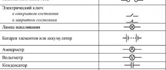
On the body of each relay there is a diagram with contact numbers and control voltage rating. A rectangle with pins 85 and 86 means a coil. Therefore, when measuring winding parameters, you need to connect to them. Other pins numbered 30, 87 and 87a (88) are the switching key for the external circuit.
It is convenient to use a digital multimeter as a tester for regulator relays and any other electromagnetic relay. This is because it can measure current, voltage and resistance.
Since the performance of the device depends primarily on the health of the winding, the test begins with measuring the coil resistance. Its values range from several tens of ohms to several hundred ohms.
To do this, switch the multimeter to resistance measurement mode. We connect measuring probes to pins 85, 86 and take readings. If the resistance is within normal limits, then you need to check the condition of the controlled outputs. In a relay with normally closed contacts 30 and 87, when measuring the resistance between them, the multimeter should show 0 Ohm. With normally open pins 30 and 87 the resistance between them should be infinity. When the control voltage is applied to the coil terminals 85 and 86, everything should change exactly the opposite.
Sometimes only the actuation current is known, then the coil resistance is measured. After this, the multimeter readings are multiplied by the operating current, and the control action of the winding is obtained. Then, by applying the calculated voltage, you can check the contact group, as described above.
Only AC voltage can be applied to the AC relay coil.
After checking the relay, if there is a need and the ability to adjust the contacts, do so. Otherwise, replace the entire device. Its installation and removal must be carried out with the device's power turned off.
Principle of operation
It all works like this: when the engine is not running, the armature of the retractor relay is pulled out of the housing due to the action of the spring on it. The same spring holds the Bendix and gear through the fork in a position where there is no engagement.
When the ignition key is turned to the start position, the solenoid relay is first activated.
The electrical energy supplied to the coils of the solenoid relay ensures the appearance of a magnetic field inside the housing.
This field acts on the armature, and it, overcoming the force of the spring, enters the body, after which the retracting coil is turned off and ceases to create a magnetic field, but in the retracted position the armature is held by the holding coil with its magnetic field.
In this case, the armature pulls the fork, which in turn moves the bendix forward along the rotor shaft, and its gear engages with the flywheel ring.
The armature, entering the housing, pushes the starter relay rod, and, moving, closes the contact plates of the positive terminals with each other.
Electricity from the battery is supplied to the brushes of the starter motor, and its rotor begins to rotate. And since the gear has already engaged, the rotor begins to rotate the flywheel.
After starting the power plant and turning the ignition key back, the power to the holding coil stops, its magnetic field disappears and the armature comes out of the housing under the influence of a spring.
At the same time, it disengages the bendix through the fork and stops acting on the relay rod. He, in turn, moving away, opens the contact plates, and the starter is completely turned off.
Application in car
Most often motorists have to deal with switching devices. We are talking about the generator (starter) regulator relay. They remember it when the engine stops starting and it turns out that the battery is discharged. One of the reasons for this is a malfunction of the regulator.
On older cars, to maintain a constant voltage, a regulator was used, consisting of three devices - a voltage stabilizer, a current limiter and a reverse current relay. The regulator prevents the battery from overcharging, which prolongs its service life. It can be built into the starter brush block or performed as a separate module. Its failure may or may not overcharge the battery. In the first case, streaks will be visible on the case, the electrolyte will begin to boil away, which will lead to a voltage drop below 12 volts. In the second, the values will initially be lower than acceptable. As a result, the engine will not start.
Malfunctions
Troubleshooting a traction relay is not that difficult. It should be noted that its operation is accompanied by a click - this is the result of the armature being retracted and the gear being engaged.
When you turn the key, this click is clearly audible. Thus, the absence of a click may indicate a break in the coils, lack of power, or the armature being stuck in one position.
If, when you turn the ignition key, a click is heard, but the starter itself does not start or starts but spins very slowly, this may indicate that the contact plates are burning.
Continued operation of the starter after starting the power plant will be accompanied by a characteristic buzzing sound.
It is possible that the armature is stuck in the retracted position and cannot return back, so it keeps the bendix gear engaged and continues to close the contact plates.
Checking the starter regulator
To check the starter regulator relay without removing it from the car, you can use a multimeter and test all the wires that go to it. To do this, they are first disconnected from the regulator. The multimeter is switched to resistance measurement mode, the disconnected wires are checked.
If everything is normal, then the conductors are returned to their place. The voltage at the battery terminals is measured with the engine off. The multimeter is switched to DC voltage measurement mode in the range from 0 to 20 Volts. The probes attach to the battery terminals. The device should show 12.2-12.7 V. If 12 volts or lower, then it needs to be recharged.
Then the engine must be started and checked again with the same measurements. If the voltage is in the range of 13.2-14 V, then this is normal. We add engine speed to 2000 per minute and measure again. Normally, the multimeter should show between 13.6-14.2 V. We also add revolutions to 3500 per minute.
Leading manufacturers
When purchasing a starter solenoid relay, it is important to pay attention not only to its characteristics and compatibility with the existing starter, but also to the manufacturer. Please note that auto parts can be offered not only by the manufacturers themselves, but also by packaging companies. Here are a few brands that car enthusiasts should know about:
The latter company is not so much a manufacturer as a packer . It is these auto parts that the driver will most likely be able to find in the store. The quality can be assessed as high, and the price as very affordable.
We wrote above that the correspondence between the relay and the starter is not always observed. Please note that popular starter manufacturers may use third-party . The most famous manufacturers of starters are the companies already mentioned above, as well as Magneton, Nikko, Mitsuba, Delco Remy, Cav, Poong Song, Delphi, Leece-Neville. Using the names of these companies, you can also start searching for the solenoid relay in the electronic catalogs of well-known online stores.
Checking the solenoid relay
When the battery is charged, but the engine does not start, you need to check the starter.
If the generator spins but the engine does not, then in such cases it is necessary to check the solenoid relay of the electric motor and the bendix. To do this, you need to remove the starter. After this, all contacts are cleaned, and the resistance of the relay winding is measured with a multimeter. If the value is infinity, then the winding has burned out. In this case, it is necessary to rewind the coil or replace it. The device shows several tens of ohms, which means the winding is intact.
Then its performance is checked. The positive terminal of the battery is connected to the corresponding relay terminal using the cigarette lighter. And the minus is connected to the starter housing. A click should be heard, then the device is working properly, otherwise it needs to be disassembled and the mechanical part checked.
Purpose of the electrical mechanism. Operating principle
- The engine control system has two power relays: the main relay and the electric fuel pump relay.
- The main relay is designed to supply onboard voltage to all actuating electric mechanisms and sensors of the system, which have a rated supply voltage of 12V.
- The electric fuel pump relay is designed to supply power to the electric fuel pump.
- Both relays are unified in design and are designed to control power circuits up to 30A. Electromagnetic type relay with normally open contacts. The relay is turned on by a signal from the control unit close to ground.
- The power circuit of the main relay coming from the battery is protected from short circuits to ground by a 20 A fuse, and the power circuit from the ignition switch is protected by a 10 A fuse (for UAZ vehicles).
Electric mechanism design
Electrical mechanism parameters
- Power supply range: 8.16V.
- Rated voltage: 12V.
- Control current: no more than 0.2A.
- Operation voltage: not less than 8.0V.
- Release voltage: 1.5. 5.0V.
- Maximum current in the power circuit: 30A.
- Active winding resistance: 80±10 Ohm.
Installation and assembly of the electrical mechanism on the car
- The main relay and the electric fuel pump relay are installed on the front panel above the engine.
- The relay is connected to the wiring harness using four-pin sockets.
- For UAZ vehicles, relay blocks are additionally equipped with blade fuses:
- 20A—on the main relay block;
- 10A—on the electric fuel pump relay block.
- The relays have no visible external differences. The main guideline can be two factors:
- larger cross-section wires are suitable for the main relay block;
- after turning on the ignition, the electric fuel pump relay turns off after about five seconds (if the starter is not turned on), and if you put your hand on the relay body, you will feel a short click when it turns off.
Analogues of electromechanism
- Automotive relay type 90.3747-10 (in a plastic case without mounting flange, 12V-30A) has analogues:
- 90.3747—in a plastic case with a mounting flange;
- 113.3747—in a metal case with a mounting flange;
- 113.3747-10—in a metal case without mounting flange;
- 111.3747—in a metal case with a mounting flange;
- 111.3747-10—in a metal case without mounting flange.
External manifestations of malfunctions in electrical mechanism circuits
Relay connection diagram for a GAZ car.
Scheme for connecting the main relay on a UAZ car.
Electric fuel pump relay connection diagram.
- The malfunction lamp does not light up after turning on the ignition. The electric fuel pump does not turn on. Self-diagnosis records fault codes 177. 179.
- Check the serviceability of the main relay circuits 58, 18, 18a, 18b, 18c, 46.
- The malfunction lamp lights up after turning on the ignition. The electric fuel pump does not turn on. Self-diagnosis records fault codes 167. 169. Check the serviceability of the circuits:
- electric fuel pump relay—18g, 37v, 3;
- electric fuel pump—57, 56.
| In this article I will give several examples of relays used in cars, their differences and some use cases. |
FAQ
Let's touch on several interesting questions that both novice drivers and very experienced car enthusiasts may ask. So:
- What is the current of the starter solenoid relay? Answer : Much depends on the model of starter and relay, but in most devices a current of 15-20 Amps passes through the control contact. In some cases this current is greater, but also remember that the strength of the current depends on whether the contacts are clean;
- How to disassemble the starter solenoid relay? Answer : This question was addressed above. In this case, you can get to the “filling” of a non-separable relay, although you cannot do without special tools and damage to the integrity of the case.
We have already described the relay repair process above. Even an inexperienced car enthusiast will not have any particular difficulties with this. The problem can only arise during the search for relay parts. However, many repair parts can be found from the already mentioned Danish company Cargo. Most of the goods offered by the company are produced in the countries of Southeast Asia, but their quality is quite high.